EP0504635B1 - Radiateur eau/air pour moteurs à combustion interne refroidis par eau - Google Patents
Radiateur eau/air pour moteurs à combustion interne refroidis par eau Download PDFInfo
- Publication number
- EP0504635B1 EP0504635B1 EP92103308A EP92103308A EP0504635B1 EP 0504635 B1 EP0504635 B1 EP 0504635B1 EP 92103308 A EP92103308 A EP 92103308A EP 92103308 A EP92103308 A EP 92103308A EP 0504635 B1 EP0504635 B1 EP 0504635B1
- Authority
- EP
- European Patent Office
- Prior art keywords
- water
- air radiator
- free end
- radiator according
- water tank
- Prior art date
- Legal status (The legal status is an assumption and is not a legal conclusion. Google has not performed a legal analysis and makes no representation as to the accuracy of the status listed.)
- Expired - Lifetime
Links
- XLYOFNOQVPJJNP-UHFFFAOYSA-N water Substances O XLYOFNOQVPJJNP-UHFFFAOYSA-N 0.000 title claims description 81
- 238000002485 combustion reaction Methods 0.000 title claims description 3
- 229920003023 plastic Polymers 0.000 claims description 11
- 239000004033 plastic Substances 0.000 claims description 11
- 239000000463 material Substances 0.000 claims description 5
- 238000002347 injection Methods 0.000 claims 1
- 239000007924 injection Substances 0.000 claims 1
- 238000000034 method Methods 0.000 description 6
- 239000003351 stiffener Substances 0.000 description 3
- 229910000831 Steel Inorganic materials 0.000 description 1
- 238000000418 atomic force spectrum Methods 0.000 description 1
- 238000010276 construction Methods 0.000 description 1
- 239000000498 cooling water Substances 0.000 description 1
- 230000000694 effects Effects 0.000 description 1
- 238000004519 manufacturing process Methods 0.000 description 1
- 239000002184 metal Substances 0.000 description 1
- 230000036316 preload Effects 0.000 description 1
- 230000003014 reinforcing effect Effects 0.000 description 1
- 239000010959 steel Substances 0.000 description 1
Images
Classifications
-
- F—MECHANICAL ENGINEERING; LIGHTING; HEATING; WEAPONS; BLASTING
- F28—HEAT EXCHANGE IN GENERAL
- F28F—DETAILS OF HEAT-EXCHANGE AND HEAT-TRANSFER APPARATUS, OF GENERAL APPLICATION
- F28F9/00—Casings; Header boxes; Auxiliary supports for elements; Auxiliary members within casings
- F28F9/001—Casings in the form of plate-like arrangements; Frames enclosing a heat exchange core
-
- F—MECHANICAL ENGINEERING; LIGHTING; HEATING; WEAPONS; BLASTING
- F28—HEAT EXCHANGE IN GENERAL
- F28F—DETAILS OF HEAT-EXCHANGE AND HEAT-TRANSFER APPARATUS, OF GENERAL APPLICATION
- F28F2275/00—Fastening; Joining
- F28F2275/08—Fastening; Joining by clamping or clipping
- F28F2275/085—Fastening; Joining by clamping or clipping with snap connection
Definitions
- the invention relates to a water / air cooler for water-cooled internal combustion engines, in particular commercial vehicles, the radiator block, including the water boxes, which are made in particular of plastic, can be fastened via side parts, which are provided at both ends with two fastening tabs laterally overlapping the water boxes , which are part of a U-shaped overlapping bow-shaped end of the side parts of the associated water box and have openings through which positively attached connecting pins on the transverse sides of the water boxes engage.
- Water / air coolers of this type are known (DE 34 28 857 A1).
- two lateral connecting pins are assigned to each side end of the water box on each side, of which the connecting pin located more towards the center of the water box is also provided with a safety device to prevent the tabs from being removed again.
- This fuse can be designed as a locking spring that is pushed onto a groove of the connecting pin.
- the connecting pin which is located more to the outside and is adjacent to the connecting pin just mentioned, is only inserted in a form-fitting manner through an associated opening and with a run-up slope provided, which is used during assembly to spread the parallel tabs laterally so far that they can be pushed over both connecting pins until they snap into the openings.
- the invention has for its object to provide a water / air cooler of the type mentioned so that the stability of the frame, i. the side part / water box connection is increased.
- a water / air cooler of the type mentioned that at least one opening is provided in the web part connecting the fastening tabs and that the water boxes are each provided on their front side with at least one of the connecting pins which form-fit which engages at least one opening in the web part.
- the maximum possible distance between the connecting pins fixedly arranged on the water tank can be realized, so that the torsional forces exerted on the frame, with the same frame dimensions, lead to smaller forces between fastening tabs and connecting pins.
- the mounting tabs also have a Form type U-bracket, which also overlaps the front of the water box with its web, an increased stability of the frame thus formed from water boxes and side parts is also achieved in this way.
- the upper edge of the fastening tabs protrude into the region of the lateral upper end of the water box, to provide guide surfaces on the water box for contact with the upper edges of the fastening tabs.
- the fastening tabs can be pre-positioned during the pushing-on process, so that the assembly process becomes easier.
- the upper edges and the guide surfaces can run perpendicular to the side surfaces of the side parts, so that a simple alignment process during assembly is also made possible in this way.
- the free end of the fastening tabs can be assigned at least one latching hook which overlaps the free end of the fastening tabs when the opening of the fastening tab engages positively around the connecting pin.
- This latching hook can be an elastically attached to the water tank pivoting part, which is preferably made of the plastic material of the water box and which according to claim 7 has at its free end a contact projection through which the latching hook from the free end still in the spread state Fastening tab is grasped and pretensioned in that it is moved from its original position to the rear.
- the mounting bracket returns to its initial position after the push-on operation, in which the two mounting brackets run parallel to one another, then the free end of the mounting brackets releases the contact projection and the latching hook can pivot back into its initial position under its pretension, in which it can then hook overlaps the outside of the fastening tab.
- the latching hook is articulated at a point on the water tank that is displaced further to the front of the water tank than the free end of the fastening tab in the pushed-on state of the fastening on the water tank.
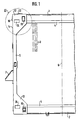
- a water / air cooler for a commercial vehicle which consists of an upper, made of plastic water box (1) and also made of plastic lower water box (2), between which in a known manner pipes for Guide the cooling water are arranged, of which only the axes (3) are shown.
- the pipe axes (3) run perpendicular to the mounting flanges (4) of the water boxes (1 and 2).
- These tubes are provided with fins in a known manner and, together with the tube sheets (not shown), form a finned tube block which is produced by a soldered connection.
- the tube sheets are crimped to the associated flange (4) of the water boxes (1 or 2), as is also known.
- side parts (5) are provided, of which only the left side part (5) is shown in FIG. 1, which shows only about half of the entire water / air cooler .
- these side parts (5) are made of steel, but they can also consist of another metal or of a plastic with sufficient stability, in particular of a plastic which is provided in a known manner with reinforcing inserts.
- Both side parts (5) are arranged symmetrically to the central axis (6) of the cooler and, as indicated in FIG. 1, are provided with fastening devices, as indicated for example at (7).
- the fastening device (7) consists of a fastening bracket which forms a support surface which can then be supported on part of the frame structure of the commercial vehicle, not shown.
- the side part (5) - as well as the symmetrical side part on the other side - is provided at the upper and lower end with fastening tabs (12 and 13) which laterally overlap the upper water tank (1) and the lower water tank (2).
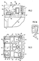
- the fastening tabs (12 and 13) each consist of two tab parts (12, 12a - and 13, 13a) which overlap the water boxes (1 and 2) on their front and rear sides, which can also be seen in FIG. 3.
- These fastening tabs (12, 12a) are part of a bow-shaped end (5a) which surrounds the end face of the water tank (1) in a U-shape, the web part (14) connecting the two tabs (12, 12a) to the upper edge (15) of the fastening tabs ( 12, 12a) completes.
- At least one opening is provided in the web part (14); in the exemplary embodiment, two openings (16, 16a) are provided which run symmetrically to the longitudinal center plane (17) of the water tank (1) and are dimensioned such that cam-like connecting pins (18) which are provided on the face of the water box (1) projecting outwards, reach into these openings (16, 16a) in a form-fitting manner. As can be seen in FIGS. 2 and 3, the free end of these connecting pins (18) only protrude slightly beyond the outer contour of the web part (14).
- connecting pins (19) are provided in the area of the tabs (12, 12a - 13 and 13a) on the front and rear, which in the exemplary embodiment have an approximately rectangular, Have cross-section similar to a pipe socket and, in the assembled state of the side parts (5) shown in FIGS. 2 and 3, positively engage in openings (20), likewise of rectangular cross-section.
- the connecting pins (19) are, like the connecting pins (18), attached in one piece to the water tank (1) made of plastic, which, as shown in FIG. 3, for manufacturing and stability reasons with rib-like stiffeners (21) on its top is provided. As is known per se, these stiffeners extend into the areas in which the connecting pins (18 and 19) are arranged.
- the fixed-case-side water tank (1) also has strips (22) which are fixed to it and laterally protrude from the upper side and which have guide surfaces (23) for the upper edge (15) of the fixing tabs (12) on their underside facing the fixing tabs (12 - or 13) - or 13) form.
- the fastening tabs (12 and 13) are provided in the area between their openings (20) and the web part (14) with rectangular windows (24) which, in the assembled state of the side parts, attached firmly to the sides of the water boxes (1 and 2) There are cams (25) which are provided with a run-up slope (26) on the side facing the front of the water tank (1 or 2).
- the dimensions of the ramp (26) and the cams (25) are chosen so that the free ends (12 'and 12a') of the fastening tabs (12 and 12a) - analogously (13 and 13a) - during assembly on the Water boxes (1 or 2) and in the case of the side sliding open for this purpose are spread apart, so far that during the side sliding on operation they are led with their free ends over the free ends of the connecting pins (19) can be.
- the upper edges (15) of the fastening tabs (12) can be placed on the guide surfaces (23) of the strips (22).
- the window (24) in the fastening tabs is designed so that it comes to rest in front of the cams (25) as soon as the free ends (12 ') are in the area of the fastening pins (19), so that the fastening tabs are on them Can connect connecting pins.
- each water tank (1 or 2) there are finally provided locking hooks (30) assigned to the two sides which, as shown in FIG. 3, with their hook-like end (30 ') the free end (12' or 12a ') of overlap assigned fastening tab in the assembled state.
- the locking hooks (30) are articulated at a point (27) on the water tank (1) or on one of its stiffeners, which is displaced further to the front side of the water tank (1 or 2) than the free end (12 'or 12a ') of the fastening tab (12 or 12a) in the fastened and pushed-on state, as can be clearly seen from FIG. 3.
- Each locking hook (30) also has at its free end a contact projection (28), the function of which will be discussed in the description of the assembly process.
- Fig. 3a shows that due to the arrangement of the articulation point (27), the elastic locking hooks (30), which of course preferably consist of the same plastic material as the water tank (1) and are molded directly, when a force (31) exerted on them, which tries to detach the fastening tabs (12, 12a) from the connecting pins (19), are also subjected to a force component (29) which presses the hook end of the latching hooks (30) towards the free end of the fastening tabs.
- a force component (29) which presses the hook end of the latching hooks (30) towards the free end of the fastening tabs.
- the selected configuration makes it easy to proceed in such a way that the side parts each with the outer edges (15) of their fastening tabs (12 or 12a) first from the outside on the guide surfaces (23) be created.
- the side parts (5) are then pushed onto the water boxes (1 or 2) with their fastening tabs (12, 13) perpendicular to the central longitudinal plane (6) of the finned tube block.
- the fastening tabs (12, 12a or 13, 13a) spread out through the run-up of their ends on the run-up bevels (26) and are held in this spread position when the free ends (12 ') are on the outer end faces of the connecting pins ( 19) hang up while the window (24) slides over the cams (25) and the run-up slopes (26).
- the free ends (12 ') abut the contact projections (28) of the latching hooks and press them towards the center of the water boxes into a prestressed position.
- the fastening tabs (12, 12a - or 13, 13a) snap onto the connecting pins (19) under their own tension, while the connecting pins (18) simultaneously reach their end position in the openings (16 ) in the web part (14).
- the free ends (12 ', 12a') of the fastening tabs release the contact projections (28) and the free end parts (30 ') of the latching hooks (30), so that they move into the securing position shown in FIG. 3 due to their Can swivel the preload back and attach to the mounting brackets from the outside.
- the assembly position is thus secured. As previously explained, this cannot be solved even when forces are exerted on the fastening tabs.
- the latching hooks (30) must first be pushed away from the end of the fastening straps, after which the fastening straps must be spread out before they are pulled off the water boxes again.
- the disassembly is therefore much more complex than the assembly, which, as explained, can be done by simply sliding it on without any tools.
Landscapes
- Engineering & Computer Science (AREA)
- Physics & Mathematics (AREA)
- Thermal Sciences (AREA)
- Mechanical Engineering (AREA)
- General Engineering & Computer Science (AREA)
- Air-Conditioning For Vehicles (AREA)
- Cooling, Air Intake And Gas Exhaust, And Fuel Tank Arrangements In Propulsion Units (AREA)
Claims (9)
- Radiateur eau/air pour moteurs à combustion interne refroidis à l'eau, en particulier de véhicules utilitaires, dont le bloc de radiateur, y compris les boites à eau en particulier en matière plastique, se fixe au moyen de pièces latérales (5) qui comportent à chacune des deux extrémités deux pattes de fixation (12, 12a, 13) qui se placent latéralement sur les boites à eau (1, 2) et qui font partie d'une extrémité en étrier (5a) des pièces latérales (5) en forme de U qui passe autour du côté extrême de la boite à eau correspondante (1 ainsi que 2), ces pattes de fixation comportant des trous (20) dans lesquels pénètrent des tenons de liaison (19) de forme complémentaire qui sont solidarisés avec les côtés transversaux des boites à eau, caractérisé en ce qu'au moins un trou (16) est prévu dans l'âme (14) qui relie les pattes de fixation et en ce que les boites à eau (1, 2) comportent sur chacun de leurs côtés extrêmes au moins un tenon de liaison (18) qui pénètre par complémentarité de formes dans le au moins un trou (16) de l'âme (14).
- Radiateur eau/air selon la revendication 1, caractérisé en ce qu'au moins une surface de guidage (23) d'appui contre le bord supérieur (15) des pattes de fixation (12 ainsi que 12a) est prévue sur la boite à eau (1).
- Radiateur eau/air selon la revendication 1, caractérisé en ce qu'au moins un plan incliné en rampe (26) d'écartement des pattes de fixation (12, 12, 13) s'emboitant latéralement est réalisé latéralement sur les boites à eau (1, 2) et dans la région comprise entre les tenons latéraux de liaison (19) et le côté extrême.
- Radiateur eau/air selon la revendication 3, caractérisé en ce que chaque patte de fixation (12, 12a) comporte une fenêtre (24) qui se place à l'alignement du plan incliné en rampe (26) lorsque, au cours de l'emboîtement latéral des pattes de fixation, l'extrémité libre (12', 12a') de ces dernières est placée sur l'extrémité libre du tenon latéral de liaison (19).
- Radiateur eau/air selon l'une des revendications 1 à 4, caractérisé en ce qu'au moins un crochet d'arrêt (30) passant de l'extérieur par dessus l'extrémité libre de la patte de fixation, lorsque le trou (20) de la patte de fixation entoure par complémentarité de formes le tenon latéral de liaison (19), est affecté à l'extrémité libre (12', 12a') de chacune des pattes de fixation (12, 12a).
- Radiateur eau/air selon la revendication 5, caractérisé en ce que le crochet d'arrêt (30) est conformé en pièce fléchissant élastiquement et réalisée sur la boite à eau (1, 2).
- Radiateur eau/air selon la revendication 6, caractérisé en ce que la pièce fléchissante comporte à l'extrémité libre une saillie d'appui (28) par laquelle le crochet d'arrêt (30) peut être mis sous précontrainte par l'extrémité libre encore écartée de la patte de fixation (12, 12a).
- Radiateur eau/air selon la revendication 6 ou 7, caractérisé en ce que le crochet d'arrêt (30) est articulé en un emplacement (27) de la boite à eau (1 ainsi que 2) qui est plus proche du côté extrême de la boîte à eau que l'extrémité libre (12', 12a') de la patte de fixation (12, 12a) occupant l'état d'emboîtement et de montage.
- Radiateur eau/air selon l'une des revendications 6 à 8, caractérisé en ce que le crochet d'arrêt (30) est venu en une pièce de moulage par injection avec la boîte à eau (1 ainsi que 2) réalisée en matière plastique.
Applications Claiming Priority (2)
| Application Number | Priority Date | Filing Date | Title |
|---|---|---|---|
| DE4109284 | 1991-03-21 | ||
| DE4109284A DE4109284A1 (de) | 1991-03-21 | 1991-03-21 | Wasser/luft-kuehler fuer wassergekuehlte verbrennungskraftmaschinen |
Publications (2)
| Publication Number | Publication Date |
|---|---|
| EP0504635A1 EP0504635A1 (fr) | 1992-09-23 |
| EP0504635B1 true EP0504635B1 (fr) | 1994-02-02 |
Family
ID=6427888
Family Applications (1)
| Application Number | Title | Priority Date | Filing Date |
|---|---|---|---|
| EP92103308A Expired - Lifetime EP0504635B1 (fr) | 1991-03-21 | 1992-02-27 | Radiateur eau/air pour moteurs à combustion interne refroidis par eau |
Country Status (3)
| Country | Link |
|---|---|
| EP (1) | EP0504635B1 (fr) |
| DE (2) | DE4109284A1 (fr) |
| ES (1) | ES2048602T3 (fr) |
Cited By (2)
| Publication number | Priority date | Publication date | Assignee | Title |
|---|---|---|---|---|
| CN103327797A (zh) * | 2013-07-05 | 2013-09-25 | 河南省法斯特散热器有限公司 | 一种卧式水箱散热器 |
| CN103327796A (zh) * | 2013-07-05 | 2013-09-25 | 河南省法斯特散热器有限公司 | 一种流动供电设备上配套安装的水散热器 |
Families Citing this family (11)
| Publication number | Priority date | Publication date | Assignee | Title |
|---|---|---|---|---|
| FR2697907B1 (fr) * | 1992-11-09 | 1995-01-20 | Valeo Thermique Moteur Sa | Echangeur de chaleur à boîtes à eau reliées par des montants, notamment pour véhicule automobile. |
| DE4243204C2 (de) * | 1992-12-19 | 1995-10-26 | Behr Gmbh & Co | Wasser-Luft-Kühler für wassergekühlte Verbrennungskraftmaschinen |
| FR2706994A1 (en) * | 1993-06-24 | 1994-12-30 | Valeo Thermique Moteur Sa | Heat exchanger with water (header) boxes connected by uprights |
| DE4332919B4 (de) * | 1993-09-28 | 2007-02-22 | Valeo Gmbh | Wasserkühler mit Ladeluftkühler |
| US5875907A (en) * | 1997-06-17 | 1999-03-02 | Aptargroup, Inc. | Tamper-evident dispensing closure for a container |
| DE29712351U1 (de) * | 1997-07-12 | 1997-09-11 | Behr GmbH & Co., 70469 Stuttgart | Wärmeübertrageranordnung mit zwei Wärmeübertragern |
| DE19824700A1 (de) * | 1998-06-03 | 1999-12-09 | Behr Gmbh & Co | Wärmeübertrager, insbesondere Kühler für Kraftfahrzeuge |
| DE19844048B4 (de) * | 1998-09-25 | 2012-02-02 | Behr Gmbh & Co. Kg | Wärmeübertrager, insbesondere für Kraftfahrzeuge |
| DE29822378U1 (de) | 1998-12-16 | 1999-02-25 | Längerer & Reich GmbH, 70794 Filderstadt | Wasser/Luft-Kühler |
| FR2793012B1 (fr) * | 1999-04-29 | 2001-07-27 | Valeo Thermique Moteur Sa | Echangeur de chaleur ayant des tubes souples, en particulier pour vehicule automobile |
| US6513579B1 (en) * | 2001-09-27 | 2003-02-04 | Delphi Technologies, Inc. | Post braze heat exchanger mounting and support brackets |
Family Cites Families (6)
| Publication number | Priority date | Publication date | Assignee | Title |
|---|---|---|---|---|
| US4230176A (en) * | 1978-04-24 | 1980-10-28 | Caterpillar Tractor Co. | Floating radiator tank top |
| US4382464A (en) * | 1981-08-12 | 1983-05-10 | Ex-Cell-O Corporation | Radiator |
| DE3303986A1 (de) * | 1983-02-05 | 1984-08-09 | Süddeutsche Kühlerfabrik Julius Fr. Behr GmbH & Co KG, 7000 Stuttgart | Wasser/luft-kuehler fuer wassergekuehlte verbrennungskraftmaschinen, insbesondere von nutzfahrzeugen |
| DE3428857A1 (de) * | 1984-08-04 | 1986-02-13 | Süddeutsche Kühlerfabrik Julius Fr. Behr GmbH & Co KG, 7000 Stuttgart | Wasser/luft-kuehler fuer wassergekuehlte verbrennungskraftmaschinen |
| DE3536457A1 (de) * | 1985-10-12 | 1987-06-25 | Sueddeutsche Kuehler Behr | Waermetauscher, insbesondere kuehler fuer kraftfahrzeuge |
| DE3820623A1 (de) * | 1988-06-17 | 1989-12-21 | Sueddeutsche Kuehler Behr | Wasser/luft-kuehler fuer wassergekuehlte verbrennungskraftmaschinen, insbesondere von nutzfahrzeugen |
-
1991
- 1991-03-21 DE DE4109284A patent/DE4109284A1/de not_active Withdrawn
-
1992
- 1992-02-27 DE DE92103308T patent/DE59200060D1/de not_active Expired - Lifetime
- 1992-02-27 EP EP92103308A patent/EP0504635B1/fr not_active Expired - Lifetime
- 1992-02-27 ES ES92103308T patent/ES2048602T3/es not_active Expired - Lifetime
Cited By (4)
| Publication number | Priority date | Publication date | Assignee | Title |
|---|---|---|---|---|
| CN103327797A (zh) * | 2013-07-05 | 2013-09-25 | 河南省法斯特散热器有限公司 | 一种卧式水箱散热器 |
| CN103327796A (zh) * | 2013-07-05 | 2013-09-25 | 河南省法斯特散热器有限公司 | 一种流动供电设备上配套安装的水散热器 |
| CN103327796B (zh) * | 2013-07-05 | 2015-09-02 | 河南省法斯特散热器有限公司 | 一种流动供电设备上配套安装的水散热器 |
| CN103327797B (zh) * | 2013-07-05 | 2016-03-30 | 河南省法斯特散热器有限公司 | 一种卧式水箱散热器 |
Also Published As
| Publication number | Publication date |
|---|---|
| DE59200060D1 (de) | 1994-03-17 |
| ES2048602T3 (es) | 1994-03-16 |
| EP0504635A1 (fr) | 1992-09-23 |
| DE4109284A1 (de) | 1992-09-24 |
Similar Documents
| Publication | Publication Date | Title |
|---|---|---|
| EP0170952B1 (fr) | Radiateur eau/air pour moteur à combustion refroidi à l'eau | |
| EP0401571B1 (fr) | Echangeur de chaleur pour refroidir l'eau de refroidissement et l'air comprimé d'un moteur à combustion interne | |
| EP0504635B1 (fr) | Radiateur eau/air pour moteurs à combustion interne refroidis par eau | |
| DE2449045C3 (de) | Anordnung zur Verbindung der Rohrplatten, der Seitenteile und des Wasserkastens eines Wärmetauschers | |
| EP3488498B1 (fr) | Ensemble formant cadre de support muni d'un cadre de base et d'un élément de fixation et procédé d'assemblage | |
| DE19953787B4 (de) | Anordnung zur Verbindung von zwei Wärmeübertragern | |
| EP0219021A2 (fr) | Echangeur de chaleur, en particulier refroidisseur pour véhicules automobiles | |
| DE4244037C2 (de) | Kühlaggregat für einen Verbrennungsmotor | |
| DE102017108432A1 (de) | Halterahmen für einen Steckverbinder und Verfahren zur Bestückung | |
| DE29707571U1 (de) | Anordnung zur Verbindung von zwei Wärmetauschern | |
| EP3452667B1 (fr) | Caniveau de drainage superficiel avec une paroi frontale | |
| DE3744644A1 (de) | Vorrichtung zum befestigen einer luefterhaube am wasserkasten eines luft/wasser-kuehlers fuer kraftfahrzeuge | |
| DE4244039C2 (de) | Kühlmodul für Verbrennungskraftmaschinen | |
| EP1439364A1 (fr) | Support pour échangeur de chaleur | |
| EP0299187B1 (fr) | Chaise porteuse en matière plastique pour lignes de transport d'énergie | |
| EP0280107A1 (fr) | Refroidisseur eau-air | |
| DE3907926A1 (de) | Waermetauscher, insbesondere kuehler fuer nutzfahrzeuge | |
| DE1939135C3 (de) | Wasserkühler für Kraftfahrzeuge, Erdbewegungsmaschinen u.dgl | |
| EP0401590B1 (fr) | Echangeur de chaleur | |
| EP0932010B1 (fr) | Echangeur de chaleur | |
| DE19953786B4 (de) | Kühlmittelkühler mit einem Ausgleichsbehälter | |
| DE4041671A1 (de) | Waermetauscher | |
| DE3222301A1 (de) | Wasserkuehler, vorzugsweise fuer eine brennkraftmaschine | |
| DE3527054A1 (de) | Waermetauscher, insbesondere wasser/luftkuehler fuer verbrennungskraftmaschinen | |
| EP1225092B1 (fr) | Miroir d'automobile |
Legal Events
| Date | Code | Title | Description |
|---|---|---|---|
| PUAI | Public reference made under article 153(3) epc to a published international application that has entered the european phase |
Free format text: ORIGINAL CODE: 0009012 |
|
| AK | Designated contracting states |
Kind code of ref document: A1 Designated state(s): DE ES FR GB IT SE |
|
| 17P | Request for examination filed |
Effective date: 19921016 |
|
| 17Q | First examination report despatched |
Effective date: 19930204 |
|
| GRAA | (expected) grant |
Free format text: ORIGINAL CODE: 0009210 |
|
| AK | Designated contracting states |
Kind code of ref document: B1 Designated state(s): DE ES FR GB IT SE |
|
| ITF | It: translation for a ep patent filed | ||
| REG | Reference to a national code |
Ref country code: ES Ref legal event code: FG2A Ref document number: 2048602 Country of ref document: ES Kind code of ref document: T3 |
|
| REF | Corresponds to: |
Ref document number: 59200060 Country of ref document: DE Date of ref document: 19940317 |
|
| GBT | Gb: translation of ep patent filed (gb section 77(6)(a)/1977) |
Effective date: 19940323 |
|
| ET | Fr: translation filed | ||
| PLBE | No opposition filed within time limit |
Free format text: ORIGINAL CODE: 0009261 |
|
| STAA | Information on the status of an ep patent application or granted ep patent |
Free format text: STATUS: NO OPPOSITION FILED WITHIN TIME LIMIT |
|
| 26N | No opposition filed | ||
| EAL | Se: european patent in force in sweden |
Ref document number: 92103308.0 |
|
| PGFP | Annual fee paid to national office [announced via postgrant information from national office to epo] |
Ref country code: GB Payment date: 19980121 Year of fee payment: 7 |
|
| PGFP | Annual fee paid to national office [announced via postgrant information from national office to epo] |
Ref country code: ES Payment date: 19980219 Year of fee payment: 7 |
|
| PG25 | Lapsed in a contracting state [announced via postgrant information from national office to epo] |
Ref country code: GB Free format text: LAPSE BECAUSE OF NON-PAYMENT OF DUE FEES Effective date: 19990227 |
|
| PG25 | Lapsed in a contracting state [announced via postgrant information from national office to epo] |
Ref country code: ES Free format text: LAPSE BECAUSE OF EXPIRATION OF PROTECTION Effective date: 19990301 |
|
| GBPC | Gb: european patent ceased through non-payment of renewal fee |
Effective date: 19990227 |
|
| REG | Reference to a national code |
Ref country code: ES Ref legal event code: FD2A Effective date: 20010601 |
|
| PG25 | Lapsed in a contracting state [announced via postgrant information from national office to epo] |
Ref country code: IT Free format text: LAPSE BECAUSE OF NON-PAYMENT OF DUE FEES Effective date: 20050227 |
|
| PGFP | Annual fee paid to national office [announced via postgrant information from national office to epo] |
Ref country code: SE Payment date: 20080219 Year of fee payment: 17 |
|
| PGFP | Annual fee paid to national office [announced via postgrant information from national office to epo] |
Ref country code: FR Payment date: 20080215 Year of fee payment: 17 |
|
| EUG | Se: european patent has lapsed | ||
| REG | Reference to a national code |
Ref country code: FR Ref legal event code: ST Effective date: 20091030 |
|
| PG25 | Lapsed in a contracting state [announced via postgrant information from national office to epo] |
Ref country code: FR Free format text: LAPSE BECAUSE OF NON-PAYMENT OF DUE FEES Effective date: 20090302 |
|
| PGFP | Annual fee paid to national office [announced via postgrant information from national office to epo] |
Ref country code: DE Payment date: 20100308 Year of fee payment: 19 |
|
| PG25 | Lapsed in a contracting state [announced via postgrant information from national office to epo] |
Ref country code: SE Free format text: LAPSE BECAUSE OF NON-PAYMENT OF DUE FEES Effective date: 20090228 |
|
| REG | Reference to a national code |
Ref country code: DE Ref legal event code: R119 Ref document number: 59200060 Country of ref document: DE Effective date: 20110901 |
|
| PG25 | Lapsed in a contracting state [announced via postgrant information from national office to epo] |
Ref country code: DE Free format text: LAPSE BECAUSE OF NON-PAYMENT OF DUE FEES Effective date: 20110901 |