EP0504635A1 - Radiateur eau/air pour moteurs à combustion interne refroidis par eau - Google Patents
Radiateur eau/air pour moteurs à combustion interne refroidis par eau Download PDFInfo
- Publication number
- EP0504635A1 EP0504635A1 EP92103308A EP92103308A EP0504635A1 EP 0504635 A1 EP0504635 A1 EP 0504635A1 EP 92103308 A EP92103308 A EP 92103308A EP 92103308 A EP92103308 A EP 92103308A EP 0504635 A1 EP0504635 A1 EP 0504635A1
- Authority
- EP
- European Patent Office
- Prior art keywords
- water
- air cooler
- fastening
- fastening tabs
- cooler according
- Prior art date
- Legal status (The legal status is an assumption and is not a legal conclusion. Google has not performed a legal analysis and makes no representation as to the accuracy of the status listed.)
- Granted
Links
- XLYOFNOQVPJJNP-UHFFFAOYSA-N water Substances O XLYOFNOQVPJJNP-UHFFFAOYSA-N 0.000 title claims abstract description 82
- 238000002485 combustion reaction Methods 0.000 title claims description 3
- 238000000034 method Methods 0.000 description 8
- 239000000463 material Substances 0.000 description 3
- 239000003351 stiffener Substances 0.000 description 3
- 238000010276 construction Methods 0.000 description 2
- 229910000831 Steel Inorganic materials 0.000 description 1
- 238000000418 atomic force spectrum Methods 0.000 description 1
- 239000000498 cooling water Substances 0.000 description 1
- 230000000694 effects Effects 0.000 description 1
- 238000004519 manufacturing process Methods 0.000 description 1
- 239000002184 metal Substances 0.000 description 1
- 230000036316 preload Effects 0.000 description 1
- 230000003014 reinforcing effect Effects 0.000 description 1
- 239000010959 steel Substances 0.000 description 1
Images

Classifications
-
- F—MECHANICAL ENGINEERING; LIGHTING; HEATING; WEAPONS; BLASTING
- F28—HEAT EXCHANGE IN GENERAL
- F28F—DETAILS OF HEAT-EXCHANGE AND HEAT-TRANSFER APPARATUS, OF GENERAL APPLICATION
- F28F9/00—Casings; Header boxes; Auxiliary supports for elements; Auxiliary members within casings
- F28F9/001—Casings in the form of plate-like arrangements; Frames enclosing a heat exchange core
-
- F—MECHANICAL ENGINEERING; LIGHTING; HEATING; WEAPONS; BLASTING
- F28—HEAT EXCHANGE IN GENERAL
- F28F—DETAILS OF HEAT-EXCHANGE AND HEAT-TRANSFER APPARATUS, OF GENERAL APPLICATION
- F28F2275/00—Fastening; Joining
- F28F2275/08—Fastening; Joining by clamping or clipping
- F28F2275/085—Fastening; Joining by clamping or clipping with snap connection
Definitions
- the invention relates to a water / air cooler for water-cooled internal combustion engines, in particular commercial vehicles, the radiator block, including the water boxes, which are made in particular of plastic, can be fastened via side parts, which are provided at both ends with two fastening tabs laterally overlapping the water boxes which have openings through which connecting pins firmly attached to the water boxes engage.
- Water / air coolers of this type are known (DE 34 28 857 A1).
- two lateral connecting pins are assigned to each side end of the water box on each side, of which the connecting pin located more towards the center of the water box is also provided with a safety device to prevent the tabs from being removed again.
- This fuse can be designed as a locking spring that is pushed onto a groove of the connecting pin.
- connection pin which is just adjacent to the connection pin just mentioned, is only positively inserted through an associated opening and with a run-up slope provided that serves during assembly to spread the parallel tabs laterally so far that they can be pushed over both connecting pins until they snap into the openings.
- the invention has for its object to provide a water / air cooler of the type mentioned so that the stability of the frame, i. the side part / water box connection is increased.
- the fastening tabs are part of a U-shaped cross-shaped end of the side parts of the front end of the water box, that at least one opening is provided in the web part connecting the fastening tabs and that the water boxes are each provided on their front side and on both transverse sides with at least one of the connecting pins, each connecting pin engaging in a form-fitting manner on the front side through the at least one opening in the web part.
- the maximum possible distance between the connecting pins fixedly arranged on the water box can be realized, so that the torsional forces exerted on the frame, with the same frame dimensions, lead to smaller forces between fastening tabs and connecting pins.
- the mounting tabs also have a Form type U-bracket, which also overlaps the end face of the water box with its web, an increased stability of the frame thus formed from water boxes and side parts is also achieved in this way.
- the upper edge of the fastening tabs protrude into the area of the lateral upper end of the water box, to provide guide surfaces on the water box for contact with the upper edges of the fastening tabs.
- the fastening tabs can be pre-positioned during the pushing-on process, so that the assembly process becomes easier.
- the upper edges and the guide surfaces can run perpendicular to the side surfaces of the side parts, so that a simple alignment process during assembly is also made possible in this way.
- the free end of the fastening tabs can be assigned at least one latching hook which overlaps the free end of the fastening tabs when the opening of the fastening tab engages positively around the connecting pin.
- This latching hook can be an elastically attached to the water box swivel part, which is preferably made of the plastic material of the water box and which according to claim 7 has at its free end a contact projection through which the latching hook from the free end still in the spread state Fastening tab is grasped and pretensioned in that it is moved from its original position to the rear.
- the mounting bracket returns to its starting position after the slide-on process, in which the two mounting brackets run parallel to one another, then the free end of the mounting brackets releases the contact projection and the latching hook can pivot back into its starting position under its pretension, in which it then hooks overlaps the outside of the fastening tab.
- the locking hook is articulated at a point on the water tank that is shifted further to the front of the water tank than the free end of the fastening tab in the pushed-on state of the fastening to the water tank.
- This measure namely, when forces are exerted on the latching hook from the fastening tab, which could cause a spreading and thus a possible loosening of the fastening tabs, also causes a force component that presses the latching hook towards the fastening tab, so that an unintentional There is no need to fear that the latching hook, which serves as a safeguard.
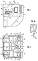
- a water / air cooler for a commercial vehicle which consists of an upper, made of plastic water tank (1) and also made of plastic lower water tank (2), between which pipes for Guide the cooling water are arranged, of which only the axes (3) are shown.
- the pipe axes (3) run perpendicular to the mounting flanges (4) of the water boxes (1 and 2).
- These tubes are provided with fins in a known manner and, together with the tube sheets (not shown), form a finned tube block which is produced by a soldered connection.
- the tube sheets are crimped to the associated flange (4) of the water boxes (1 or 2), as is also known.
- side parts (5) are provided, of which only the left side part (5) is shown in FIG. 1, which shows only about half of the entire water / air cooler .
- these side parts (5) are made of steel, but they can also consist of another metal or of a plastic with sufficient stability, in particular of a plastic which is provided with reinforcing inserts in a known manner.
- Both side parts (5) are arranged symmetrically to the central axis (6) of the cooler and, as indicated in FIG. 1, are provided with fastening devices, as indicated for example at (7).
- the fastening device (7) consists of a fastening bracket which forms a support surface which can then be supported on part of the frame construction of the commercial vehicle, not shown.
- the side part (5) - as well as the symmetrical side part on the other side - is provided at the upper and lower end with fastening tabs (12 and 13) which laterally overlap the upper water tank (1) and the lower water tank (2).
- the fastening tabs (12 and 13) each consist of two tab parts (12, 12a - and 13, 13a) which overlap the water boxes (1 and 2) on their front and rear sides, which can also be seen in FIG. 3.
- These fastening tabs (12, 12a) are part of a bow-shaped end (5a) which surrounds the end face of the water tank (1) in a U-shape, the web part (14) connecting the two tabs (12, 12a) to the upper edge (15) of the fastening tabs (12, 12a) completes.
- At least one opening is provided in the web part (14), in the exemplary embodiment two openings (16, 16a) are provided which run symmetrically to the longitudinal center plane (17) of the water tank (1) and are dimensioned such that cam-like connecting pins (18) which are provided on the end of the water box (1) projecting outwards, engage in these openings (16, 16a) in a form-fitting manner.
- cam-like connecting pins (18) which are provided on the end of the water box (1) projecting outwards, engage in these openings (16, 16a) in a form-fitting manner.
- these connecting pins (18) protrude with their free end only slightly beyond the outer contour of the web part (14).
- connecting pins (19) on the front and back which in the exemplary embodiment have an approximately rectangular, Have cross-section similar to a pipe socket and, in the assembled state of the side parts (5) shown in FIGS. 2 and 3, engage positively in openings (20), likewise of rectangular cross-section.
- the connecting pins (19), like the connecting pins (18), are attached in one piece to the water box (1) made of plastic, which, as shown in FIG. 3, for manufacturing and stability reasons with rib-like stiffeners (21) on its top is provided. As is known per se, these stiffeners are guided into the areas in which the connecting pins (18 or 19) are arranged.
- the fixed-side water tank (1) also has strips (22) which are fixed to it and which project laterally from the upper side and which have guide surfaces (23) for the upper edge (15) of the fixing tabs (12) on their underside facing the fixing tabs (12 - or 13) - or 13) form.
- the fastening tabs (12 and 13) are provided in the area between their openings (20) and the web part (14) with rectangular windows (24) which, in the assembled state of the side parts, firmly attached to the sides of the water boxes (1 and 2) There are cams (25) which are provided with a run-up slope (26) on the side facing the front of the water tank (1 or 2).
- the dimensions of the ramp (26) and the cams (25) are chosen so that the free ends (12 'and 12a') of the fastening tabs (12 and 12a) - analogously (13 and 13a) - during assembly on the Water boxes (1 or 2) and in the case of the side sliding open for this purpose are spread apart, so far that during the side sliding open-end process they run with their free ends over the free ends of the connecting pins (19) can be.
- the upper edges (15) of the fastening tabs (12) can be placed on the guide surfaces (23) of the strips (22).
- the window (24) in the fastening tabs is designed so that it comes to rest in front of the cams (25) as soon as the free ends (12 ') are in the area of the fastening pins (19), so that the fastening tabs are on them Can connect connecting pins.
- each water tank (1 or 2) there are finally provided locking hooks (30) assigned to the two sides which, as shown in FIG. 3, with their hook-like end (30 ') the free end (12' or 12a ') of overlap assigned fastening tab in the assembled state.
- the latching hooks (30) are articulated at a point (27) on the water tank (1) or on one of its stiffeners, which is displaced further to the front side of the water tank (1 or 2) than the free end (12 'or 12a ') of the fastening tab (12 or 12a) in the fastened and pushed-on state, as can be clearly seen from FIG. 3.
- Each locking hook (30) also has at its free end a contact projection (28), the function of which will be discussed in the description of the assembly process.
- Fig. 3a shows that due to the arrangement of the articulation point (27), the elastic locking hooks (30), which preferably of course consist of the same plastic material as the water tank (1) and are molded directly, when a force (31) exerted on them, which tries to detach the fastening tabs (12, 12a) from the connecting pins (19), are also subjected to a force component (29) which presses the hook end of the latching hooks (30) towards the free end of the fastening tabs.
- a force component (29) which presses the hook end of the latching hooks (30) towards the free end of the fastening tabs.
- the selected configuration makes it easy to proceed so that the side parts each with the outer edges (15) of their fastening tabs (12 or 12a) first from the outside on the guide surfaces (23) be created.
- the side parts (5) are then pushed onto the water boxes (1 or 2) with their fastening tabs (12, 13) perpendicular to the central longitudinal plane (6) of the finned tube block.
- the fastening tabs (12, 12a or 13, 13a) spread out through the run-up of their ends on the run-up bevels (26) and are held in this spread position when the free ends (12 ') are on the outer end faces of the connecting pins ( 19) hang up while the window (24) slides over the cams (25) and the run-up slopes (26).
- the free ends (12 ') abut the contact projections (28) of the latching hooks and press them towards the center of the water boxes into a prestressed position.
- the fastening lugs (12, 12a - or 13, 13a) snap onto the connecting pins (19) under their own tension, while the connecting pins (18) simultaneously reach their end position in the openings (16 ) in the web part (14).
- the free ends (12 ', 12a') of the fastening tabs release the contact projections (28) and the free end parts (30 ') of the latching hooks (30), so that they move into the securing position shown in FIG. 3 due to their Can swivel the preload back and attach to the mounting brackets from the outside.
- the assembly position is thus secured. As previously explained, this cannot be solved even when forces are exerted on the fastening tabs.
- the latching hooks (30) must first be pushed away from the end of the fastening straps, after which the fastening straps must be spread out before they are pulled off the water boxes again.
- the disassembly is therefore much more complex than the assembly, which, as explained, can be done by simply sliding it on without any tools.
Landscapes
- Engineering & Computer Science (AREA)
- Physics & Mathematics (AREA)
- Thermal Sciences (AREA)
- Mechanical Engineering (AREA)
- General Engineering & Computer Science (AREA)
- Air-Conditioning For Vehicles (AREA)
- Cooling, Air Intake And Gas Exhaust, And Fuel Tank Arrangements In Propulsion Units (AREA)
Applications Claiming Priority (2)
| Application Number | Priority Date | Filing Date | Title |
|---|---|---|---|
| DE4109284 | 1991-03-21 | ||
| DE4109284A DE4109284A1 (de) | 1991-03-21 | 1991-03-21 | Wasser/luft-kuehler fuer wassergekuehlte verbrennungskraftmaschinen |
Publications (2)
| Publication Number | Publication Date |
|---|---|
| EP0504635A1 true EP0504635A1 (fr) | 1992-09-23 |
| EP0504635B1 EP0504635B1 (fr) | 1994-02-02 |
Family
ID=6427888
Family Applications (1)
| Application Number | Title | Priority Date | Filing Date |
|---|---|---|---|
| EP92103308A Expired - Lifetime EP0504635B1 (fr) | 1991-03-21 | 1992-02-27 | Radiateur eau/air pour moteurs à combustion interne refroidis par eau |
Country Status (3)
| Country | Link |
|---|---|
| EP (1) | EP0504635B1 (fr) |
| DE (2) | DE4109284A1 (fr) |
| ES (1) | ES2048602T3 (fr) |
Cited By (6)
| Publication number | Priority date | Publication date | Assignee | Title |
|---|---|---|---|---|
| FR2697907A1 (fr) * | 1992-11-09 | 1994-05-13 | Valeo Thermique Moteur Sa | Echangeur de chaleur à boîtes à eau reliées par des montants, notamment pour véhicule automobile. |
| FR2706994A1 (en) * | 1993-06-24 | 1994-12-30 | Valeo Thermique Moteur Sa | Heat exchanger with water (header) boxes connected by uprights |
| US5875907A (en) * | 1997-06-17 | 1999-03-02 | Aptargroup, Inc. | Tamper-evident dispensing closure for a container |
| EP1010962A2 (fr) | 1998-12-16 | 2000-06-21 | Modine Manufacturing Company | Refroidisseur air/eau |
| FR2793012A1 (fr) * | 1999-04-29 | 2000-11-03 | Valeo Thermique Moteur Sa | Echangeur de chaleur ayant des tubes souples, en particulier pour vehicule automobile |
| US6513579B1 (en) * | 2001-09-27 | 2003-02-04 | Delphi Technologies, Inc. | Post braze heat exchanger mounting and support brackets |
Families Citing this family (7)
| Publication number | Priority date | Publication date | Assignee | Title |
|---|---|---|---|---|
| DE4243204C2 (de) * | 1992-12-19 | 1995-10-26 | Behr Gmbh & Co | Wasser-Luft-Kühler für wassergekühlte Verbrennungskraftmaschinen |
| DE4332919B4 (de) * | 1993-09-28 | 2007-02-22 | Valeo Gmbh | Wasserkühler mit Ladeluftkühler |
| DE29712351U1 (de) * | 1997-07-12 | 1997-09-11 | Behr GmbH & Co., 70469 Stuttgart | Wärmeübertrageranordnung mit zwei Wärmeübertragern |
| DE19824700A1 (de) * | 1998-06-03 | 1999-12-09 | Behr Gmbh & Co | Wärmeübertrager, insbesondere Kühler für Kraftfahrzeuge |
| DE19844048B4 (de) * | 1998-09-25 | 2012-02-02 | Behr Gmbh & Co. Kg | Wärmeübertrager, insbesondere für Kraftfahrzeuge |
| CN103327796B (zh) * | 2013-07-05 | 2015-09-02 | 河南省法斯特散热器有限公司 | 一种流动供电设备上配套安装的水散热器 |
| CN103327797B (zh) * | 2013-07-05 | 2016-03-30 | 河南省法斯特散热器有限公司 | 一种卧式水箱散热器 |
Citations (2)
| Publication number | Priority date | Publication date | Assignee | Title |
|---|---|---|---|---|
| DE3428857A1 (de) * | 1984-08-04 | 1986-02-13 | Süddeutsche Kühlerfabrik Julius Fr. Behr GmbH & Co KG, 7000 Stuttgart | Wasser/luft-kuehler fuer wassergekuehlte verbrennungskraftmaschinen |
| EP0346602A1 (fr) * | 1988-06-17 | 1989-12-20 | Behr GmbH & Co. | Radiateur de refroidissement air/eau pour moteurs à explosion à refroidissement par eau, spécialement pour véhicules utilitaires |
Family Cites Families (4)
| Publication number | Priority date | Publication date | Assignee | Title |
|---|---|---|---|---|
| US4230176A (en) * | 1978-04-24 | 1980-10-28 | Caterpillar Tractor Co. | Floating radiator tank top |
| US4382464A (en) * | 1981-08-12 | 1983-05-10 | Ex-Cell-O Corporation | Radiator |
| DE3303986A1 (de) * | 1983-02-05 | 1984-08-09 | Süddeutsche Kühlerfabrik Julius Fr. Behr GmbH & Co KG, 7000 Stuttgart | Wasser/luft-kuehler fuer wassergekuehlte verbrennungskraftmaschinen, insbesondere von nutzfahrzeugen |
| DE3536457A1 (de) * | 1985-10-12 | 1987-06-25 | Sueddeutsche Kuehler Behr | Waermetauscher, insbesondere kuehler fuer kraftfahrzeuge |
-
1991
- 1991-03-21 DE DE4109284A patent/DE4109284A1/de not_active Withdrawn
-
1992
- 1992-02-27 DE DE92103308T patent/DE59200060D1/de not_active Expired - Lifetime
- 1992-02-27 EP EP92103308A patent/EP0504635B1/fr not_active Expired - Lifetime
- 1992-02-27 ES ES92103308T patent/ES2048602T3/es not_active Expired - Lifetime
Patent Citations (2)
| Publication number | Priority date | Publication date | Assignee | Title |
|---|---|---|---|---|
| DE3428857A1 (de) * | 1984-08-04 | 1986-02-13 | Süddeutsche Kühlerfabrik Julius Fr. Behr GmbH & Co KG, 7000 Stuttgart | Wasser/luft-kuehler fuer wassergekuehlte verbrennungskraftmaschinen |
| EP0346602A1 (fr) * | 1988-06-17 | 1989-12-20 | Behr GmbH & Co. | Radiateur de refroidissement air/eau pour moteurs à explosion à refroidissement par eau, spécialement pour véhicules utilitaires |
Cited By (9)
| Publication number | Priority date | Publication date | Assignee | Title |
|---|---|---|---|---|
| FR2697907A1 (fr) * | 1992-11-09 | 1994-05-13 | Valeo Thermique Moteur Sa | Echangeur de chaleur à boîtes à eau reliées par des montants, notamment pour véhicule automobile. |
| EP0597767A1 (fr) * | 1992-11-09 | 1994-05-18 | Valeo Thermique Moteur | Echangeur de chaleur à boîtes à eau reliées par des montants notamment pour véhicule automobile |
| FR2706994A1 (en) * | 1993-06-24 | 1994-12-30 | Valeo Thermique Moteur Sa | Heat exchanger with water (header) boxes connected by uprights |
| US5875907A (en) * | 1997-06-17 | 1999-03-02 | Aptargroup, Inc. | Tamper-evident dispensing closure for a container |
| EP1010962A2 (fr) | 1998-12-16 | 2000-06-21 | Modine Manufacturing Company | Refroidisseur air/eau |
| EP1010962A3 (fr) * | 1998-12-16 | 2000-07-12 | Modine Manufacturing Company | Refroidisseur air/eau |
| FR2793012A1 (fr) * | 1999-04-29 | 2000-11-03 | Valeo Thermique Moteur Sa | Echangeur de chaleur ayant des tubes souples, en particulier pour vehicule automobile |
| US6513579B1 (en) * | 2001-09-27 | 2003-02-04 | Delphi Technologies, Inc. | Post braze heat exchanger mounting and support brackets |
| WO2003027593A1 (fr) * | 2001-09-27 | 2003-04-03 | Woodward Governor Co. | Armatures et fixation d'echangeur de chaleur apres brasage |
Also Published As
| Publication number | Publication date |
|---|---|
| DE59200060D1 (de) | 1994-03-17 |
| ES2048602T3 (es) | 1994-03-16 |
| EP0504635B1 (fr) | 1994-02-02 |
| DE4109284A1 (de) | 1992-09-24 |
Similar Documents
| Publication | Publication Date | Title |
|---|---|---|
| EP0170952B1 (fr) | Radiateur eau/air pour moteur à combustion refroidi à l'eau | |
| EP0401571B1 (fr) | Echangeur de chaleur pour refroidir l'eau de refroidissement et l'air comprimé d'un moteur à combustion interne | |
| DE2449045C3 (de) | Anordnung zur Verbindung der Rohrplatten, der Seitenteile und des Wasserkastens eines Wärmetauschers | |
| EP3488498B1 (fr) | Ensemble formant cadre de support muni d'un cadre de base et d'un élément de fixation et procédé d'assemblage | |
| EP0504635B1 (fr) | Radiateur eau/air pour moteurs à combustion interne refroidis par eau | |
| DE10026613A1 (de) | Befestigungseinheit für die Befestigung von Dachkomponenten an einem gebördelten Verbindungsbereich zweier nebeneinander angeordneter Dachabschnitte eines Aluminiumdachs | |
| DE29914501U1 (de) | Innenrückblickspiegel für Fahrzeuge | |
| DE8412114U1 (de) | Abstandhalter für Montageplatten | |
| DE19953787B4 (de) | Anordnung zur Verbindung von zwei Wärmeübertragern | |
| DE69403683T2 (de) | Verbindungs-und Gelenkeinrichtung zur Befestigung eines Scheibenwischblatts an einem Wischarm | |
| EP0219021A2 (fr) | Echangeur de chaleur, en particulier refroidisseur pour véhicules automobiles | |
| DE29707571U1 (de) | Anordnung zur Verbindung von zwei Wärmetauschern | |
| DE102017108432A1 (de) | Halterahmen für einen Steckverbinder und Verfahren zur Bestückung | |
| DE4244037C2 (de) | Kühlaggregat für einen Verbrennungsmotor | |
| EP1215757A1 (fr) | Borne de batterie | |
| DE102017108335A1 (de) | Befestigungsanordnung und ein entsprechendes Schaltschrankgehäuse | |
| EP1439364A1 (fr) | Support pour échangeur de chaleur | |
| DE4244039A1 (de) | Kühlmodul für Verbrennungskraftmaschinen | |
| EP0280107A1 (fr) | Refroidisseur eau-air | |
| DE3907926A1 (de) | Waermetauscher, insbesondere kuehler fuer nutzfahrzeuge | |
| DE2536706C2 (de) | Kontaktfedersatz für elektromagnetische Relais | |
| EP0932010A2 (fr) | Joue latérale pour échangeur de chaleur | |
| DE60027072T2 (de) | Elektrische Steckverbindung, insbesondere für Kraftfahrzeuganwendungen | |
| DE3222301A1 (de) | Wasserkuehler, vorzugsweise fuer eine brennkraftmaschine | |
| DE4310144C1 (de) | Kühlerbefestigung in einem Kraftfahrzeug |
Legal Events
| Date | Code | Title | Description |
|---|---|---|---|
| PUAI | Public reference made under article 153(3) epc to a published international application that has entered the european phase |
Free format text: ORIGINAL CODE: 0009012 |
|
| AK | Designated contracting states |
Kind code of ref document: A1 Designated state(s): DE ES FR GB IT SE |
|
| 17P | Request for examination filed |
Effective date: 19921016 |
|
| 17Q | First examination report despatched |
Effective date: 19930204 |
|
| GRAA | (expected) grant |
Free format text: ORIGINAL CODE: 0009210 |
|
| AK | Designated contracting states |
Kind code of ref document: B1 Designated state(s): DE ES FR GB IT SE |
|
| ITF | It: translation for a ep patent filed | ||
| REG | Reference to a national code |
Ref country code: ES Ref legal event code: FG2A Ref document number: 2048602 Country of ref document: ES Kind code of ref document: T3 |
|
| REF | Corresponds to: |
Ref document number: 59200060 Country of ref document: DE Date of ref document: 19940317 |
|
| GBT | Gb: translation of ep patent filed (gb section 77(6)(a)/1977) |
Effective date: 19940323 |
|
| ET | Fr: translation filed | ||
| PLBE | No opposition filed within time limit |
Free format text: ORIGINAL CODE: 0009261 |
|
| STAA | Information on the status of an ep patent application or granted ep patent |
Free format text: STATUS: NO OPPOSITION FILED WITHIN TIME LIMIT |
|
| 26N | No opposition filed | ||
| EAL | Se: european patent in force in sweden |
Ref document number: 92103308.0 |
|
| PGFP | Annual fee paid to national office [announced via postgrant information from national office to epo] |
Ref country code: GB Payment date: 19980121 Year of fee payment: 7 |
|
| PGFP | Annual fee paid to national office [announced via postgrant information from national office to epo] |
Ref country code: ES Payment date: 19980219 Year of fee payment: 7 |
|
| PG25 | Lapsed in a contracting state [announced via postgrant information from national office to epo] |
Ref country code: GB Free format text: LAPSE BECAUSE OF NON-PAYMENT OF DUE FEES Effective date: 19990227 |
|
| PG25 | Lapsed in a contracting state [announced via postgrant information from national office to epo] |
Ref country code: ES Free format text: LAPSE BECAUSE OF EXPIRATION OF PROTECTION Effective date: 19990301 |
|
| GBPC | Gb: european patent ceased through non-payment of renewal fee |
Effective date: 19990227 |
|
| REG | Reference to a national code |
Ref country code: ES Ref legal event code: FD2A Effective date: 20010601 |
|
| PG25 | Lapsed in a contracting state [announced via postgrant information from national office to epo] |
Ref country code: IT Free format text: LAPSE BECAUSE OF NON-PAYMENT OF DUE FEES Effective date: 20050227 |
|
| PGFP | Annual fee paid to national office [announced via postgrant information from national office to epo] |
Ref country code: SE Payment date: 20080219 Year of fee payment: 17 |
|
| PGFP | Annual fee paid to national office [announced via postgrant information from national office to epo] |
Ref country code: FR Payment date: 20080215 Year of fee payment: 17 |
|
| EUG | Se: european patent has lapsed | ||
| REG | Reference to a national code |
Ref country code: FR Ref legal event code: ST Effective date: 20091030 |
|
| PG25 | Lapsed in a contracting state [announced via postgrant information from national office to epo] |
Ref country code: FR Free format text: LAPSE BECAUSE OF NON-PAYMENT OF DUE FEES Effective date: 20090302 |
|
| PGFP | Annual fee paid to national office [announced via postgrant information from national office to epo] |
Ref country code: DE Payment date: 20100308 Year of fee payment: 19 |
|
| PG25 | Lapsed in a contracting state [announced via postgrant information from national office to epo] |
Ref country code: SE Free format text: LAPSE BECAUSE OF NON-PAYMENT OF DUE FEES Effective date: 20090228 |
|
| REG | Reference to a national code |
Ref country code: DE Ref legal event code: R119 Ref document number: 59200060 Country of ref document: DE Effective date: 20110901 |
|
| PG25 | Lapsed in a contracting state [announced via postgrant information from national office to epo] |
Ref country code: DE Free format text: LAPSE BECAUSE OF NON-PAYMENT OF DUE FEES Effective date: 20110901 |