EP0504455A1 - Elektro-Wärmepumpe und Kondensatormodul hierfür - Google Patents
Elektro-Wärmepumpe und Kondensatormodul hierfür Download PDFInfo
- Publication number
- EP0504455A1 EP0504455A1 EP91104365A EP91104365A EP0504455A1 EP 0504455 A1 EP0504455 A1 EP 0504455A1 EP 91104365 A EP91104365 A EP 91104365A EP 91104365 A EP91104365 A EP 91104365A EP 0504455 A1 EP0504455 A1 EP 0504455A1
- Authority
- EP
- European Patent Office
- Prior art keywords
- pressure
- housing
- compressor
- condenser
- heat pump
- Prior art date
- Legal status (The legal status is an assumption and is not a legal conclusion. Google has not performed a legal analysis and makes no representation as to the accuracy of the status listed.)
- Withdrawn
Links
- 238000010438 heat treatment Methods 0.000 claims abstract description 5
- 239000003507 refrigerant Substances 0.000 claims description 13
- 239000003990 capacitor Substances 0.000 claims description 7
- 238000005538 encapsulation Methods 0.000 claims description 3
- 230000008878 coupling Effects 0.000 claims description 2
- 238000010168 coupling process Methods 0.000 claims description 2
- 238000005859 coupling reaction Methods 0.000 claims description 2
- 238000010257 thawing Methods 0.000 claims description 2
- 239000003795 chemical substances by application Substances 0.000 claims 2
- 230000001066 destructive effect Effects 0.000 claims 2
- 239000000969 carrier Substances 0.000 claims 1
- 238000000034 method Methods 0.000 claims 1
- XLYOFNOQVPJJNP-UHFFFAOYSA-N water Substances O XLYOFNOQVPJJNP-UHFFFAOYSA-N 0.000 abstract description 6
- 238000010276 construction Methods 0.000 abstract description 5
- 239000002826 coolant Substances 0.000 abstract description 2
- 238000002360 preparation method Methods 0.000 abstract 1
- 239000007788 liquid Substances 0.000 description 6
- 238000004519 manufacturing process Methods 0.000 description 4
- 238000009413 insulation Methods 0.000 description 3
- LYCAIKOWRPUZTN-UHFFFAOYSA-N Ethylene glycol Chemical compound OCCO LYCAIKOWRPUZTN-UHFFFAOYSA-N 0.000 description 2
- VOPWNXZWBYDODV-UHFFFAOYSA-N Chlorodifluoromethane Chemical compound FC(F)Cl VOPWNXZWBYDODV-UHFFFAOYSA-N 0.000 description 1
- 230000005494 condensation Effects 0.000 description 1
- 238000009833 condensation Methods 0.000 description 1
- 238000001816 cooling Methods 0.000 description 1
- 238000010586 diagram Methods 0.000 description 1
- 239000012530 fluid Substances 0.000 description 1
- WGCNASOHLSPBMP-UHFFFAOYSA-N hydroxyacetaldehyde Natural products OCC=O WGCNASOHLSPBMP-UHFFFAOYSA-N 0.000 description 1
- 238000007654 immersion Methods 0.000 description 1
- 238000005457 optimization Methods 0.000 description 1
- 238000011084 recovery Methods 0.000 description 1
- 230000000630 rising effect Effects 0.000 description 1
- 230000007704 transition Effects 0.000 description 1
- 238000011144 upstream manufacturing Methods 0.000 description 1
Images
Classifications
-
- F—MECHANICAL ENGINEERING; LIGHTING; HEATING; WEAPONS; BLASTING
- F25—REFRIGERATION OR COOLING; COMBINED HEATING AND REFRIGERATION SYSTEMS; HEAT PUMP SYSTEMS; MANUFACTURE OR STORAGE OF ICE; LIQUEFACTION SOLIDIFICATION OF GASES
- F25B—REFRIGERATION MACHINES, PLANTS OR SYSTEMS; COMBINED HEATING AND REFRIGERATION SYSTEMS; HEAT PUMP SYSTEMS
- F25B39/00—Evaporators; Condensers
- F25B39/04—Condensers
-
- F—MECHANICAL ENGINEERING; LIGHTING; HEATING; WEAPONS; BLASTING
- F25—REFRIGERATION OR COOLING; COMBINED HEATING AND REFRIGERATION SYSTEMS; HEAT PUMP SYSTEMS; MANUFACTURE OR STORAGE OF ICE; LIQUEFACTION SOLIDIFICATION OF GASES
- F25B—REFRIGERATION MACHINES, PLANTS OR SYSTEMS; COMBINED HEATING AND REFRIGERATION SYSTEMS; HEAT PUMP SYSTEMS
- F25B31/00—Compressor arrangements
- F25B31/006—Cooling of compressor or motor
-
- F—MECHANICAL ENGINEERING; LIGHTING; HEATING; WEAPONS; BLASTING
- F25—REFRIGERATION OR COOLING; COMBINED HEATING AND REFRIGERATION SYSTEMS; HEAT PUMP SYSTEMS; MANUFACTURE OR STORAGE OF ICE; LIQUEFACTION SOLIDIFICATION OF GASES
- F25B—REFRIGERATION MACHINES, PLANTS OR SYSTEMS; COMBINED HEATING AND REFRIGERATION SYSTEMS; HEAT PUMP SYSTEMS
- F25B47/00—Arrangements for preventing or removing deposits or corrosion, not provided for in another subclass
- F25B47/02—Defrosting cycles
- F25B47/022—Defrosting cycles hot gas defrosting
-
- F—MECHANICAL ENGINEERING; LIGHTING; HEATING; WEAPONS; BLASTING
- F25—REFRIGERATION OR COOLING; COMBINED HEATING AND REFRIGERATION SYSTEMS; HEAT PUMP SYSTEMS; MANUFACTURE OR STORAGE OF ICE; LIQUEFACTION SOLIDIFICATION OF GASES
- F25B—REFRIGERATION MACHINES, PLANTS OR SYSTEMS; COMBINED HEATING AND REFRIGERATION SYSTEMS; HEAT PUMP SYSTEMS
- F25B2339/00—Details of evaporators; Details of condensers
- F25B2339/04—Details of condensers
- F25B2339/047—Water-cooled condensers
-
- F—MECHANICAL ENGINEERING; LIGHTING; HEATING; WEAPONS; BLASTING
- F25—REFRIGERATION OR COOLING; COMBINED HEATING AND REFRIGERATION SYSTEMS; HEAT PUMP SYSTEMS; MANUFACTURE OR STORAGE OF ICE; LIQUEFACTION SOLIDIFICATION OF GASES
- F25B—REFRIGERATION MACHINES, PLANTS OR SYSTEMS; COMBINED HEATING AND REFRIGERATION SYSTEMS; HEAT PUMP SYSTEMS
- F25B2400/00—General features or devices for refrigeration machines, plants or systems, combined heating and refrigeration systems or heat-pump systems, i.e. not limited to a particular subgroup of F25B
- F25B2400/07—Details of compressors or related parts
- F25B2400/071—Compressor mounted in a housing in which a condenser is integrated
Definitions
- the invention relates to an electric heat pump according to the preamble of claim 1 and to a condenser module according to the preamble of claim 7.
- Electric heat pumps in a so-called modular construction with components integrated in a common hood have been known for some time.
- a cold, gaseous refrigerant is drawn in and compressed by a compressor.
- the compressed refrigerant is then conveyed at elevated pressure and temperature via a line into the condenser, from which it emerges in liquid form after heat is removed.
- a disadvantage of this known system is that pressure losses occur in the line and the condenser, which means that a correspondingly higher performance of the compressor is required.
- the system also at least partially loses losses of the latter.
- the compressed hot fluid can thus freely from the compressor and directly into the interior of this and at the same time penetrate the housing surrounding the condenser, or its inner wall structured as a condenser, whereby the pressure losses can be reduced to the absolute minimum, that is to say practically to zero.
- the compressor losses can also be added to the overall efficiency, since heat is also transferred from the hot compressor jacket to the refrigerant.
- the protection of the present invention should not only relate to complete electric heat pumps, but also to individual condenser modules within the meaning of claim 7.
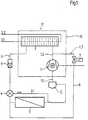
- the electric heat pump according to the invention is made in a manner known per se from a compressor 1, a condenser 2, a evaporator 3 and a thermostatically controlled expansion valve 4 constructed as main components.
- the arrangement also includes the supply of the liquid refrigerant via line 6 to the evaporator 3, a solenoid valve 7 in the supply line 8 of the hot, gaseous refrigerant also to the evaporator 3 for the purpose of defrosting it and a filter dryer interposed between the condenser 2 and in the supply line 6 9 as auxiliary components.
- a liquid separator 5 is connected upstream in the suction line 1.1.
- the housing 10 In the interior of the housing 10, preferably in a concentric position, there is a heat exchanger in the form of a coil of coils wound from a finned tube as a condenser 2.
- the compressor 1 is mounted inside the latter.
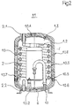
- the compressor 1 encapsulates the two system components 1 encapsulated in the pressure-resistant housing 10 and 2 together with their connecting lines form the capacitor module 11.
- the pressure-resistant housing 10 is also preferably surrounded by insulation 10.8 and has a heat and sound insulation.
- the pressure-resistant housing 10 can be inseparably welded together to form an encapsulation of the capacitor module 11, which is inaccessible throughout its useful life, from a aforementioned components, namely the base 10.2, the cylinder shell 10.3 and the cover 10.4.
- connection lines with the connections of the coolant circuit are marked in FIG. 2 with the following designations: 1.1 denotes a pipeline leading from the evaporator 3 to the liquid separator 5 and from there to the compressor 1, via which the compressor 1 sucks in the expanded, gaseous refrigerant from the evaporator 3.
- the Refrigerant compressed under high pressure emerges from the compressor 1 via the pipe section 1.2 into the interior of the housing 10 surrounding the condenser 2.
- the refrigerant condensed by giving off heat to the water flowing in the condenser 2 is collected at the deepest point of the bottom 10.2 which is curved downward. From there it comes to the connection of the pipeline 6 and the auxiliary components of the system arranged in the latter, but not shown in FIG.
- All of the connecting lines 1.1, 1.3, 6 of the condenser module 11 which run to the evaporator 3 and also the hot water line connections 2.1 and 2.2 are each equipped with a plug-in quick-action coupling which is expediently acted upon by the internal pressure prevailing therein and is therefore automatically secured and not shown in the drawing.
- the condenser module 11 or the integral electric heat pump module each represents a plug-in exchange unit.
- a feed cable (not shown) is required.
- the reference symbol 4.1 denotes the control line of the thermostatically controllable expansion valve 4.
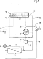
- the system and auxiliary components located outside the capacitor module 13 are the same as those in FIG. 1.
- the condenser 2 forms at least part of the housing 10, the inner wall 14 and / or the outer wall 15 having structures 14, for example ribs, which increase the surface area to ensure good heat transfer.
- This version also has the advantage that water connections leading into the interior of the pressure-resistant housing are eliminated, the condensation part or the structured inner wall still being located within the pressure-resistant housing.
- the modular electric compact heat pump described above is suitable as an exchange unit, especially in the transition period, for individual heating of single-family houses, for floor heating depending on the heat output required individually or in parallel (instead of a large heat pump), but also as a cooling unit with integral heat recovery . It is able to provide 50 to 70% of the annual heat requirement of modern buildings and can also be operated with a water or glycol evaporator instead of the air evaporator 3 shown here.
Landscapes
- Engineering & Computer Science (AREA)
- Physics & Mathematics (AREA)
- Mechanical Engineering (AREA)
- Thermal Sciences (AREA)
- General Engineering & Computer Science (AREA)
- Heat-Pump Type And Storage Water Heaters (AREA)
- Compressor (AREA)
- Electromagnetic Pumps, Or The Like (AREA)
Priority Applications (6)
| Application Number | Priority Date | Filing Date | Title |
|---|---|---|---|
| EP91104365A EP0504455A1 (de) | 1991-03-20 | 1991-03-20 | Elektro-Wärmepumpe und Kondensatormodul hierfür |
| HU9200708A HUT63698A (en) | 1991-03-20 | 1992-03-03 | Electric heat pump for heating heat-carrying media and condenser modular eleent belonging to same |
| SI9200031A SI9200031A (en) | 1991-03-20 | 1992-03-05 | Electric heat pump and a condenser module belonging to it |
| HRP920046AA HRP920046A2 (hr) | 1991-03-20 | 1992-03-19 | Elektro dizalica topline, kondenzatorski modul |
| CS92853A CS85392A3 (en) | 1991-03-20 | 1992-03-20 | Electric heat pump and a condenser module |
| PL29392392A PL293923A1 (en) | 1991-03-20 | 1992-03-20 | Electric heat pump, in particular condenser module of such pump |
Applications Claiming Priority (1)
| Application Number | Priority Date | Filing Date | Title |
|---|---|---|---|
| EP91104365A EP0504455A1 (de) | 1991-03-20 | 1991-03-20 | Elektro-Wärmepumpe und Kondensatormodul hierfür |
Publications (1)
| Publication Number | Publication Date |
|---|---|
| EP0504455A1 true EP0504455A1 (de) | 1992-09-23 |
Family
ID=8206549
Family Applications (1)
| Application Number | Title | Priority Date | Filing Date |
|---|---|---|---|
| EP91104365A Withdrawn EP0504455A1 (de) | 1991-03-20 | 1991-03-20 | Elektro-Wärmepumpe und Kondensatormodul hierfür |
Country Status (6)
| Country | Link |
|---|---|
| EP (1) | EP0504455A1 (cs) |
| CS (1) | CS85392A3 (cs) |
| HR (1) | HRP920046A2 (cs) |
| HU (1) | HUT63698A (cs) |
| PL (1) | PL293923A1 (cs) |
| SI (1) | SI9200031A (cs) |
Cited By (2)
| Publication number | Priority date | Publication date | Assignee | Title |
|---|---|---|---|---|
| WO2013113308A1 (de) * | 2012-02-02 | 2013-08-08 | Ixetic Bad Homburg Gmbh | Verdichter-wärmetauscher-einheit für ein heiz-kühl-modul für ein kraftfahrzeug |
| EP2923869A4 (en) * | 2012-11-20 | 2016-06-29 | Panasonic Ip Man Co Ltd | VEHICLE HEAT PUMP APPARATUS, AND VEHICLE AIR CONDITIONING APPARATUS |
Citations (10)
| Publication number | Priority date | Publication date | Assignee | Title |
|---|---|---|---|---|
| US1362757A (en) * | 1916-07-07 | 1920-12-21 | Stokes Douglas Henry | Refrigerating apparatus |
| CH168533A (it) * | 1932-05-16 | 1934-04-15 | An Zanchi Angeloni & C Success | Impianto frigorifero a comando elettrico con gruppo motocompressore ermeticamente chiuso. |
| US2121049A (en) * | 1925-10-20 | 1938-06-21 | Gen Motors Corp | Refrigeration apparatus |
| US2214086A (en) * | 1938-12-31 | 1940-09-10 | Gen Motors Corp | Refrigerating apparatus |
| US2288166A (en) * | 1940-12-23 | 1942-06-30 | Gen Motors Corp | Refrigerating apparatus |
| US2338953A (en) * | 1942-08-27 | 1944-01-11 | Gen Motors Corp | Refrigerating apparatus |
| US2518299A (en) * | 1945-06-16 | 1950-08-08 | Dan T Fernandez | Coupling and servicing assembly |
| FR1017516A (fr) * | 1950-03-07 | 1952-12-11 | Chambre froide et étuve combinées | |
| DE2922832A1 (de) * | 1979-06-05 | 1980-12-11 | Lth Tozd Z Za Hlajenje In Klim | Kondensationseinheit fuer eine waermepumpe |
| DE3441912A1 (de) * | 1984-11-16 | 1986-05-28 | Fichtel & Sachs Ag, 8720 Schweinfurt | Verfahren zum automatischen abtauen eines luftbeaufschlagten verdampfers einer waermepumpe |
-
1991
- 1991-03-20 EP EP91104365A patent/EP0504455A1/de not_active Withdrawn
-
1992
- 1992-03-03 HU HU9200708A patent/HUT63698A/hu unknown
- 1992-03-05 SI SI9200031A patent/SI9200031A/sl unknown
- 1992-03-19 HR HRP920046AA patent/HRP920046A2/hr not_active Application Discontinuation
- 1992-03-20 PL PL29392392A patent/PL293923A1/xx unknown
- 1992-03-20 CS CS92853A patent/CS85392A3/cs unknown
Patent Citations (10)
| Publication number | Priority date | Publication date | Assignee | Title |
|---|---|---|---|---|
| US1362757A (en) * | 1916-07-07 | 1920-12-21 | Stokes Douglas Henry | Refrigerating apparatus |
| US2121049A (en) * | 1925-10-20 | 1938-06-21 | Gen Motors Corp | Refrigeration apparatus |
| CH168533A (it) * | 1932-05-16 | 1934-04-15 | An Zanchi Angeloni & C Success | Impianto frigorifero a comando elettrico con gruppo motocompressore ermeticamente chiuso. |
| US2214086A (en) * | 1938-12-31 | 1940-09-10 | Gen Motors Corp | Refrigerating apparatus |
| US2288166A (en) * | 1940-12-23 | 1942-06-30 | Gen Motors Corp | Refrigerating apparatus |
| US2338953A (en) * | 1942-08-27 | 1944-01-11 | Gen Motors Corp | Refrigerating apparatus |
| US2518299A (en) * | 1945-06-16 | 1950-08-08 | Dan T Fernandez | Coupling and servicing assembly |
| FR1017516A (fr) * | 1950-03-07 | 1952-12-11 | Chambre froide et étuve combinées | |
| DE2922832A1 (de) * | 1979-06-05 | 1980-12-11 | Lth Tozd Z Za Hlajenje In Klim | Kondensationseinheit fuer eine waermepumpe |
| DE3441912A1 (de) * | 1984-11-16 | 1986-05-28 | Fichtel & Sachs Ag, 8720 Schweinfurt | Verfahren zum automatischen abtauen eines luftbeaufschlagten verdampfers einer waermepumpe |
Cited By (5)
| Publication number | Priority date | Publication date | Assignee | Title |
|---|---|---|---|---|
| WO2013113308A1 (de) * | 2012-02-02 | 2013-08-08 | Ixetic Bad Homburg Gmbh | Verdichter-wärmetauscher-einheit für ein heiz-kühl-modul für ein kraftfahrzeug |
| CN104094068A (zh) * | 2012-02-02 | 2014-10-08 | 麦格纳动力系巴德霍姆堡有限责任公司 | 用于机动车的加热冷却模块的压缩机换热器单元 |
| CN104094068B (zh) * | 2012-02-02 | 2016-10-19 | 麦格纳动力系巴德霍姆堡有限责任公司 | 用于机动车的加热冷却模块的压缩机换热器单元 |
| US9551516B2 (en) | 2012-02-02 | 2017-01-24 | Magna Powertrain Bad Homburg GmbH | Compressor-heat exchanger unit for a heating-cooling module for a motor vehicle |
| EP2923869A4 (en) * | 2012-11-20 | 2016-06-29 | Panasonic Ip Man Co Ltd | VEHICLE HEAT PUMP APPARATUS, AND VEHICLE AIR CONDITIONING APPARATUS |
Also Published As
| Publication number | Publication date |
|---|---|
| HU9200708D0 (en) | 1992-05-28 |
| SI9200031A (en) | 1992-11-27 |
| PL293923A1 (en) | 1993-04-19 |
| CS85392A3 (en) | 1992-11-18 |
| HUT63698A (en) | 1993-09-28 |
| HRP920046A2 (hr) | 1994-04-30 |
Similar Documents
| Publication | Publication Date | Title |
|---|---|---|
| EP3444542B1 (de) | Kreislaufsystem für ein fahrzeug und verfahren dazu | |
| DE69626595T2 (de) | Verflüssiger mit einem Flüssigkeitsbehälter | |
| DE19635454A1 (de) | Sammler-Wärmeübertrager-Baueinheit und damit ausgerüstete Klimaanlage | |
| DE102020120772A1 (de) | Verdichtermodul | |
| EP3648997A1 (de) | Kälteanlage für ein fahrzeug mit einem einen wärmeübertrager aufweisenden kältemittelkreislauf sowie wärmeübertrager für eine solche kälteanlage | |
| DE102009021442A1 (de) | Verteiltes Kühlsystem | |
| DE202009001056U1 (de) | Heizkreisverteiler | |
| DE2749072A1 (de) | Integrierte regeleinrichtung fuer ein heiz- und kuehlsystem | |
| WO2023020855A1 (de) | Modulbaugruppe für einen kältemittelkreis eines kraftfahrzeugs und kältemittelkreis | |
| DE69617164T2 (de) | Vorrichtung zur Beheizung/Klimatisierung eines Innenraumes von einem Fahrzeug mit Elektromotor | |
| DE102004005540A1 (de) | Wärmepumpenvorrichtung | |
| DE69516940T2 (de) | Sammler für eine Klimaanlage | |
| DE10162785B4 (de) | Ventilkombination für einen Fluidkreislauf mit zwei Druckniveaus, insbesondere für einen kombinierten Kälteanlagen/Wärmepumpenkreislauf | |
| DE19509536A1 (de) | Kältemittelaufnahmetank-Baueinheit | |
| EP0370262B1 (de) | Elektronisch steuerbares Regelventil | |
| DE19535291C1 (de) | Klimatisierungsanordnung für Nutzfahrzeuge, insbesondere Omnibusse | |
| EP0504455A1 (de) | Elektro-Wärmepumpe und Kondensatormodul hierfür | |
| DE8712814U1 (de) | Meßgaskühleinrichtung | |
| DE60314547T2 (de) | Speicher mit internem Trockenmittel | |
| DE112017002894B4 (de) | Schaltventil | |
| DE2700893C2 (de) | Kältemittelkreislauf für eine Wärmepumpe mit einem parallelepipedförmigen Gehäuse | |
| DE102020213544A1 (de) | Gaskältemaschine, Verfahren zum Betreiben einer Gaskältemaschine und Verfahren zum Herstellen einer Gaskältemaschine mit einem Rekuperator um den Ansaugbereich | |
| DE102004059782A1 (de) | Fluidkreissystem | |
| EP1174164B1 (de) | Container mit Energieversorgung und/oder Klimaanlage | |
| EP2530409A2 (de) | Wärmepumpenanlage sowie Verfahren zum Betrieb einer Wärmepumpenanlage |
Legal Events
| Date | Code | Title | Description |
|---|---|---|---|
| PUAI | Public reference made under article 153(3) epc to a published international application that has entered the european phase |
Free format text: ORIGINAL CODE: 0009012 |
|
| AK | Designated contracting states |
Kind code of ref document: A1 Designated state(s): AT BE CH DE DK ES FR GB GR IT LI LU NL SE |
|
| 17P | Request for examination filed |
Effective date: 19930318 |
|
| 17Q | First examination report despatched |
Effective date: 19940121 |
|
| STAA | Information on the status of an ep patent application or granted ep patent |
Free format text: STATUS: THE APPLICATION IS DEEMED TO BE WITHDRAWN |
|
| 18D | Application deemed to be withdrawn |
Effective date: 19940802 |