EP0503494B1 - Hubbett, insbesondere für Motorcaravans - Google Patents
Hubbett, insbesondere für Motorcaravans Download PDFInfo
- Publication number
- EP0503494B1 EP0503494B1 EP92103840A EP92103840A EP0503494B1 EP 0503494 B1 EP0503494 B1 EP 0503494B1 EP 92103840 A EP92103840 A EP 92103840A EP 92103840 A EP92103840 A EP 92103840A EP 0503494 B1 EP0503494 B1 EP 0503494B1
- Authority
- EP
- European Patent Office
- Prior art keywords
- rail
- fold
- lifting bed
- bed
- arm
- Prior art date
- Legal status (The legal status is an assumption and is not a legal conclusion. Google has not performed a legal analysis and makes no representation as to the accuracy of the status listed.)
- Expired - Lifetime
Links
Images
Classifications
-
- B—PERFORMING OPERATIONS; TRANSPORTING
- B60—VEHICLES IN GENERAL
- B60P—VEHICLES ADAPTED FOR LOAD TRANSPORTATION OR TO TRANSPORT, TO CARRY, OR TO COMPRISE SPECIAL LOADS OR OBJECTS
- B60P3/00—Vehicles adapted to transport, to carry or to comprise special loads or objects
- B60P3/32—Vehicles adapted to transport, to carry or to comprise special loads or objects comprising living accommodation for people, e.g. caravans, camping, or like vehicles
- B60P3/36—Auxiliary arrangements; Arrangements of living accommodation; Details
- B60P3/38—Sleeping arrangements, e.g. living or sleeping accommodation on the roof of the vehicle
Definitions
- the invention relates to a fold-down bed of the type described in the preamble of claim 1 (see for example DE-A-3 319 621).
- fold-down bed It can be provided for one or more people and has a grate or similar support surface for a cushion as the basic element.
- the peculiarity of such a fold-down bed is that it does not stand on the floor, but is suspended on swivel arms and can be swiveled up into a parallel or inclined storage position so that the space underneath is accessible or otherwise available.
- fold-down beds are used primarily in vehicles, e.g. B. caravan used.
- the lying surfaces of fold-down beds also usually have a considerable height in the use position. Therefore, it is known to arrange a railing of at least about 20 cm high on the long side of the lying surface facing away from the wall, which prevents a person from sleeping rolls out of the side of the bed and falls down. The railing is annoying, however, if the fold-down bed is raised to the ceiling for storage. It is therefore also known to mount the guardrail pivotable about an axis parallel to the longitudinal edge of the lying surface in such a way that it can be folded down from the operative position perpendicular to the lying surface towards the lying surface into a storage position. To use such a fold-down bed, two steps are necessary: First, the bed must be swung down from the storage position and then the guardrail must be folded up.
- the invention has for its object to simplify the handling of such a lifting bed, d. H. Reduce the number of operations when using and storing the lift bed.
- a particularly expedient embodiment of the invention consists in that the railing, which may consist, for example, of a pipe bend or a frame, is firmly connected to the swivel arm in question or better, the two swivel arms on the railing side. However, this presupposes the coincidence of the direction of rotation of the relevant swivel arms and the railing. If the direction of rotation is opposite, the railing with the swivel arms can also be geared, e.g. B. connected via gears.
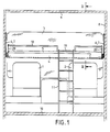
- FIG. 1 shows the front area of the vehicle designed with a full box body.
- the driver's seat is 1 on the left and the passenger seat 2 on the right.
- the windshield is labeled 3.
- Above this driver area there is a fold-down bed with a carrying trough 4 and a bed cushion 5.
- the carrying trough 4 is suspended from the head and foot end walls with two swivel arms 6, 7 each on the vehicle side walls 8. As a result, the bed can be pivoted towards the roof 9 while in a storage position.
- Fig. 1 shows the position of use.
- the lying surface is approximately 1.6 m above the vehicle floor 10 and can be reached by means of an employed ladder 11.
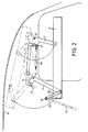
- Fig. 2 shows the suspension mechanism in detail.
- the storage position is indicated by dash-dotted lines.
- the longer swivel arm 6 and the short swivel arm 7 made of sheet metal both have an L-shaped cut. They are pivotally mounted at the corners at 12 and 13 on the wall and are also pivotally connected with their lower ends to the relevant end wall of the carrying trough 4. Both short legs of the swivel arms are connected to one another via a coupling 14.
- the wider short leg of the swivel arm 7 also has a second articulation point 15 for a gas pressure spring 16, which is mounted on the wall at the other end. It makes it easier to swing up the fold-down bed.
- the short leg of the long swivel arm 6 lies against one Stop 17.
- the fold-down bed is held by the gas pressure spring 16 and a locking mechanism, not shown.
- a railing is attached to the longitudinal side facing the vehicle interior. It consists of a straight railing tube 18, which has a U-shaped double bend 19 for easier entry. The hook-shaped upper spar ends of the ladder 11 are also hooked into this. Flat arms 20 are firmly attached to the ends of the railing tube 18, which in turn are firmly connected to the long swivel arms 6. This latter connection is realized in such a way that the lower pivot pins of the pivot arms 6 pass through the end walls of the carrying trough 4 and are firmly connected to the arms 20 on the inside.
Landscapes
- Engineering & Computer Science (AREA)
- Health & Medical Sciences (AREA)
- Public Health (AREA)
- Transportation (AREA)
- Mechanical Engineering (AREA)
- Seats For Vehicles (AREA)
- Fittings On The Vehicle Exterior For Carrying Loads, And Devices For Holding Or Mounting Articles (AREA)
- Vehicle Step Arrangements And Article Storage (AREA)
Description
- Die Erfindung betrifft ein Hubbett der im Oberbegriff des Patentanspruchs 1 bezeichneten Gattung (siche zum Beispiel DE-A-3 319 621).
- Es kann für eine oder mehrere Personen vorgesehen sein und hat als Grundelement einen Rost oder ähnliche Auflagefläche für ein Polster. Die Besonderheit eines solchen Hubbetts besteht darin, daß es nicht auf dem Boden steht, sondern an Schwenkarmen aufgehängt ist und mit deren Hilfe in eine parallele oder schräge Aufbewahrungsstellung so hochgeschwenkt werden kann, daß der Raum darunter begehbar oder jedenfalls anderweitig verfügbar wird. Aus Platzgründen werden Hubbetten vor allem bei Fahrzeugen, z. B. Wohnwagen, verwendet.
- Auch in der Gebrauchsstellung haben die Liegeflächen von Hubbetten normalerweise eine beträchtliche Höhe. Deshalb ist es bekannt, an der von der Wand abgewendeten Längsseite der Liegefläche ein Geländer von mindestens etwa 20 cm Höhe anzuordnen, welches verhindert, daß eine Person im Schlaf seitlich aus dem Bett rollt und herunterfällt. Das Geländer stört aber, wenn das Hubbett zur Aufbewahrung ganz an die Decke gehoben wird. Es ist daher ferner schon bekannt, das Schutzgeländer um eine zur Längskante der Liegefläche parallele Achse derart schwenkbar zu lagern, daß es aus der zur Liegefläche senkrechten Wirkstellung zur Liegefläche hin in eine Aufbewahrungsstellung umgeklappt werden kann. Um ein derartiges Hubbett in Benutzung zu nehmen, sind also zwei Handgriffe nötig: Zuerst ist das Bett aus der Aufbewahrungsstellung herunterzuschwenken und dann ist das Schutzgeländer hochzuklappen.
- Der Erfindung liegt die Aufgabe zugrunde, die Handhabung eines solchen Hubbetts zu vereinfachen, d. h. die Anzahl der Betätigungsvorgänge bei der Inbenutzungnahme und beim Aufbewahren des Hubbetts zu verringern.
- Diese Aufgabe wird erfindungsgemäß durch die im kennzeichnenden Teil des Patentanspruchs 1 angegebenen Merkmale gelöst. Es ist demnach nicht mehr erforderlich, das Schutzgeländer aufzustellen oder umzulegen, vielmehr wird diese Bewegung von den jeweiligen Schwenkarmen beim Verschwenken des Hubbetts selbsttätig ausgeführt. Nach dem Herabschwenken des Hubbetts in die Gebrauchsstellung kann es unmittelbar bestiegen werden.
- Eine besonders zweckmäßige Ausführungsform der Erfindung besteht darin, daß das Geländer, welches beispielsweise aus einem Rohrbogen oder einem Rahmen bestehen kann, mit dem betreffenden Schwenkarm oder besser den beiden geländerseitigen Schwenkarmen fest verbunden ist. Das setzt allerdings die Übereinstimmung des Drehsinns der betreffenden Schwenkarme und des Geländers voraus. Ist der Drehsinn entgegengesetzt, so kann das Geländer mit den Schwenkarmen auch getrieblich, z. B. über Zahnräder verbunden sein.
- Im folgenden Ausführungsbeispiel soll die Erfindung anhand einer Zeichnung näher erläutert werden. Im einzelnen zeigen
- Fig. 1
- einen Querschnitt eines Motorcaravan-Aufbaues in Fahrtrichtung gesehen und
- Fig. 2
- einen Teillängsschnitt II-II gemäß Fig. 1.
- Fig. 1 zeigt den vorderen Bereich des mit einem Ganzkofferaufbau gestalteten Fahrzeugs. Links ist der Fahrersitz 1 und rechts der Beifahrersitz 2. Die Windschutzscheibe ist mit 3 bezeichnet. Über diesem Fahrerbereich befindet sich ein Hubbett mit einer Tragwanne 4 und einem Liegepolster 5. Die Tragwanne 4 ist an ihren kopf- und fußseitigen Stirnwänden mit je zwei Schwenkarmen 6, 7 an den Fahrzeugseitenwänden 8 aufgehängt. Dadurch kann das Bett während der Fahrt in eine Aufbewahrungsstellung an das Dach 9 herangeschwenkt werden. Fig. 1 zeigt die Gebrauchsstellung. Hierbei befindet sich die Liegefläche etwa 1,6 m über dem Fahrzeugboden 10 und kann mittels einer angestellten Leiter 11 erreicht werden.
- Fig. 2 zeigt den Aufhängemechanismus im einzelnen. Hier ist die Aufbewahrungsstellung strichpunktiert angedeutet. Der längere Schwenkarm 6 und der kürze Schwenkarm 7 aus Blech haben beide einen L-förmigen Zuschnitt. Sie sind an den Ecken bei 12 und 13 schwenkbar an der Wand gelagert und mit ihren unteren Enden ebenfalls schwenkbar mit der betreffenden Stirnwand der Tragwanne 4 verbunden. Beide kurzen Schenkel der Schwenkarme sind über eine Koppel 14 miteinander verbunden. Der breitere kurze Schenkel des Schwenkarms 7 hat außerdem noch einen zweiten Anlenkpunkt 15 für eine Gasdruckfeder 16, die anderenends an der Wand gelagert ist. Sie erleichtert das Hochschwenken des Hubbetts. In der mit ausgezogenen Strichen dargestellten Gebrauchsstellung legt sich der kurze Schenkel des langen Schwenkarms 6 an einen Anschlag 17. In der Aufbewahrungsstellung wird das Hubbett durch die Gasdruckfeder 16 und einen nicht dargestellten Verriegelungsmechanismus gehalten.
- Wie bei derartigen, verhältnismäßig hoch über dem Fußboden angeordneten Betten üblich, ist an der dem Fahrzeuginnenraum zugewandten Längsseite ein Geländer angebracht. Es besteht aus einem geraden Geländerrohr 18, das zum leichteren Einstieg eine U-förmige doppelte Abkröpfung 19 aufweist. In diese werden auch die hakenförmigen oberen Holmenden der Leiter 11 eingehängt. An den Enden des Geländerrohrs 18 sind flache Arme 20 fest angebracht, die wiederum mit den langen Schwenkarmen 6 fest verbunden sind. Diese letztere Verbindung ist derart verwirklicht, daß die unteren Schwenkzapfen der Schwenkarme 6 die Stirnwände der Tragwanne 4 durchsetzen und an der Innenseite mit den Armen 20 fest verbunden sind.
- Das hat, wie Fig. 2 zeigt, zur Folge, daß beim Hochschwenken des Hubbetts in die Aufbewahrungsstellung infolge der Bewegungen der Schwenkarme 6 bezüglich der Tragwanne 4 gleichzeitig die Arme 20 mitverschwenkt werden. Das Geländerrohr 18 schwenkt also zur Liegefläche hin und legt sich auf diese, so daß das Bett bis zur Berührung an das Fahrzeugdach herangebracht werden kann, ohne daß das Geländerrohr 18 stört. Beim Herabschwenken in die Benutzungsstellung richtet sich das Geländer selbsttätig wieder auf und erfüllt seine Schutzfunktion, ohne daß es eines besonderen Handgriffs bedarf.
- 1
- Fahrersitz
- 2
- Beifahrersitz
- 3
- Windschutzscheibe
- 4
- Tragwanne
- 5
- Liegepolster
- 6
- langer Schwenkarm
- 7
- kurzer Schwenkarm
- 8
- Seitenwand
- 9
- Dach
- 10
- Boden
- 11
- Leiter
- 12
- Drehpunkt
- 13
- Drehpunkt
- 14
- Koppel
- 15
- Anlenkpunkt
- 16
- Gasdruckfeder
- 17
- Anschlag
- 18
- Geländerrohr
- 19
- Abkröpfung
- 20
- Arm
Claims (3)
- Hubbett, das mit Hilfe von je zwei mit längsgerichteten Achsen am Kopf- und Fußende angelenkten Schwenkarmen (6, 7) zwischen einer unteren Gebrauchsstellung und einer oberen Aufbewahrungsstellung verschwenkbar ist, und das ein längs der freien Längskante der Liegefläche angeordnetes, zur Liegefläche hin umlegbares Geländer (18-20) aufweist, insbesondere zum Einbau über dem Fahrer- und Beifahrersitz eines Motorcaravans mit Ganzkofferaufbau, dadurch gekennzeichnet, daß wenigstens einer der beiden geländerseitigen Schwenkarme (6) mit dem Geländer (18, 20) derart gekoppelt ist, daß beim Verschwenken des Hubbetts in die Gebrauchsstellung das Geländer von dem Schwenkarm (6) in die wirksame Stellung hochgeklappt und bei der entgegengesetzten Schwenkbewegung umgelegt wird.
- Hubbett nach Anspruch 1, dadurch gekennzeichnet, daß das Geländer (18, 20) mit dem betreffenden Schwenkarm (6) fest verbunden ist.
- Hubbett nach Anspruch 1, dadurch gekennzeichnet, daß das Geländer mit dem betreffenden Schwenkarm getrieblich verbunden ist.
Applications Claiming Priority (2)
| Application Number | Priority Date | Filing Date | Title |
|---|---|---|---|
| DE4107407A DE4107407A1 (de) | 1991-03-08 | 1991-03-08 | Hubbett, insbesondere fuer motorcaravans |
| DE4107407 | 1991-03-08 |
Publications (2)
| Publication Number | Publication Date |
|---|---|
| EP0503494A1 EP0503494A1 (de) | 1992-09-16 |
| EP0503494B1 true EP0503494B1 (de) | 1994-07-13 |
Family
ID=6426748
Family Applications (1)
| Application Number | Title | Priority Date | Filing Date |
|---|---|---|---|
| EP92103840A Expired - Lifetime EP0503494B1 (de) | 1991-03-08 | 1992-03-06 | Hubbett, insbesondere für Motorcaravans |
Country Status (2)
| Country | Link |
|---|---|
| EP (1) | EP0503494B1 (de) |
| DE (2) | DE4107407A1 (de) |
Families Citing this family (6)
| Publication number | Priority date | Publication date | Assignee | Title |
|---|---|---|---|---|
| DE9417643U1 (de) * | 1994-02-18 | 1995-01-05 | Grasse, Eckart, Dipl.-Ing. (FH), 82544 Egling | Wohn- oder Reisemobil mit geschlossenem Kastenaufbau |
| DE19919657A1 (de) * | 1999-04-29 | 2000-11-02 | Man Nutzfahrzeuge Ag | Verschwenkbare Herausfallsicherung für Liegen in Nutzfahrzeugen oder Wohnmobilen |
| GB0709335D0 (en) * | 2007-05-15 | 2007-06-20 | Autochaise | Improvements in a motorised passenger cabin fold away bunk-bed |
| ITPI20110073A1 (it) * | 2011-07-01 | 2013-01-02 | St La Srl | Dispositivo di sollevamento del tipo a forbice, per letti di veicoli ricreativi. |
| DE102014000724B4 (de) * | 2014-01-23 | 2016-07-28 | Hymer-Leichtmetallbau Gmbh & Co. Kg | Hubbett für Land-, Wasser- und Luftfahrzeuge mit Betätigungseinrichtung |
| CN111772414B (zh) * | 2020-07-17 | 2022-08-19 | 吉荣家具有限公司 | 一种带有储物箱的学生床 |
Family Cites Families (10)
| Publication number | Priority date | Publication date | Assignee | Title |
|---|---|---|---|---|
| AT125308B (de) * | 1930-12-03 | 1931-11-10 | Automobilfabrik Perl Ag | Einrichtung an Kraftwagenkarosserien, insbesondere für Lastwagen und Autobusse. |
| US2583760A (en) * | 1948-09-24 | 1952-01-29 | Simmons Co | Guard rail for folding berths |
| AT170672B (de) * | 1949-07-13 | 1952-03-10 | Anton Foelsch | Verstellbare Schlafbetten, insbesondere für Kraftfahrzeuge |
| DE1630334B2 (de) * | 1967-08-08 | 1973-05-17 | Daimler Benz Ag, 7000 Stuttgart | Schlafstellenanordnung fuer lastkraftwagen |
| DE6813582U (de) * | 1968-12-20 | 1969-05-08 | Juvenilia Sa | Schrankbett |
| DE7737023U1 (de) * | 1977-12-05 | 1978-03-30 | Westfalia-Werke Franz Knoebel & Soehne Kg, 4832 Rheda-Wiedenbrueck | Beschlag für verwandelbare Sitze |
| DE7909760U1 (de) * | 1979-04-04 | 1979-12-13 | Schlapp Moebel Gmbh & Co Kg Moebelfabrikation, 6392 Neu-Anspach | Etagenbett mit leiter mit fallschutzrahmen |
| ES245045Y (es) * | 1979-08-06 | 1980-05-16 | Litera abatible perfeccionada | |
| DE8103431U1 (de) * | 1981-02-10 | 1981-08-13 | Tabbert Wohnwagenwerke Gmbh, 8730 Bad Kissingen | Wohnwagen, Wohnmobil o.dgl. |
| DE3319621A1 (de) * | 1983-05-30 | 1984-12-06 | Siegfried 2800 Bremen Binder | Feste schlafeinrichtung fuer wohnwagen insbesondere fuer wohnmobile |
-
1991
- 1991-03-08 DE DE4107407A patent/DE4107407A1/de not_active Withdrawn
-
1992
- 1992-03-06 DE DE59200271T patent/DE59200271D1/de not_active Expired - Fee Related
- 1992-03-06 EP EP92103840A patent/EP0503494B1/de not_active Expired - Lifetime
Also Published As
| Publication number | Publication date |
|---|---|
| DE59200271D1 (de) | 1994-08-18 |
| DE4107407A1 (de) | 1992-09-10 |
| EP0503494A1 (de) | 1992-09-16 |
Similar Documents
| Publication | Publication Date | Title |
|---|---|---|
| DE2739415C2 (de) | Schlafeinrichtung in Fernfahrerhäusern für Lastkraftwagen mit Wohnwageneinbauten | |
| DE60304991T2 (de) | Kopfstütze für kraftfahrzeuge | |
| DE68929186T2 (de) | Fahrzeuge und Ladebordwände | |
| DE69406718T2 (de) | Mehrfachsitz für Kraftfahrzeuge | |
| DE102007042371A1 (de) | Höhenverstellvorrichtung für den Ladeboden eines Kraftfahrzeugs | |
| DE68909281T2 (de) | Verstellbare Säule für ein Lastkraftfahrzeug mit verschiebbarer Abdeckung. | |
| EP0221911B1 (de) | Wagenheber | |
| EP0861165A1 (de) | Klappsitzbank | |
| EP0970844A1 (de) | Sitzmodul | |
| EP1754628A2 (de) | Wohnmobil mit einem Hubbett | |
| DE202007016357U1 (de) | Kraftfahrzeugsitz | |
| EP0503494B1 (de) | Hubbett, insbesondere für Motorcaravans | |
| DE3505047C2 (de) | ||
| DE2709005B2 (de) | Fahrzeugsitz, insbesondere in Kraftfahrzeugen | |
| DE60025894T2 (de) | Hintere Bodenwanne für Kraftfahrzeuge | |
| EP0221229B1 (de) | Polstersitz, insbesondere für den Einbau in ein als Multimobil ausgelegtes Kraftfahrzeug | |
| DE69516819T2 (de) | Ladevorrichtung für Fahrzeuge und mit derselben versehene Fahrzeuge | |
| DE3446523C2 (de) | ||
| EP3950419B1 (de) | Fahrzeugsitz | |
| DE20118211U1 (de) | Vorrichtung zur Betätigung eines Hubbettes | |
| EP0415041B1 (de) | Schlafliege im Fahrerhaus eines LKW's | |
| DE4111634C2 (de) | Sitzanordnung für ein Kraftfahrzeug mit herausnehmbarem Sitz | |
| EP1516780B1 (de) | Liege für ein LKW-Fahrerhaus | |
| EP0525618A2 (de) | Sitzbank für Reisemobile, Transporter od.dgl | |
| DE9106344U1 (de) | Reisefahrzeug |
Legal Events
| Date | Code | Title | Description |
|---|---|---|---|
| PUAI | Public reference made under article 153(3) epc to a published international application that has entered the european phase |
Free format text: ORIGINAL CODE: 0009012 |
|
| AK | Designated contracting states |
Kind code of ref document: A1 Designated state(s): BE DE FR GB IT NL |
|
| 17P | Request for examination filed |
Effective date: 19930315 |
|
| 17Q | First examination report despatched |
Effective date: 19931216 |
|
| GRAA | (expected) grant |
Free format text: ORIGINAL CODE: 0009210 |
|
| AK | Designated contracting states |
Kind code of ref document: B1 Designated state(s): BE DE FR GB IT NL |
|
| REF | Corresponds to: |
Ref document number: 59200271 Country of ref document: DE Date of ref document: 19940818 |
|
| GBT | Gb: translation of ep patent filed (gb section 77(6)(a)/1977) |
Effective date: 19940824 |
|
| ITF | It: translation for a ep patent filed | ||
| ET | Fr: translation filed | ||
| PLBE | No opposition filed within time limit |
Free format text: ORIGINAL CODE: 0009261 |
|
| STAA | Information on the status of an ep patent application or granted ep patent |
Free format text: STATUS: NO OPPOSITION FILED WITHIN TIME LIMIT |
|
| 26N | No opposition filed | ||
| PGFP | Annual fee paid to national office [announced via postgrant information from national office to epo] |
Ref country code: GB Payment date: 19960301 Year of fee payment: 5 |
|
| PGFP | Annual fee paid to national office [announced via postgrant information from national office to epo] |
Ref country code: BE Payment date: 19960320 Year of fee payment: 5 |
|
| PGFP | Annual fee paid to national office [announced via postgrant information from national office to epo] |
Ref country code: FR Payment date: 19960328 Year of fee payment: 5 |
|
| PGFP | Annual fee paid to national office [announced via postgrant information from national office to epo] |
Ref country code: NL Payment date: 19960330 Year of fee payment: 5 |
|
| PG25 | Lapsed in a contracting state [announced via postgrant information from national office to epo] |
Ref country code: GB Effective date: 19970306 |
|
| PG25 | Lapsed in a contracting state [announced via postgrant information from national office to epo] |
Ref country code: BE Effective date: 19970331 |
|
| BERE | Be: lapsed |
Owner name: DETHLEFFS G.M.B.H. Effective date: 19970331 |
|
| PG25 | Lapsed in a contracting state [announced via postgrant information from national office to epo] |
Ref country code: NL Effective date: 19971001 |
|
| GBPC | Gb: european patent ceased through non-payment of renewal fee |
Effective date: 19970306 |
|
| PG25 | Lapsed in a contracting state [announced via postgrant information from national office to epo] |
Ref country code: FR Free format text: LAPSE BECAUSE OF NON-PAYMENT OF DUE FEES Effective date: 19971128 |
|
| NLV4 | Nl: lapsed or anulled due to non-payment of the annual fee |
Effective date: 19971001 |
|
| REG | Reference to a national code |
Ref country code: FR Ref legal event code: ST |
|
| PGFP | Annual fee paid to national office [announced via postgrant information from national office to epo] |
Ref country code: DE Payment date: 19980418 Year of fee payment: 7 |
|
| PG25 | Lapsed in a contracting state [announced via postgrant information from national office to epo] |
Ref country code: DE Free format text: LAPSE BECAUSE OF NON-PAYMENT OF DUE FEES Effective date: 20000101 |
|
| PG25 | Lapsed in a contracting state [announced via postgrant information from national office to epo] |
Ref country code: IT Free format text: LAPSE BECAUSE OF NON-PAYMENT OF DUE FEES Effective date: 20050306 |