EP0502467B1 - Support pour étrangleur toroidal d'une fiche de secteur - Google Patents
Support pour étrangleur toroidal d'une fiche de secteur Download PDFInfo
- Publication number
- EP0502467B1 EP0502467B1 EP92103597A EP92103597A EP0502467B1 EP 0502467 B1 EP0502467 B1 EP 0502467B1 EP 92103597 A EP92103597 A EP 92103597A EP 92103597 A EP92103597 A EP 92103597A EP 0502467 B1 EP0502467 B1 EP 0502467B1
- Authority
- EP
- European Patent Office
- Prior art keywords
- plug
- assembly unit
- mounting
- toroidal core
- assembly
- Prior art date
- Legal status (The legal status is an assumption and is not a legal conclusion. Google has not performed a legal analysis and makes no representation as to the accuracy of the status listed.)
- Expired - Lifetime
Links
- 230000000295 complement effect Effects 0.000 claims description 7
- 238000001746 injection moulding Methods 0.000 claims description 2
- 230000036039 immunity Effects 0.000 claims 1
- 238000003780 insertion Methods 0.000 description 3
- 230000037431 insertion Effects 0.000 description 3
- 238000004519 manufacturing process Methods 0.000 description 3
- 239000011324 bead Substances 0.000 description 1
- 238000005538 encapsulation Methods 0.000 description 1
- 238000002347 injection Methods 0.000 description 1
- 239000007924 injection Substances 0.000 description 1
- 239000000463 material Substances 0.000 description 1
- 238000000034 method Methods 0.000 description 1
- 230000002093 peripheral effect Effects 0.000 description 1
- 229920000642 polymer Polymers 0.000 description 1
- 239000000243 solution Substances 0.000 description 1
Images

Classifications
-
- H—ELECTRICITY
- H01—ELECTRIC ELEMENTS
- H01R—ELECTRICALLY-CONDUCTIVE CONNECTIONS; STRUCTURAL ASSOCIATIONS OF A PLURALITY OF MUTUALLY-INSULATED ELECTRICAL CONNECTING ELEMENTS; COUPLING DEVICES; CURRENT COLLECTORS
- H01R13/00—Details of coupling devices of the kinds covered by groups H01R12/70 or H01R24/00 - H01R33/00
- H01R13/66—Structural association with built-in electrical component
- H01R13/6608—Structural association with built-in electrical component with built-in single component
- H01R13/6633—Structural association with built-in electrical component with built-in single component with inductive component, e.g. transformer
-
- H—ELECTRICITY
- H01—ELECTRIC ELEMENTS
- H01R—ELECTRICALLY-CONDUCTIVE CONNECTIONS; STRUCTURAL ASSOCIATIONS OF A PLURALITY OF MUTUALLY-INSULATED ELECTRICAL CONNECTING ELEMENTS; COUPLING DEVICES; CURRENT COLLECTORS
- H01R31/00—Coupling parts supported only by co-operation with counterpart
- H01R31/005—Intermediate parts for distributing signals
-
- H—ELECTRICITY
- H01—ELECTRIC ELEMENTS
- H01R—ELECTRICALLY-CONDUCTIVE CONNECTIONS; STRUCTURAL ASSOCIATIONS OF A PLURALITY OF MUTUALLY-INSULATED ELECTRICAL CONNECTING ELEMENTS; COUPLING DEVICES; CURRENT COLLECTORS
- H01R2103/00—Two poles
-
- H—ELECTRICITY
- H01—ELECTRIC ELEMENTS
- H01R—ELECTRICALLY-CONDUCTIVE CONNECTIONS; STRUCTURAL ASSOCIATIONS OF A PLURALITY OF MUTUALLY-INSULATED ELECTRICAL CONNECTING ELEMENTS; COUPLING DEVICES; CURRENT COLLECTORS
- H01R24/00—Two-part coupling devices, or either of their cooperating parts, characterised by their overall structure
- H01R24/28—Coupling parts carrying pins, blades or analogous contacts and secured only to wire or cable
-
- H—ELECTRICITY
- H01—ELECTRIC ELEMENTS
- H01R—ELECTRICALLY-CONDUCTIVE CONNECTIONS; STRUCTURAL ASSOCIATIONS OF A PLURALITY OF MUTUALLY-INSULATED ELECTRICAL CONNECTING ELEMENTS; COUPLING DEVICES; CURRENT COLLECTORS
- H01R43/00—Apparatus or processes specially adapted for manufacturing, assembling, maintaining, or repairing of line connectors or current collectors or for joining electric conductors
- H01R43/20—Apparatus or processes specially adapted for manufacturing, assembling, maintaining, or repairing of line connectors or current collectors or for joining electric conductors for assembling or disassembling contact members with insulating base, case or sleeve
- H01R43/24—Assembling by moulding on contact members
Definitions
- the present invention relates to a holder for a toroidal inductor integrated in the plug body of an electrical mains plug according to the preamble of patent claim 1.
- a power plug with an integrated holder or receptacle for the current-compensated toroidal choke is known in connection with a so-called central plug from DE-OS 34 40 573.
- the holder or receptacle for the toroidal core choke is designed together with the crossbar and the connector bridge as a one-piece molded part, the connector pins being inserted and fixed simultaneously with the injection molding of the connector bridge shape.
- the insertion of the contact sleeves, the insertion of the toroidal choke and the connection of the connecting wires of the toroidal core choke to the contact sleeves or the plug pins are then carried out in successive operations.
- the object underlying the present invention is now to provide a holder of the generic type with which the production can be optimized and maximized insofar as the individual operations for the completion of the basic unit consisting of crossbar, holder and plug bridge for the plug body each optimally can be done for yourself.
- the two assembly units are each prepared and completed for themselves so that the holder is only created when the two are assembled, into which the toroidal inductor is then inserted or clipped and connected, in particular squeezed, with respect to their connecting wires to the contact sleeves and the plug pins (crimped).
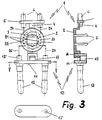
- This first assembly unit 1 essentially consists of a round plate 2, which - see FIG. 3 - serves as a receptacle or support for a toroidal core choke.
- the round plate 2 has two resilient hook elements 3 arranged diametrically to one another and projecting from the plane of the plate 2.
- a projecting web 4 adjoins the circumference, which in turn carries a cross web 5 at the end.
- This transverse web 5 is arranged transversely to the direction of the web 4 and has receiving bores for the contact sleeves 6 to be used in production.
- a block 7 which also projects outwards and has a particularly rectangular opening 8 at a distance from the round plate 2.
- the first assembly unit 1 described so far is manufactured as a separate molded part and is equipped as an individual part with the contact sleeves 6 and connected, in particular crimped, to the cable wires of the connecting cable.
- FIG. 2 shows the second assembly unit 10, the essential component of which is a rigid, approximately slot-shaped (see FIG. 3) connector bridge 11 with molded connector pins 12.
- the connector pins 12 are molded as is known so that they protrude on both sides of the plug bridge 11 - on the one hand, the plug pins that can be inserted into a power socket protrude and, on the other hand, these plug pins protrude from the back of the plug bridge 11 and offer a hollow cylindrical receptacle 12 'for the connecting wires the toroidal choke (see Fig. 3).
- the plug bridge 11 additionally has a bridge-like projection 13 centrally between the latter hollow cylindrical receptacles 12 '.
- This projection 13 extends approximately to half the connector bridge width and merges into a nose-like extension 14 at a distance from the connector bridge 11, the cross section of which is designed and dimensioned to be complementary to the opening (8 in FIG. 1) in the block (7 in FIG. 1) .
- FIG. 3 shows the mounting 20 consisting of the assembled mounting units 1 and 10 and completed in three views.
- the bracket 20 is first assembled in that the first assembly unit 1 with its opening 8 is plugged onto the complementary nose-like extension 14 of the second assembly unit 10. This gives a positive connection between these two assembly units 1 and 10 and a one-piece assembly body for final assembly and final production.
- This completion now consists in that a toroidal core choke 21 with its two coils 22, 23 is placed over the hook elements 3 of the first assembly unit 1 and is thus placed on the round plate 2.
- the connecting wire pairs 24/25, 26/27 projecting from the coils 22, 23 are then connected, in particular crimped, to the corresponding contact sleeves 6 or hollow cylindrical receptacles 12 'of the connector pins 12.
- the holder 20 thus completed is then finally placed in an injection mold and overmolded with plastic - the product is then a plug with two plug pins for insertion into a mains socket and a connecting cable (connected to the contact sleeves).
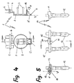
- FIGS. 4 and 5 A second exemplary embodiment of the assembly units 1 and 10 will be explained with reference to FIGS. 4 and 5. Relative to the (first) embodiment of the holder according to the invention shown in FIGS. 1 to 3, the difference and advantage is that the holder according to the second embodiment - Viewed axially - builds shorter because the projection of the second mounting unit 10 is integrated in the region of the plug bridge 11. This has the advantage that material can be saved overall.
- FIG. 4 shows - in analogy to FIG. 1 - a first assembly unit 1 with a round plate 2 for receiving a toroidal core choke between the resilient hook elements 3.
- the round plate 2 cries on one side the projecting web 4 with the cross web 5 and the contact sleeves 6 on.
- a protruding projection or block 7 ' is provided in the same way as in the exemplary embodiment according to FIG. 1, which also comprises a rectangular opening 8'.
- the extension 7 ' is stepped towards the outside, so that only a narrow web 9 remains as the outer boundary of the opening 8'.
- the connector bridge 11 lies against this narrow web 9 laterally.
- the second assembly unit 10 is provided on the inner peripheral bead of the opening 8 'protruding nose 16.
- Fig. 5 shows - in analogy to Fig. 2 - a second assembly unit 10. It consists of the connector bridge 11 with the molded connector pins 12 which protrude from the rear to the connector bridge 11 and provide a hollow cylindrical receptacle 12 'for the connecting wires of the toroidal choke.
- the complement to the opening 8 'or the approach 7' of the first assembly unit 1 is not formed as a projection (13 in Fig. 2), but as a laterally incorporated into the connector bridge 11 groove 15, the to the top with the contact sleeves 12 'is open. This results in a groove 15 which is open at the top on two sides and onto which the first assembly unit 1 with the web 9 and the adjacent sides can be attached. Through the groove 15, a projection 16 is formed, which engages positively during assembly in the opening 8 '.
- the two assembly units 1 and 10 explained with reference to FIGS. 4 and 5 are each manufactured individually. During assembly, both assembly units 1 and 10 are joined to one another or plugged onto one another (see arrow x) in such a way that the second assembly unit 10 in the region of the groove 15 and the projection 16 into the opening 8 'and on the narrow web 9 of the first assembly unit 1 is pushed. The plug bridge 11 then closes laterally with the base plane of the round plate 2 (cf. Y).
Landscapes
- Engineering & Computer Science (AREA)
- Power Engineering (AREA)
- Details Of Connecting Devices For Male And Female Coupling (AREA)
- Connector Housings Or Holding Contact Members (AREA)
Claims (5)
- Support pour étrangleur toroïdal (21) à courant compensé intégré dans le corps d'une fiche de secteur et servant à immuniser des appareils électriques contre les parasites, qui est relié, d'une part, à deux douilles de contact (6) immobilisées mécaniquement par une barrette transversale (5) qui sont destinées à recevoir les conducteurs d'un câble de raccordement électrique, et, d'autre part, à deux broches (12) immobilisées avec un écartement standard par un pont pour fiche (11),
sachant que l'unité constituée par la barrette transversale avec les douilles de contact et les extrémités des conducteurs du câble, par le support (2,3) avec l'étrangleur toroïdal et par le pont pour fiche est couverte de matière plastique par extrusion et forme un élément de préhension duquel partent, d'un côté, les broches pouvant être introduites dans une prise d'un réseau d'alimentation et, de l'autre côte, le câble de raccordement,
caractérisé en ce que
la barrette transversale (5) avec les douilles de contact (6) et les extrémités des conducteurs du câble ainsi que le support (2) avec l'étrangleur toroïdal (21) d'une part et le pont pour fiche (11) avec les broches (12) d'autre part forment chacun une unité de montage individuelle (1,10) qui sera assemblée à engagement positif avant d'être couverte de matière plastique. - Support selon la revendication 1,
caractérisé en ce que
les unités de montage (1,10) présentent des moyens de verrouillage complémentaires par lesquels elles peuvent être emboîtées. - Support selon la revendication 1 ou 2,
caractérisé en ce que
l'une des unités de montage (1,10) présente une pièce de raccord (7) avec perçage (8) orientée vers l'autre unité de montage et que cette autre unité de montage comprend une pièce conjuguée (13) avec une partie en saillie (14) réalisée de façon complémentaire par rapport au perçage (8). - Support selon la revendication 1 ou 2,
caractérisé en ce que
l'une des unités de montage (1) présente une pièce de raccord en saillie (7′) avec perçage (8′) du côté diamétralement opposé à la barrette transversale (5) et que l'autre unité de montage (10) présente une rainure (15) incorporée dans la zone d'un des côtés du pont pour fiche et ouverte vers le côté de devant du pont (11) muni de douilles de contact (12′)
de manière que cette autre unité de montage (10) avec le perçage (8′) puisse être introduite, par le biais de la rainure (15), dans une l'unité de montage (1). - Support selon la revendication 4,
caractérisé en ce que
la pièce de raccord (7′) présente, dans la zone du support (2) de l'étrangleur toroïdal (21), un talon (16) qui, lors du montage de l'unité (1,10), coïncide avec la face supérieure du pont pour fiche (11).
Applications Claiming Priority (4)
| Application Number | Priority Date | Filing Date | Title |
|---|---|---|---|
| DE4107302 | 1991-03-07 | ||
| DE4107302 | 1991-03-07 | ||
| DE4114036A DE4114036A1 (de) | 1991-03-07 | 1991-04-29 | Halterung fuer eine ringkerndrossel eines elektrischen netzsteckers |
| DE4114036 | 1991-04-29 |
Publications (2)
| Publication Number | Publication Date |
|---|---|
| EP0502467A1 EP0502467A1 (fr) | 1992-09-09 |
| EP0502467B1 true EP0502467B1 (fr) | 1994-10-12 |
Family
ID=25901654
Family Applications (1)
| Application Number | Title | Priority Date | Filing Date |
|---|---|---|---|
| EP92103597A Expired - Lifetime EP0502467B1 (fr) | 1991-03-07 | 1992-03-02 | Support pour étrangleur toroidal d'une fiche de secteur |
Country Status (2)
| Country | Link |
|---|---|
| EP (1) | EP0502467B1 (fr) |
| DE (2) | DE4114036A1 (fr) |
Families Citing this family (8)
| Publication number | Priority date | Publication date | Assignee | Title |
|---|---|---|---|---|
| DE4239818C2 (de) * | 1992-11-26 | 2001-11-29 | Epcos Ag | Bewickelter Ringkern |
| DE4402351C2 (de) * | 1994-01-27 | 1999-01-07 | Hans M Strassner | Vorrichtung zur Unterdrückung von Brumm- und eingestreuten Störungen auf Audio-Verbindungsleitungen |
| ES2102940B1 (es) * | 1994-04-13 | 1998-04-01 | Cablerias Conductoras Sa | Dispositivo de conexionado electrico por enchufe. |
| US6198643B1 (en) * | 1998-11-20 | 2001-03-06 | Audio Line Source, Llc | System with choke in parallel with A/C power line for load conditioning |
| DE29821736U1 (de) * | 1998-12-07 | 2000-04-13 | Robert Bosch Gmbh, 70469 Stuttgart | Handwerkzeugmaschine |
| DE202004014066U1 (de) | 2004-09-09 | 2004-12-16 | Vogt Electronic Aktiengesellschaft | Trägerbauteil und Entstördrosselvorrichtung |
| DE102010031292B4 (de) * | 2010-07-13 | 2020-06-18 | Würth Elektronik eiSos Gmbh & Co. KG | Halterung für eine Spule |
| DE102012107902A1 (de) * | 2012-08-28 | 2014-03-06 | Lapp Engineering & Co. | Steckereinheit und elektrisches Gerät mit einer derartigen Steckereinheit |
Citations (1)
| Publication number | Priority date | Publication date | Assignee | Title |
|---|---|---|---|---|
| EP0468314A1 (fr) * | 1990-07-27 | 1992-01-29 | Taller GmbH | Support pour étrangleur toroidal intégré dans le corps d'une fiche de secteur |
Family Cites Families (5)
| Publication number | Priority date | Publication date | Assignee | Title |
|---|---|---|---|---|
| DE7623595U1 (de) * | 1976-07-27 | 1978-03-09 | Karl Stolle, Kabel- Und Antennenfabrik, 4670 Luenen | Trafostecker |
| DE3379308D1 (en) * | 1982-03-26 | 1989-04-06 | Feller Ag | Device for protecting an electrical apparatus against disturbances |
| DE3440573A1 (de) * | 1984-11-07 | 1986-05-07 | Vogt electronic AG, 8391 Erlau | In einem eurostecker untergebrachte stromkompensierte drossel |
| DE3842038A1 (de) * | 1988-12-14 | 1990-06-21 | Vogt Electronic Ag | Steckerbruecke fuer europa-stecker mit integrierter einstroemdrossel |
| DE3922398A1 (de) * | 1989-07-07 | 1991-01-17 | Vogt Electronic Ag | Anschlusskabel mit integrierter drossel zur unterdrueckung der stoereinstrahlung an fernmeldetechnischen geraeten |
-
1991
- 1991-04-29 DE DE4114036A patent/DE4114036A1/de active Granted
-
1992
- 1992-03-02 EP EP92103597A patent/EP0502467B1/fr not_active Expired - Lifetime
- 1992-03-02 DE DE59200610T patent/DE59200610D1/de not_active Expired - Fee Related
Patent Citations (1)
| Publication number | Priority date | Publication date | Assignee | Title |
|---|---|---|---|---|
| EP0468314A1 (fr) * | 1990-07-27 | 1992-01-29 | Taller GmbH | Support pour étrangleur toroidal intégré dans le corps d'une fiche de secteur |
Also Published As
| Publication number | Publication date |
|---|---|
| EP0502467A1 (fr) | 1992-09-09 |
| DE4114036A1 (de) | 1992-09-10 |
| DE59200610D1 (de) | 1994-11-17 |
| DE4114036C2 (fr) | 1993-02-18 |
Similar Documents
| Publication | Publication Date | Title |
|---|---|---|
| CH622870A5 (fr) | ||
| DE3145816C2 (de) | Elektrischer Stecker | |
| EP0502467B1 (fr) | Support pour étrangleur toroidal d'une fiche de secteur | |
| EP0332034B1 (fr) | Pont pour fiche de sécurité comprenant broches creuses cylindriques pour conducteurs de courant et de terre | |
| EP0907928B1 (fr) | Grille de connexion pour le montage d'un circuit integre dans un boitier moule par injection | |
| EP0930672B1 (fr) | Pont support de broches pour fiche électrique avec fusible intégré | |
| DE19632870C2 (de) | Steckverbindergehäuse | |
| EP0468314B1 (fr) | Support pour étrangleur toroidal intégré dans le corps d'une fiche de secteur | |
| EP0274605B1 (fr) | Fiche à contact de protection munie d'un pont support de broches et d'un capuchon protecteur | |
| EP0625806B1 (fr) | Connecteur électrique ayant une membre moulé et une plaque de support pour des ressorts de contact | |
| DE4012581C2 (de) | Schutzkontaktstecker mit einem brückenartigen Formteil | |
| EP1841020A2 (fr) | Protection d'ergot | |
| DE4200301C1 (fr) | ||
| EP1128497B1 (fr) | Procédé de fabrication d'un support de dispositif de commutation | |
| EP0373498A2 (fr) | Prise de courant pour une connexion multipolaire d'un raccordement électrique de remorque | |
| DE2903954C2 (de) | Steckverbindergehäuse | |
| DE4321872A1 (de) | Halterung für eine Ringkerndrossel | |
| EP0521190A1 (fr) | Pont à fiches pour une fiche à contact de protection d'un appareil électrique | |
| EP0391298A2 (fr) | Connecteur à contact de protection et à une aide d'entrée coordonnée à une douille de raccordement pour le contact de protection | |
| DE4012582C2 (de) | Schutzkontaktstecker mit einem integrierten T-förmigen Formteil | |
| DE10010339A1 (de) | Steckerbrücke | |
| DE3516976A1 (de) | Verfahren zum herstellen einer elektrischen schalenkernspule, wickeldorn zur durchfuehrung des verfahrens und schalenkernspule | |
| EP0452761A1 (fr) | Fiche à contact de protection avec une plaquette de base et contact de terre à ressort | |
| DE29718682U1 (de) | Elektrische Steckverbindung | |
| DE7902844U1 (de) | Steckergehäuse |
Legal Events
| Date | Code | Title | Description |
|---|---|---|---|
| PUAI | Public reference made under article 153(3) epc to a published international application that has entered the european phase |
Free format text: ORIGINAL CODE: 0009012 |
|
| AK | Designated contracting states |
Kind code of ref document: A1 Designated state(s): DE ES FR IT |
|
| 17P | Request for examination filed |
Effective date: 19920826 |
|
| 17Q | First examination report despatched |
Effective date: 19940328 |
|
| GRAA | (expected) grant |
Free format text: ORIGINAL CODE: 0009210 |
|
| AK | Designated contracting states |
Kind code of ref document: B1 Designated state(s): DE ES FR IT |
|
| PG25 | Lapsed in a contracting state [announced via postgrant information from national office to epo] |
Ref country code: FR Effective date: 19941012 Ref country code: ES Free format text: THE PATENT HAS BEEN ANNULLED BY A DECISION OF A NATIONAL AUTHORITY Effective date: 19941012 |
|
| ITF | It: translation for a ep patent filed | ||
| REF | Corresponds to: |
Ref document number: 59200610 Country of ref document: DE Date of ref document: 19941117 |
|
| EN | Fr: translation not filed | ||
| PLBI | Opposition filed |
Free format text: ORIGINAL CODE: 0009260 |
|
| 26 | Opposition filed |
Opponent name: VOGT ELECTRONIC AG Effective date: 19950712 |
|
| PLBM | Termination of opposition procedure: date of legal effect published |
Free format text: ORIGINAL CODE: 0009276 |
|
| STAA | Information on the status of an ep patent application or granted ep patent |
Free format text: STATUS: OPPOSITION PROCEDURE CLOSED |
|
| 27C | Opposition proceedings terminated |
Effective date: 19951130 |
|
| PGFP | Annual fee paid to national office [announced via postgrant information from national office to epo] |
Ref country code: DE Payment date: 20050324 Year of fee payment: 14 |
|
| PGFP | Annual fee paid to national office [announced via postgrant information from national office to epo] |
Ref country code: IT Payment date: 20060331 Year of fee payment: 15 |
|
| PG25 | Lapsed in a contracting state [announced via postgrant information from national office to epo] |
Ref country code: DE Free format text: LAPSE BECAUSE OF NON-PAYMENT OF DUE FEES Effective date: 20061003 |
|
| PG25 | Lapsed in a contracting state [announced via postgrant information from national office to epo] |
Ref country code: IT Free format text: LAPSE BECAUSE OF NON-PAYMENT OF DUE FEES Effective date: 20070302 |