EP0502467B1 - Holding device for toroidal core throttle of a main plug - Google Patents
Holding device for toroidal core throttle of a main plug Download PDFInfo
- Publication number
- EP0502467B1 EP0502467B1 EP92103597A EP92103597A EP0502467B1 EP 0502467 B1 EP0502467 B1 EP 0502467B1 EP 92103597 A EP92103597 A EP 92103597A EP 92103597 A EP92103597 A EP 92103597A EP 0502467 B1 EP0502467 B1 EP 0502467B1
- Authority
- EP
- European Patent Office
- Prior art keywords
- plug
- assembly unit
- mounting
- toroidal core
- assembly
- Prior art date
- Legal status (The legal status is an assumption and is not a legal conclusion. Google has not performed a legal analysis and makes no representation as to the accuracy of the status listed.)
- Expired - Lifetime
Links
- 230000000295 complement effect Effects 0.000 claims description 7
- 238000001746 injection moulding Methods 0.000 claims description 2
- 230000036039 immunity Effects 0.000 claims 1
- 238000003780 insertion Methods 0.000 description 3
- 230000037431 insertion Effects 0.000 description 3
- 238000004519 manufacturing process Methods 0.000 description 3
- 239000011324 bead Substances 0.000 description 1
- 238000005538 encapsulation Methods 0.000 description 1
- 238000002347 injection Methods 0.000 description 1
- 239000007924 injection Substances 0.000 description 1
- 239000000463 material Substances 0.000 description 1
- 238000000034 method Methods 0.000 description 1
- 230000002093 peripheral effect Effects 0.000 description 1
- 229920000642 polymer Polymers 0.000 description 1
- 239000000243 solution Substances 0.000 description 1
Images

Classifications
-
- H—ELECTRICITY
- H01—ELECTRIC ELEMENTS
- H01R—ELECTRICALLY-CONDUCTIVE CONNECTIONS; STRUCTURAL ASSOCIATIONS OF A PLURALITY OF MUTUALLY-INSULATED ELECTRICAL CONNECTING ELEMENTS; COUPLING DEVICES; CURRENT COLLECTORS
- H01R13/00—Details of coupling devices of the kinds covered by groups H01R12/70 or H01R24/00 - H01R33/00
- H01R13/66—Structural association with built-in electrical component
- H01R13/6608—Structural association with built-in electrical component with built-in single component
- H01R13/6633—Structural association with built-in electrical component with built-in single component with inductive component, e.g. transformer
-
- H—ELECTRICITY
- H01—ELECTRIC ELEMENTS
- H01R—ELECTRICALLY-CONDUCTIVE CONNECTIONS; STRUCTURAL ASSOCIATIONS OF A PLURALITY OF MUTUALLY-INSULATED ELECTRICAL CONNECTING ELEMENTS; COUPLING DEVICES; CURRENT COLLECTORS
- H01R31/00—Coupling parts supported only by co-operation with counterpart
- H01R31/005—Intermediate parts for distributing signals
-
- H—ELECTRICITY
- H01—ELECTRIC ELEMENTS
- H01R—ELECTRICALLY-CONDUCTIVE CONNECTIONS; STRUCTURAL ASSOCIATIONS OF A PLURALITY OF MUTUALLY-INSULATED ELECTRICAL CONNECTING ELEMENTS; COUPLING DEVICES; CURRENT COLLECTORS
- H01R2103/00—Two poles
-
- H—ELECTRICITY
- H01—ELECTRIC ELEMENTS
- H01R—ELECTRICALLY-CONDUCTIVE CONNECTIONS; STRUCTURAL ASSOCIATIONS OF A PLURALITY OF MUTUALLY-INSULATED ELECTRICAL CONNECTING ELEMENTS; COUPLING DEVICES; CURRENT COLLECTORS
- H01R24/00—Two-part coupling devices, or either of their cooperating parts, characterised by their overall structure
- H01R24/28—Coupling parts carrying pins, blades or analogous contacts and secured only to wire or cable
-
- H—ELECTRICITY
- H01—ELECTRIC ELEMENTS
- H01R—ELECTRICALLY-CONDUCTIVE CONNECTIONS; STRUCTURAL ASSOCIATIONS OF A PLURALITY OF MUTUALLY-INSULATED ELECTRICAL CONNECTING ELEMENTS; COUPLING DEVICES; CURRENT COLLECTORS
- H01R43/00—Apparatus or processes specially adapted for manufacturing, assembling, maintaining, or repairing of line connectors or current collectors or for joining electric conductors
- H01R43/20—Apparatus or processes specially adapted for manufacturing, assembling, maintaining, or repairing of line connectors or current collectors or for joining electric conductors for assembling or disassembling contact members with insulating base, case or sleeve
- H01R43/24—Assembling by moulding on contact members
Definitions
- the present invention relates to a holder for a toroidal inductor integrated in the plug body of an electrical mains plug according to the preamble of patent claim 1.
- a power plug with an integrated holder or receptacle for the current-compensated toroidal choke is known in connection with a so-called central plug from DE-OS 34 40 573.
- the holder or receptacle for the toroidal core choke is designed together with the crossbar and the connector bridge as a one-piece molded part, the connector pins being inserted and fixed simultaneously with the injection molding of the connector bridge shape.
- the insertion of the contact sleeves, the insertion of the toroidal choke and the connection of the connecting wires of the toroidal core choke to the contact sleeves or the plug pins are then carried out in successive operations.
- the object underlying the present invention is now to provide a holder of the generic type with which the production can be optimized and maximized insofar as the individual operations for the completion of the basic unit consisting of crossbar, holder and plug bridge for the plug body each optimally can be done for yourself.
- the two assembly units are each prepared and completed for themselves so that the holder is only created when the two are assembled, into which the toroidal inductor is then inserted or clipped and connected, in particular squeezed, with respect to their connecting wires to the contact sleeves and the plug pins (crimped).
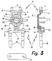
- This first assembly unit 1 essentially consists of a round plate 2, which - see FIG. 3 - serves as a receptacle or support for a toroidal core choke.
- the round plate 2 has two resilient hook elements 3 arranged diametrically to one another and projecting from the plane of the plate 2.
- a projecting web 4 adjoins the circumference, which in turn carries a cross web 5 at the end.
- This transverse web 5 is arranged transversely to the direction of the web 4 and has receiving bores for the contact sleeves 6 to be used in production.
- a block 7 which also projects outwards and has a particularly rectangular opening 8 at a distance from the round plate 2.
- the first assembly unit 1 described so far is manufactured as a separate molded part and is equipped as an individual part with the contact sleeves 6 and connected, in particular crimped, to the cable wires of the connecting cable.
- FIG. 2 shows the second assembly unit 10, the essential component of which is a rigid, approximately slot-shaped (see FIG. 3) connector bridge 11 with molded connector pins 12.
- the connector pins 12 are molded as is known so that they protrude on both sides of the plug bridge 11 - on the one hand, the plug pins that can be inserted into a power socket protrude and, on the other hand, these plug pins protrude from the back of the plug bridge 11 and offer a hollow cylindrical receptacle 12 'for the connecting wires the toroidal choke (see Fig. 3).
- the plug bridge 11 additionally has a bridge-like projection 13 centrally between the latter hollow cylindrical receptacles 12 '.
- This projection 13 extends approximately to half the connector bridge width and merges into a nose-like extension 14 at a distance from the connector bridge 11, the cross section of which is designed and dimensioned to be complementary to the opening (8 in FIG. 1) in the block (7 in FIG. 1) .
- FIG. 3 shows the mounting 20 consisting of the assembled mounting units 1 and 10 and completed in three views.
- the bracket 20 is first assembled in that the first assembly unit 1 with its opening 8 is plugged onto the complementary nose-like extension 14 of the second assembly unit 10. This gives a positive connection between these two assembly units 1 and 10 and a one-piece assembly body for final assembly and final production.
- This completion now consists in that a toroidal core choke 21 with its two coils 22, 23 is placed over the hook elements 3 of the first assembly unit 1 and is thus placed on the round plate 2.
- the connecting wire pairs 24/25, 26/27 projecting from the coils 22, 23 are then connected, in particular crimped, to the corresponding contact sleeves 6 or hollow cylindrical receptacles 12 'of the connector pins 12.
- the holder 20 thus completed is then finally placed in an injection mold and overmolded with plastic - the product is then a plug with two plug pins for insertion into a mains socket and a connecting cable (connected to the contact sleeves).
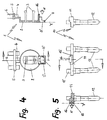
- FIGS. 4 and 5 A second exemplary embodiment of the assembly units 1 and 10 will be explained with reference to FIGS. 4 and 5. Relative to the (first) embodiment of the holder according to the invention shown in FIGS. 1 to 3, the difference and advantage is that the holder according to the second embodiment - Viewed axially - builds shorter because the projection of the second mounting unit 10 is integrated in the region of the plug bridge 11. This has the advantage that material can be saved overall.
- FIG. 4 shows - in analogy to FIG. 1 - a first assembly unit 1 with a round plate 2 for receiving a toroidal core choke between the resilient hook elements 3.
- the round plate 2 cries on one side the projecting web 4 with the cross web 5 and the contact sleeves 6 on.
- a protruding projection or block 7 ' is provided in the same way as in the exemplary embodiment according to FIG. 1, which also comprises a rectangular opening 8'.
- the extension 7 ' is stepped towards the outside, so that only a narrow web 9 remains as the outer boundary of the opening 8'.
- the connector bridge 11 lies against this narrow web 9 laterally.
- the second assembly unit 10 is provided on the inner peripheral bead of the opening 8 'protruding nose 16.
- Fig. 5 shows - in analogy to Fig. 2 - a second assembly unit 10. It consists of the connector bridge 11 with the molded connector pins 12 which protrude from the rear to the connector bridge 11 and provide a hollow cylindrical receptacle 12 'for the connecting wires of the toroidal choke.
- the complement to the opening 8 'or the approach 7' of the first assembly unit 1 is not formed as a projection (13 in Fig. 2), but as a laterally incorporated into the connector bridge 11 groove 15, the to the top with the contact sleeves 12 'is open. This results in a groove 15 which is open at the top on two sides and onto which the first assembly unit 1 with the web 9 and the adjacent sides can be attached. Through the groove 15, a projection 16 is formed, which engages positively during assembly in the opening 8 '.
- the two assembly units 1 and 10 explained with reference to FIGS. 4 and 5 are each manufactured individually. During assembly, both assembly units 1 and 10 are joined to one another or plugged onto one another (see arrow x) in such a way that the second assembly unit 10 in the region of the groove 15 and the projection 16 into the opening 8 'and on the narrow web 9 of the first assembly unit 1 is pushed. The plug bridge 11 then closes laterally with the base plane of the round plate 2 (cf. Y).
Landscapes
- Engineering & Computer Science (AREA)
- Power Engineering (AREA)
- Details Of Connecting Devices For Male And Female Coupling (AREA)
- Connector Housings Or Holding Contact Members (AREA)
Description
Die vorliegende Erfindung bezieht sich auf eine Halterung für eine im Steckerkörper eines elektrischen Netzsteckers integrierte Ringkerndrossel nach dem Oberbegriff des Patentanspruchs 1.The present invention relates to a holder for a toroidal inductor integrated in the plug body of an electrical mains plug according to the preamble of
Ein Netzstecker mit einer integrierten Halterung beziehungsweise Aufnahme für die stromkompensierte Ringkerndrossel ist in Verbindung mit einem sogenannten Zentralstecker aus der DE-OS 34 40 573 bekannt. Die Halterung beziehungsweise Aufnahme für die Ringkerndrossel ist dabei zusammen mit dem Quersteg und der Steckerbrücke als einstückiges Spritzteil ausgeführt, wobei gleichzeitig mit dem Spritzen der Steckerbrückenform die Steckerstifte eingelegt und fixiert werden. Das Einführen der Kontakthülsen, das Einlegen der Ringkerndrossel und das Verbinden der Anschlußdrähte der Ringkerndrossel mit den Kontakthülsen beziehungsweise den Steckerstiften erfolgt dann jeweils in aufeinanderfolgenden Arbeitsgängen. Dabei hat es sich gezeigt, daß aufgrund der Einstückigkeit der Grundmontageeinheit bestimmte Arbeitsgänge nicht so effizient ausgeführt werden können, wie dies aufgrund des auszuführenden Vorgangs an sich eigentlich möglich wäre. So ist beispielsweise das Einführen der Kontakthülsen vom Innenraum des Spritzteils her relativ zeitaufwendig, da die Innenkonturen, insbesondere die Steckerbrücke dem ungehinderten Zugang zum Quersteg erschweren.A power plug with an integrated holder or receptacle for the current-compensated toroidal choke is known in connection with a so-called central plug from DE-OS 34 40 573. The holder or receptacle for the toroidal core choke is designed together with the crossbar and the connector bridge as a one-piece molded part, the connector pins being inserted and fixed simultaneously with the injection molding of the connector bridge shape. The insertion of the contact sleeves, the insertion of the toroidal choke and the connection of the connecting wires of the toroidal core choke to the contact sleeves or the plug pins are then carried out in successive operations. It has been shown that, due to the one-piece design of the basic assembly unit, certain work steps cannot be carried out as efficiently as would actually be possible due to the process to be carried out. For example, inserting the contact sleeves from the interior of the molded part is relatively time-consuming, since the inner contours, in particular the connector bridge, make unhindered access to the crossbar more difficult.
Die der vorliegenden Erfindung zugrunde liegende Aufgabe besteht nun darin, eine Halterung der gattungsgemäßen Art anzugeben, mit der die Herstellung insoweit optimiert und maximiert werden kann, als die einzelnen Arbeitsgänge zur Fertigstellung der aus Quersteg, Halterung und Steckerbrücke bestehenden Grundeinheit für den Steckerkörper jeweils optimal je für sich ausgeführt werden können.The object underlying the present invention is now to provide a holder of the generic type with which the production can be optimized and maximized insofar as the individual operations for the completion of the basic unit consisting of crossbar, holder and plug bridge for the plug body each optimally can be done for yourself.
Die Lösung der vorgenannten Aufgabe besteht darin, daß der Quersteg mit den Kontakthülsen und den Kabeladerenden, sowie die Halterung mit der Ringkerndrossel einerseits und die Steckerbrücke mit den Steckerstiften andererseits je eine separate Montageeinheit bilden, die vor dem Umspritzen mit Kunststoff formschlüssig zusammengefügt werden.The solution to the above problem is that the crossbar with the contact sleeves and the cable wire ends, as well as the bracket with the toroidal core choke on the one hand and the connector bridge with the connector pins on the other, each form a separate assembly unit which are joined together in a form-fitting manner before the encapsulation with plastic.
Damit ist es nun möglich, daß die beiden Montageeinheiten jeweils für sich soweit vorbereitet und fertiggestellt werden, daß erst mit dem Zusammenfügen die Halterung entsteht, in die dann die Ringkerndrossel eingelegt beziehungsweise eingeklipst und bezüglich ihrer Anschlußdrähte mit den Kontakthülsen und den Steckerstiften verbunden, insbesondere verquetscht (gecrimpt) wird.It is now possible that the two assembly units are each prepared and completed for themselves so that the holder is only created when the two are assembled, into which the toroidal inductor is then inserted or clipped and connected, in particular squeezed, with respect to their connecting wires to the contact sleeves and the plug pins (crimped).
Besondere Ausgestaltungen im Hinblick auf die erfindungsgemäße Konzeption sind Gegenstand der Unteransprüche, wobei in den Ansprüchen 3 und 4 die besonderen Merkmale zweier Ausführungsvarianten spezifiziert sind. Die Erfindung wird im folgenden anhand der Zeichnung näher erläutert. Diese zeigt in
- Fig. 1
- - und zwar in zwei teilweise geschnittenen Ansichten - ein erstes Ausführungsbeispiel einer aus einer Halterung für die Ringkerndrossel und einem Quersteg für die Kontakthülsen bestehenden erste Montageeinheit;
- Fig. 2
- - und zwar in drei teilweise geschnittenen Ansichten - eine die Steckerbrücke mit den Steckerstiften enthaltende zur Montageeinheit nach Fig. 1 komplementäre zweite Montageeinheit;
- Fig. 3
- - in drei teilweise geschnittenen Ansichten - ein erstes Ausführungsbeispiel einer aus den Montageeinheiten nach Fig. 1 und Fig. 2 zusammengefügten Halterung (vor dem Umspritzen mit Kunststoff);
- Fig. 4
- - und zwar in zwei teilweise geschnittenen Ansichten - ein zweites Ausführungsbeispiel einer aus einer Halterung für die Ringkerndrossel und einem Quersteg für die Kontakthülsen bestehenden erste Montageeinheit;
- Fig. 5
- - und zwar in drei teilweise geschnittenen Ansichten - eine die Steckerbrücke mit den Steckerstiften enthaltende zur Montageeinheit nach Fig. 4 komplementäre zweite Montageeinheit.
- Fig. 1
- - namely in two partially sectioned views - a first embodiment of a first assembly unit consisting of a holder for the toroidal core choke and a crossbar for the contact sleeves;
- Fig. 2
- - in three partially sectioned views - a second assembly unit, which contains the connector bridge with the connector pins and is complementary to the assembly unit according to FIG. 1;
- Fig. 3
- - In three partially sectioned views - a first embodiment of a bracket assembled from the assembly units according to FIGS. 1 and 2 (before overmolding with plastic);
- Fig. 4
- - namely in two partially sectioned views - a second embodiment of a first assembly unit consisting of a holder for the toroidal choke and a crossbar for the contact sleeves;
- Fig. 5
- - in three partially sectioned views - a second assembly unit which contains the connector bridge with the connector pins and is complementary to the assembly unit according to FIG. 4.
Fig. 1 zeigt die erste Montageeinheit 1 der erfindungsgemäßen Halterung. Diese erste Montageeinheit 1 besteht im wesentlichen aus einer runden Platte 2, die - vergleiche Fig. 3 - als Aufnahme beziehungsweise Auflage für eine Ringkerndrossel dient. Zur Arretierung beziehungsweise Fixierung dieser Ringkerndrossel weist die runde Platte 2 zwei diametral zueinander angeordnete, der Ebene der Platte 2 gegenüber abstehende federnde Hakenelemente 3 auf.1 shows the
An der runden Platte 2 selbst schließt umfangsseitig ein abstehender Steg 4 an, der endseitig seinerseits einen Quersteg 5 trägt. Dieser Quersteg 5 ist quer zur Richtung des Stegs 4 angeordnet und weist Aufnahmebohrungen für die bei der Fertigung einzusetzenden Kontakthülsen 6 auf.On the
Diametral zum Steg 4 ist ein ebenfalls nach außen abstehender Kloben 7 angesetzt, der im Abstand zur runden Platte 2 einen insbesondere rechteckigen Durchbruch 8 aufweist.Diametrically to the
Die soweit beschriebene erste Montageeinheit 1 ist als separates Spritzteil gefertigt und wird für sich als Einzelteil mit den Kontakthülsen 6 bestückt und mit den Kabeladern des Anschlußkabels verbunden, insbesondere vercrimpt.The
Fig. 2 zeigt die zweite Montageeinheit 10, deren wesentlicher Bestandteil eine steife, etwa langlochförmige (vergleiche Fig. 3) Steckerbrücke 11 mit angegossenen Steckerstiften 12 ist. Die Steckerstifte 12 sind wie an sich bekannt so angespritzt, daß sie an beiden Seiten der Steckerbrücke 11 abstehen - einerseits stehen die in einer Netzsteckdose einführbaren Steckerstifte ab und andererseits stehen diese Steckerstifte rückseitig zur Steckerbrücke 11 über und bieten eine hohlzylindrische Aufnahme 12′ für die Anschlußdrähte der Ringkerndrossel (vergleiche Fig. 3).FIG. 2 shows the
Der vorliegenden Erfindung gemäß weist die Steckerbrücke 11 zusätzlich und zwar mittig zwischen den zuletzt genannten hohlzylindrischen Aufnahmen 12′ einen brückenartigen Vorsprung 13 auf. Dieser Vorsprung 13 reicht etwa bis zur Hälfte der Steckerbrückenbreite und geht im Abstand zur Steckerbrücke 11 in einen nasenartigen Ansatz 14 über, dessen Querschnitt dem Durchbruch (8 in Fig. 1) im Kloben (7 in Fig. 1) entsprechend komplementär ausgebildet und dimensioniert ist.According to the present invention, the
Diese beiden anhand von Fig. 1 und Fig. 2 erläuterten Montageeinheiten 1 beziehungsweise 10 werden je für sich gefertigt und soweit vorbereitet, daß sie quasi nur für die Endmontage zusammengefügt zu werden brauchen.These two
Fig. 3 zeigt die aus den zusammengefügten Montageeinheiten 1 und 10 bestehende und komplettierte Halterung 20 in drei Ansichten.FIG. 3 shows the mounting 20 consisting of the assembled
Die Halterung 20 wird zunächst dadurch montiert, daß die erste Montageeinheit 1 mit ihrem Durchbruch 8 auf den komplementären nasenartigen Ansatz 14 der zweiten Montageeinheit 10 aufgesteckt wird. Damit erhält man eine formschlüssige Verbindung zwischen diesen beiden Montageeinheiten 1 beziehungsweise 10 und einen einstückigen Montagekörper für die Endmontage und Endfertigung.The bracket 20 is first assembled in that the
Diese Endfertigung besteht nun darin, daß eine Ringkerndrossel 21 mit ihren beiden Spulen 22, 23 über die Hakenelemente 3 der ersten Montageeinheit 1 gesteckt und so auf die runde Platte 2 aufgelegt wird. Die von den Spulen 22, 23 abstehenden Anschlußdrahtpaare 24/25, 26/27 werden sodann mit den entpsrechenden Kontakthülsen 6 beziehungsweise hohlzylindrischen Aufnahmen 12′ der Steckerstifte 12 verbunden, insbesondere vercrimpt. Die so komplettierte Halterung 20 wird dann letztendlich in eine Spritzform eingelegt und mit Kunststoff umspritzt - das Produkt ist dann ein Stecker mit zwei Steckerstiften zum Einführen in eine Netzsteckdose und einem (mit den Kontakthülsen verbundenen) Anschlußkabel.This completion now consists in that a
Anhand der Fig. 4 und Fig. 5 soll ein zweites Ausführungsbeispiel der Montageeinheiten 1 bzw. 10 erläutert werden. Relativ zu dem anhand der Fig. 1 bis 3 dargestellten (ersten) Ausführungsbeispiel der erfindungsgemäßen Halterung besteht der Unterschied und Vorteil darin, daß die Halterung gemäß dem zweiten Ausführungsbeispiel - axial betrachtet - kürzer baut, weil der Vorsprung der zweiten Montageeinheit 10 in den Bereich der Steckerbrücke 11 integriert ist. Dies hat noch den Vorteil, daß insgesamt betrachtet Material eingespart werden kann.A second exemplary embodiment of the
Fig. 4 zeigt - in Analogie zu Fig. 1 - eine erste Montageeinheit 1 mit einer runden Platte 2 für die Aufnahme einer Ringkerndrossel zwischen den federnden Hakenelementen 3. Die runde Platte 2 weint einseitig den abstehenden Steg 4 mit dem Quersteg 5 und den Kontakthülsen 6 auf.FIG. 4 shows - in analogy to FIG. 1 - a
An der diametralen Seite der runden Platte 2 ist gleichermaßen wie beim Ausführungsbeispiel nach Fig. 1 ein abstehender Ansatz bzw. Kloben 7′ vorgesehen, der ebenfalls einen rechteckigen Durchbruch 8′ umfaßt. Anders als bei der ersten Montageeinheit 1 nach Fig. 1 ist der Ansatz 7′ zur Außenseite hin abgestuft, so daß nur ein schmaler Steg 9 als Außenbegrenzung des Durchbruchs 8′ verbleibt. An diesen schmalen Steg 9 legt sich bei der Montage der beiden Montageeinheiten 1 und 10 die Steckerbrücke 11 seitlich an. Zur zusätzlichen Abstützung der zweiten Montageeinheit 10 ist noch eine an der inneren Umfangswulst des Durchbruchs 8′ vorstehende Nase 16 vorgesehen.On the diametrical side of the
Fig. 5 zeigt - in Analogie zu Fig. 2 - eine zweite Montageeinheit 10. Sie besteht aus der Steckerbrücke 11 mit den angegossenen Steckerstiften 12, die rückseitig zur Steckerbrücke 11 überstehen und eine hohlzylindrische Aufnahme 12′ für die Anschlußdrähte der Ringkerndrossel bieten.Fig. 5 shows - in analogy to Fig. 2 - a
In Abänderung zum Ausführungsbeispiel nach Fig. 2 ist die zum Durchbruch 8′ bzw. zum Ansatz 7′ der ersten Montageeinheit 1 komplementäre Rast nicht als Vorsprung (13 in Fig. 2) ausgebildet, sondern als seitlich in die Steckerbrücke 11 eingearbeitete Nut 15, die zu der mit den Kontakthülsen 12′ bestückten Oberseite hin offen ist. Damit ergibt sich eine auf zwei Seiten nach oben offene Nut 15 , an die die erste Montageeinheit 1 mit dem Steg 9 und den angrenzenden Seiten aufgesteckt werden kann. Durch die Nut 15 bildet sich ein Vorsprung 16, der bei der Montage in den Durchbruch 8′ formschlüssig eingreift.2, the complement to the opening 8 'or the approach 7' of the
Die beiden anhand von Fig. 4 und Fig. 5 erläuterten Montageeinheiten 1 bzw. 10 sind je für sich gefertigt. Bei der Montage werden beide Montageeinheiten 1 und 10 so aneinandergefügt bzw. aufeinander gesteckt (vgl. Pfeilx), daß die zweite Montageeinheit 10 im Bereich der Nut 15 und des Vorsprungs 16 in den Durchbruch 8′ und auf den schmalen Steg 9 der ersten Montageeinheit 1 geschoben wird. Die Steckerbrücke 11 schließt dann seitlich mit der Grundebene der runden Platte 2 ab (vgl . Y).The two
Claims (5)
- A mounting for a current-compensated toroidal core throttle (21) serving to provide electrical appliances with supply-interference immunity and integrated in the plug body of an electrical mains plug the mounting of which is connected on one side to two contact tubes (6), fixed mechanically by means of a crossbar (5), to hold the leads of an electrical connecting cable, and on the other side to two plug pins (12) fixed at the standard distance apart by means of a plug bridge (11),
wherein the unit consisting of the crossbar with the contact tubes and the ends of the cable leads, the mounting (23) with the toroidal core throttle and the plug bridge has plastic injection-mould around it and forms a grip body from which the plug pins designed for being inserted into a socket of a power supply system, project on one side and from which, on the other side, the connecting cable goes out,
characterized in that
the crossbar (5) with the contact tubes (6) and the ends of the cable leads as well as the mounting (2) with the toroidal core throttle (21) on the one side and the plug bridge (11) with the plug pins (12) on the other side form one separate assembly unit (1, 10) each which are coupled to each other in a form-fit way prior to injection moulding. - Mounting according to claim 1
characterized in that
the assembly units (1,10) have locking means which are complementary to each other, by means of which they can be plugged together. - Mounting according to claim 1 or 2
characterized in that
one of the assembly units (1,10) is fitted with a lug oriented towards the other assembly unit and provided with an opening (8) and the other assembly unit has a conjugated lug (13) provided with a projecting piece (14) complementary to the opening (8). - Mounting according to claim 1 or 2
characterized in that
one of the assembly units (1) is provided with a lug (7′) with an opening (10) projecting from the side diametral to the crossbar (5) and that the other assembly unit (10) has a nut (15) which is incorporated in the area of a plug bridge side and open towards the front side of the plug bridge (11) that is fitted with the contact tubes (12′),
so that this other assembly unit (10) with the opening (8′) can be plugged onto the first assembly unit (1) via the nut (15). - Mounting according to claim 4
characterized in that,
in the area of the mounting (2) for the toroidal core throttle (21), the lug (7′) is provided with a projection (16) which, when the assembly unit (1,10) is mounted, is put against the upper side of the plug bridge (11).
Applications Claiming Priority (4)
| Application Number | Priority Date | Filing Date | Title |
|---|---|---|---|
| DE4107302 | 1991-03-07 | ||
| DE4107302 | 1991-03-07 | ||
| DE4114036 | 1991-04-29 | ||
| DE4114036A DE4114036A1 (en) | 1991-03-07 | 1991-04-29 | BRACKET FOR A RING CORE THROTTLE OF AN ELECTRICAL POWER PLUG |
Publications (2)
| Publication Number | Publication Date |
|---|---|
| EP0502467A1 EP0502467A1 (en) | 1992-09-09 |
| EP0502467B1 true EP0502467B1 (en) | 1994-10-12 |
Family
ID=25901654
Family Applications (1)
| Application Number | Title | Priority Date | Filing Date |
|---|---|---|---|
| EP92103597A Expired - Lifetime EP0502467B1 (en) | 1991-03-07 | 1992-03-02 | Holding device for toroidal core throttle of a main plug |
Country Status (2)
| Country | Link |
|---|---|
| EP (1) | EP0502467B1 (en) |
| DE (2) | DE4114036A1 (en) |
Families Citing this family (8)
| Publication number | Priority date | Publication date | Assignee | Title |
|---|---|---|---|---|
| DE4239818C2 (en) * | 1992-11-26 | 2001-11-29 | Epcos Ag | Coiled toroid |
| DE4402351C2 (en) * | 1994-01-27 | 1999-01-07 | Hans M Strassner | Device for suppressing hum and interfering interference on audio connecting lines |
| ES2102940B1 (en) * | 1994-04-13 | 1998-04-01 | Cablerias Conductoras Sa | ELECTRICAL CONNECTION DEVICE BY PLUG. |
| US6198643B1 (en) * | 1998-11-20 | 2001-03-06 | Audio Line Source, Llc | System with choke in parallel with A/C power line for load conditioning |
| DE29821736U1 (en) * | 1998-12-07 | 2000-04-13 | Robert Bosch Gmbh, 70469 Stuttgart | Hand tool |
| DE202004014066U1 (en) | 2004-09-09 | 2004-12-16 | Vogt Electronic Aktiengesellschaft | Carrier component and suppression choke device |
| DE102010031292B4 (en) * | 2010-07-13 | 2020-06-18 | Würth Elektronik eiSos Gmbh & Co. KG | Holder for a coil |
| DE102012107902A1 (en) * | 2012-08-28 | 2014-03-06 | Lapp Engineering & Co. | Plug unit and electrical device with such a plug unit |
Citations (1)
| Publication number | Priority date | Publication date | Assignee | Title |
|---|---|---|---|---|
| EP0468314A1 (en) * | 1990-07-27 | 1992-01-29 | Taller GmbH | Holding device for toroidal core throttle integrated in an electrical main plug housing |
Family Cites Families (5)
| Publication number | Priority date | Publication date | Assignee | Title |
|---|---|---|---|---|
| DE7623595U1 (en) * | 1976-07-27 | 1978-03-09 | Karl Stolle, Kabel- Und Antennenfabrik, 4670 Luenen | Transformer plug |
| EP0090774B1 (en) * | 1982-03-26 | 1989-03-01 | Feller Ag | Device for protecting an electrical apparatus against disturbances |
| DE3440573A1 (en) * | 1984-11-07 | 1986-05-07 | Vogt electronic AG, 8391 Erlau | ELECTRIC COMPENSATED THROTTLE IN A EUROSTECKER |
| DE3842038A1 (en) * | 1988-12-14 | 1990-06-21 | Vogt Electronic Ag | Plug link for European-standard plugs having an integrated inlet inductor |
| DE3922398A1 (en) * | 1989-07-07 | 1991-01-17 | Vogt Electronic Ag | Connected cable with integrated inductance - fitted in mains supply plug for suppression of interference to appts. connected telecommunications |
-
1991
- 1991-04-29 DE DE4114036A patent/DE4114036A1/en active Granted
-
1992
- 1992-03-02 EP EP92103597A patent/EP0502467B1/en not_active Expired - Lifetime
- 1992-03-02 DE DE59200610T patent/DE59200610D1/en not_active Expired - Fee Related
Patent Citations (1)
| Publication number | Priority date | Publication date | Assignee | Title |
|---|---|---|---|---|
| EP0468314A1 (en) * | 1990-07-27 | 1992-01-29 | Taller GmbH | Holding device for toroidal core throttle integrated in an electrical main plug housing |
Also Published As
| Publication number | Publication date |
|---|---|
| EP0502467A1 (en) | 1992-09-09 |
| DE59200610D1 (en) | 1994-11-17 |
| DE4114036A1 (en) | 1992-09-10 |
| DE4114036C2 (en) | 1993-02-18 |
Similar Documents
| Publication | Publication Date | Title |
|---|---|---|
| CH622870A5 (en) | ||
| DE3145816C2 (en) | Electrical plug | |
| EP0502467B1 (en) | Holding device for toroidal core throttle of a main plug | |
| EP0332034B1 (en) | Bridging means for safety plug with hollow cylindrical pins for the current and earth leads | |
| EP0907928B1 (en) | Leadframe for the assembly of an integrated circuit in an injection mounded housing | |
| EP0930672B1 (en) | Bridge for holding pins for an electric mains plug with build-in fuse | |
| DE19632870C2 (en) | Connector housing | |
| EP0468314B1 (en) | Holding device for toroidal core throttle integrated in an electrical main plug housing | |
| EP0274605B1 (en) | Plug with protective contact provided with pin supporting bridge and protection cap | |
| EP0625806B1 (en) | Appliance connector with a moulded component and with a holding plate for contact springs | |
| DE4012581C2 (en) | Earthing contact plug with a bridge-like molded part | |
| EP1841020A2 (en) | Pin protection | |
| DE4200301C1 (en) | ||
| EP1128497B1 (en) | Process for manufacturing a switching device base | |
| EP0373498A2 (en) | Plug socket for a multipole plug connection for the electrical link-up of a motor vehicle trailer | |
| DE2903954C2 (en) | Connector housing | |
| DE4321872A1 (en) | Holder for an annular core inductor (toroidal core inductor) | |
| EP0521190A1 (en) | Plug bridge for a protective contact plug of an electric apparatus | |
| EP0391298A2 (en) | Connector with protective contact and with a lead-in help coordinated to the connection socket of the protective contact | |
| DE4012582C2 (en) | Earthing contact plug with an integrated T-shaped molding | |
| DE10010339A1 (en) | Plug bridge has base plate extended to second geometric shape and extension area has at least one passage hole suitable for penetration by contact pin in non-standard arrangement | |
| DE3516976A1 (en) | Method for producing an electrical pot-cored coil, a winding mandrel for carrying out the method, and a pot-cored coil | |
| DE8912173U1 (en) | Filter plug | |
| EP0452761A1 (en) | Protective contact plug with base plate and earth spring contact | |
| DE29718682U1 (en) | Electrical connector |
Legal Events
| Date | Code | Title | Description |
|---|---|---|---|
| PUAI | Public reference made under article 153(3) epc to a published international application that has entered the european phase |
Free format text: ORIGINAL CODE: 0009012 |
|
| AK | Designated contracting states |
Kind code of ref document: A1 Designated state(s): DE ES FR IT |
|
| 17P | Request for examination filed |
Effective date: 19920826 |
|
| 17Q | First examination report despatched |
Effective date: 19940328 |
|
| GRAA | (expected) grant |
Free format text: ORIGINAL CODE: 0009210 |
|
| AK | Designated contracting states |
Kind code of ref document: B1 Designated state(s): DE ES FR IT |
|
| PG25 | Lapsed in a contracting state [announced via postgrant information from national office to epo] |
Ref country code: FR Effective date: 19941012 Ref country code: ES Free format text: THE PATENT HAS BEEN ANNULLED BY A DECISION OF A NATIONAL AUTHORITY Effective date: 19941012 |
|
| ITF | It: translation for a ep patent filed | ||
| REF | Corresponds to: |
Ref document number: 59200610 Country of ref document: DE Date of ref document: 19941117 |
|
| EN | Fr: translation not filed | ||
| PLBI | Opposition filed |
Free format text: ORIGINAL CODE: 0009260 |
|
| 26 | Opposition filed |
Opponent name: VOGT ELECTRONIC AG Effective date: 19950712 |
|
| PLBM | Termination of opposition procedure: date of legal effect published |
Free format text: ORIGINAL CODE: 0009276 |
|
| STAA | Information on the status of an ep patent application or granted ep patent |
Free format text: STATUS: OPPOSITION PROCEDURE CLOSED |
|
| 27C | Opposition proceedings terminated |
Effective date: 19951130 |
|
| PGFP | Annual fee paid to national office [announced via postgrant information from national office to epo] |
Ref country code: DE Payment date: 20050324 Year of fee payment: 14 |
|
| PGFP | Annual fee paid to national office [announced via postgrant information from national office to epo] |
Ref country code: IT Payment date: 20060331 Year of fee payment: 15 |
|
| PG25 | Lapsed in a contracting state [announced via postgrant information from national office to epo] |
Ref country code: DE Free format text: LAPSE BECAUSE OF NON-PAYMENT OF DUE FEES Effective date: 20061003 |
|
| PG25 | Lapsed in a contracting state [announced via postgrant information from national office to epo] |
Ref country code: IT Free format text: LAPSE BECAUSE OF NON-PAYMENT OF DUE FEES Effective date: 20070302 |