EP0502355B1 - Messerwellen-Abstreifvorrichtung für Schriftgutvernichter - Google Patents
Messerwellen-Abstreifvorrichtung für Schriftgutvernichter Download PDFInfo
- Publication number
- EP0502355B1 EP0502355B1 EP92102655A EP92102655A EP0502355B1 EP 0502355 B1 EP0502355 B1 EP 0502355B1 EP 92102655 A EP92102655 A EP 92102655A EP 92102655 A EP92102655 A EP 92102655A EP 0502355 B1 EP0502355 B1 EP 0502355B1
- Authority
- EP
- European Patent Office
- Prior art keywords
- cutter
- webs
- stripping
- block
- roller
- Prior art date
- Legal status (The legal status is an assumption and is not a legal conclusion. Google has not performed a legal analysis and makes no representation as to the accuracy of the status listed.)
- Expired - Lifetime
Links
Images


Classifications
-
- B—PERFORMING OPERATIONS; TRANSPORTING
- B02—CRUSHING, PULVERISING, OR DISINTEGRATING; PREPARATORY TREATMENT OF GRAIN FOR MILLING
- B02C—CRUSHING, PULVERISING, OR DISINTEGRATING IN GENERAL; MILLING GRAIN
- B02C18/00—Disintegrating by knives or other cutting or tearing members which chop material into fragments
- B02C18/0007—Disintegrating by knives or other cutting or tearing members which chop material into fragments specially adapted for disintegrating documents
- B02C2018/0069—Disintegrating by knives or other cutting or tearing members which chop material into fragments specially adapted for disintegrating documents with stripping devices
Definitions
- the invention relates to a knife shaft stripping device for document shredders, whose one-piece stripping webs are arranged in the cutting unit in the cutting zone between the knives of the knife shafts.
- the invention has for its object to simplify the structure of a document shredder and to reduce the number of items and the required assembly and adjustment.
- the invention has the characterizing features of claim 1.
- the fact that the stripping webs are produced as a stripping block which can be fastened in a receptacle of a housing part of the document shredder achieves a simplified construction of the device. The cost of manufacturing the individual parts can be reduced.
- the arrangement of the scraper block with the scraper bars obtains the required stability by assigning support bars to the scraper bars, which are arranged on the opposite housing part.
- the scraper webs and the support webs are provided with support surfaces which lie one on top of the other in the assembled state of the cutting mechanism, such that the scraper webs are supported and the scraper block is fixed in its position.
- the receptacle for the stripping block is trough-shaped and the stripping block is arranged in the receptacle with play ensures that certain manufacturing tolerances of the knife shafts can be compensated for automatically.
- the scraper block positions itself automatically when the cutting unit is installed according to the position of the knives of the knife shafts.
- the stripping block as a molded part, in particular as a plastic molded part.
- Scraper webs molded from plastic also have the required stability due to the design described.
- the support webs are injection-molded in one piece with a plastic housing part.
- a further simplification of the structure of the cutting mechanism can be achieved.
- the receptacle for the stripping block is preferably arranged on the lower housing part of the document shredder, while the support webs are arranged on the upper housing part.
- the support surfaces of the scraper webs and the support webs are then above the cutting zone of the cutting unit in the area of the paper feed, so that any edges in the area of the support surfaces can in no way negatively influence the function of the scraper webs. This preferred solution reliably rules out a jam of shredded paper particles in the cutting unit.
- bearing surfaces for the knife shafts are also injected into the lower housing part or into the upper housing part in addition to the receptacle for the stripping block and the supporting webs, the construction and in particular also the assembly of the cutting mechanism can be further simplified considerably. This also applies in particular if the receptacle for a drive motor and bearing surfaces for a transmission are also injected. All of the essential components of the cutting unit are then correctly positioned in relation to one another without an adjustment having to be made. As already stated, manufacturing tolerances of the knife shaft can, if necessary, be compensated for by arranging the stripping block with the stripping bars in its receptacle with play.
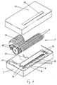
- 1 denotes a cutting device of a document shredder.
- the cutting unit 1 has two knife shafts 2, on which, in a manner known per se, interlocking knives 3 are arranged for comminuting the writing material not shown in the drawing.
- a knife shaft stripping device consisting of two rows of stripping webs 4 and associated supporting webs 5 is arranged on the two knife shafts 2.
- the stripping webs 4 are combined to form a stripping block 6.
- the stripping webs 4 engage in the spaces between the knives 3 of the knife shafts 2 and fill them. This prevents shredded documents from entering these gaps.
- the stripping webs 4 are comb-shaped and molded in one piece from plastic to form a stripping block 6.
- a trough-shaped receptacle 8 is arranged on the lower housing part 7 for the stripping block 6.
- the stripping block 6 is held in the receptacle 8 in the assembled state of the cutting unit 1.
- the stripping block 6 is preferably arranged with play in this receptacle 8, so that then manufacturing tolerances of the knife shaft 2 are automatically compensated.
- the support webs 5 have on their upper end face support surfaces 9 which are arranged at an angle to one another.
- Corresponding support surfaces 10 are arranged on the end faces of the scraper webs 4. In the assembled state of the cutting unit 1, d. H. When the upper housing part 11 is placed on the lower housing part 7, the support surfaces 9 and 10 lie one on top of the other.
- the support surfaces 10 of the support webs 5 engage in the support surfaces 9 of the wiper webs in such a way that the wiper webs 4 are supported both laterally and in the vertical direction.
- the stability of the cutting mechanism 1 is further increased by reinforcing ribs 12 arranged on the receptacle 8.
- the interlocking of the stripping webs 4 and the supporting webs 5 also increases the overall stability of the document shredder housing consisting of the lower housing part 7 and the upper housing part 11 in an advantageous manner.
- a paper inlet shaft 13 is arranged in the upper housing part 11 for feeding the paper to be shredded.
- bearing surfaces 14 for the knife shafts 2 are arranged in the lower housing part 7 and in the upper housing part 11. These bearing surfaces 14, like the receptacle 8 for the stripping block 6 and the supporting webs 5, are injected into the lower housing part 7 and into the upper housing part 11.
- bearing surfaces 17 for a gear 18 are also injected into the upper housing part 11 and the lower housing part 7.
- the drive motor 16 drives the knife shafts 2 of the cutting mechanism 1 via the gear 18.
- the paper For shredding, the paper, not shown in the drawing, is introduced into the paper inlet shaft 13 and then reaches the knives 3 of the knife shafts 2. The overlapping knives 3 shred the paper, the stripping webs 4 preventing the paper from entering the spaces between the knives 3 occurs. The shredded paper then passes through a paper channel 19 formed between the stripping bars 4 and supporting bars 5 arranged on both sides into a collecting container, not shown in the drawing.
- the scraper webs 4 are supported by the support webs 5, despite their preferred design as a flexible plastic part, they are precisely fixed in their position. As has surprisingly been shown, it is ensured on the basis of the design according to the invention that the stripping webs 4 remain in their position during the comminution process. Even under the action of the forces exerted by the paper to be shredded, there is no such deformation of the scraper webs 4 molded from plastic that malfunctions could occur.
- the design of the stripping webs 4 and the supporting webs 5 as a plastic injection molded part results in the advantage of a very inexpensive production.
- the individual parts of the document shredder are very easy to assemble in the inventive design.
- the stripper block 6 it is ultimately only necessary to insert the stripper block 6 into its receptacle 8, the knife shafts 2 into its bearing surfaces 14, the drive motor 16 into its receptacle 15, and the transmission 18 into the lower housing part 7 insert into its bearing surface 17. Then the upper housing part with the support webs 5 and the corresponding bearing surfaces is placed.
- the stripping block 6 is aligned and fixed automatically on the support surfaces 10 of the support webs 5 and on the knife shafts.
Landscapes
- Engineering & Computer Science (AREA)
- Food Science & Technology (AREA)
- Crushing And Pulverization Processes (AREA)
- Facsimile Heads (AREA)
- Electrochromic Elements, Electrophoresis, Or Variable Reflection Or Absorption Elements (AREA)
- Printers Or Recording Devices Using Electromagnetic And Radiation Means (AREA)
Applications Claiming Priority (2)
| Application Number | Priority Date | Filing Date | Title |
|---|---|---|---|
| DE4106792A DE4106792C1 (enExample) | 1991-03-04 | 1991-03-04 | |
| DE4106792 | 1991-03-04 |
Publications (2)
| Publication Number | Publication Date |
|---|---|
| EP0502355A1 EP0502355A1 (de) | 1992-09-09 |
| EP0502355B1 true EP0502355B1 (de) | 1995-06-28 |
Family
ID=6426392
Family Applications (1)
| Application Number | Title | Priority Date | Filing Date |
|---|---|---|---|
| EP92102655A Expired - Lifetime EP0502355B1 (de) | 1991-03-04 | 1992-02-15 | Messerwellen-Abstreifvorrichtung für Schriftgutvernichter |
Country Status (7)
| Country | Link |
|---|---|
| US (1) | US5400978A (enExample) |
| EP (1) | EP0502355B1 (enExample) |
| AT (1) | ATE124296T1 (enExample) |
| DE (2) | DE4106792C1 (enExample) |
| DK (1) | DK0502355T3 (enExample) |
| ES (1) | ES2075492T3 (enExample) |
| GR (1) | GR3017227T3 (enExample) |
Families Citing this family (24)
| Publication number | Priority date | Publication date | Assignee | Title |
|---|---|---|---|---|
| US5511732A (en) * | 1994-12-28 | 1996-04-30 | Fellowes Manufacturing Company | Document shredding machine with continuous stripper |
| US5829697A (en) | 1995-08-24 | 1998-11-03 | Fellowes Manufacturing Company | Support for cylinders in a paper shredder |
| DE19545087C2 (de) * | 1995-12-04 | 2003-06-12 | Hermann Schwelling | Klein-Aktenvernichter |
| CN2267860Y (zh) * | 1996-01-22 | 1997-11-19 | 至法实业有限公司 | 碎纸机 |
| DE19610048A1 (de) * | 1996-03-14 | 1997-09-18 | Schleicher & Co Int | Schriftgutvernichter |
| DE19758749B4 (de) * | 1997-03-26 | 2004-02-05 | Schleicher & Co International Ag | Schneidwerk eines Dokumentenvernichters |
| US5961059A (en) * | 1997-04-30 | 1999-10-05 | Fellowes Manufacturing Company | Support for drive system in a paper shredder |
| US5826809A (en) * | 1997-04-30 | 1998-10-27 | Fellowes Manufacturing Company | Support for cutting cylinders in a paper shredder |
| WO1999001223A2 (de) * | 1997-07-04 | 1999-01-14 | WILHELM DAHLE BüRO-TECHNIK GMBH & CO. KG | Dokumentenvernichter |
| US5954280A (en) * | 1998-05-12 | 1999-09-21 | Fellowes Manufacturing Company | Top blocker for a paper shredder |
| USD412716S (en) | 1998-06-30 | 1999-08-10 | Fellowes Manufacturing Company | Paper shredder |
| USD410246S (en) | 1998-09-15 | 1999-05-25 | General Binding Corporation | Paper shredder |
| US6241170B1 (en) * | 2000-01-21 | 2001-06-05 | Cd Systems Inc. | Industrial shredders and novel components therefor |
| USD444809S1 (en) | 2000-05-31 | 2001-07-10 | Frank Chang | Shredder |
| USD481416S1 (en) | 2003-03-11 | 2003-10-28 | Frank Chang | Shredder |
| US20100282885A1 (en) * | 2007-04-27 | 2010-11-11 | Jesus Perez Santafe | Grinding container for the selective collection of solid urban waste and various special adaptations for each type of waste, including a domestic grinding container |
| US7753295B1 (en) * | 2007-08-27 | 2010-07-13 | Emily Lo | Paper shredder which prevents cutting fingers |
| US7601052B1 (en) * | 2008-03-31 | 2009-10-13 | Key Systems, Inc. | Key destroyer |
| US20100176231A1 (en) * | 2009-01-14 | 2010-07-15 | Michilin Prosperity Co., Ltd. | Package-type break-preventing device for rotary shafts of a shredder |
| DE202009013428U1 (de) * | 2009-10-05 | 2011-03-03 | Schwelling, Hermann | Aktenvernichter mit Metallerkennung |
| US20130214072A1 (en) * | 2012-02-20 | 2013-08-22 | Tex Year Industries Inc. | Rotary cutter door device for paper shredders |
| WO2014113589A1 (en) * | 2013-01-17 | 2014-07-24 | Merit Medical Systems, Inc. | Apparatuses and kits for grinding or cutting surgical foam and methods related thereto |
| DE102014016920A1 (de) * | 2014-11-17 | 2016-05-19 | Giesecke & Devrient Gmbh | Vorrichtung zum Schreddern von Wertdokumenten |
| US10537896B2 (en) * | 2016-07-05 | 2020-01-21 | Aurora Office Equipment Co., Ltd. Shanghai | Autofeed paper shredder with clip and staple removal |
Family Cites Families (6)
| Publication number | Priority date | Publication date | Assignee | Title |
|---|---|---|---|---|
| US4018392A (en) * | 1975-12-22 | 1977-04-19 | Wagner John W | Shredding machine |
| EP0010681B1 (de) * | 1978-10-19 | 1982-04-14 | Günter Trautmann | Vorrichtung zum Zerschneiden oder Zerkleinern von Papier, Karton, Mikrofilmen od. dgl |
| GB2096919B (en) * | 1981-03-11 | 1984-12-05 | Matsushita Electric Industrial Co Ltd | Shredder |
| DE3616554C2 (de) * | 1986-05-16 | 1995-05-24 | Schleicher Co Feinwerktech | Messerwalzen-Abstreifvorrichtung für Aktenvernichter oder dgl. |
| DE4003222C1 (enExample) * | 1990-02-03 | 1991-04-18 | Pbs-Servicegesellschaft Mbh & Co. Kg, 3000 Hannover, De | |
| US5071080A (en) * | 1990-02-27 | 1991-12-10 | Fellowes Manufacturing Company | Document shredding machine |
-
1991
- 1991-03-04 DE DE4106792A patent/DE4106792C1/de not_active Expired - Fee Related
-
1992
- 1992-02-15 DK DK92102655.5T patent/DK0502355T3/da active
- 1992-02-15 EP EP92102655A patent/EP0502355B1/de not_active Expired - Lifetime
- 1992-02-15 AT AT92102655T patent/ATE124296T1/de not_active IP Right Cessation
- 1992-02-15 ES ES92102655T patent/ES2075492T3/es not_active Expired - Lifetime
- 1992-02-15 DE DE59202644T patent/DE59202644D1/de not_active Expired - Fee Related
-
1993
- 1993-08-13 US US08/106,490 patent/US5400978A/en not_active Expired - Fee Related
-
1995
- 1995-08-30 GR GR950402335T patent/GR3017227T3/el unknown
Also Published As
| Publication number | Publication date |
|---|---|
| US5400978A (en) | 1995-03-28 |
| DE4106792C1 (enExample) | 1992-08-27 |
| DK0502355T3 (da) | 1995-11-06 |
| EP0502355A1 (de) | 1992-09-09 |
| ATE124296T1 (de) | 1995-07-15 |
| DE59202644D1 (de) | 1995-08-03 |
| GR3017227T3 (en) | 1995-11-30 |
| ES2075492T3 (es) | 1995-10-01 |
Similar Documents
| Publication | Publication Date | Title |
|---|---|---|
| EP0502355B1 (de) | Messerwellen-Abstreifvorrichtung für Schriftgutvernichter | |
| EP0441182B1 (de) | Messerwellen-Abstreifvorrichtung für Schriftgutvernichter | |
| DE3782387T2 (de) | Muellzerkleinerungsmaschine und seitenschienen dafuer. | |
| EP2679309A2 (de) | Zerkleinerungsvorrichtung umfassend einen Zerkleinerungsrotor mit durchgehender Schneide | |
| EP1071343B1 (de) | Vorrichtung zum zerreissen von früchten | |
| DE19819227A1 (de) | Zerkleinerer | |
| CH656076A5 (de) | Vorrichtung zum zerkleinern von dokumentmaterial. | |
| EP0422272B2 (de) | Misch- und Knetvorrichtung | |
| EP0795353A1 (de) | Schriftgutvernichter | |
| DE3234485A1 (de) | Zerkleinerungsvorrichtung fuer abfall | |
| EP0140869B1 (de) | Vorrichtung zum Zerkleinern von Abfall | |
| EP0595048B1 (de) | Vorzerkleinerungs- und Dosiervorrichtung, insbesondere für Grossanlagen zur Vernichtung von Akten u.ä. Abfallmaterialien | |
| DE4242740A1 (de) | Zerkleinerungsmaschine | |
| DE3505075C2 (enExample) | ||
| DE2357765A1 (de) | Vorrichtung zur zerkleinerung von abfallstoffen | |
| DE19545087C2 (de) | Klein-Aktenvernichter | |
| DE3930041A1 (de) | Messerwerk fuer abfallzerkleinerer | |
| DE3216092C2 (de) | Zerkleinerer für Material aus Kunststoff | |
| DE3908395C2 (de) | Vorrichtung zum Zerkleinern von Rest- und Abfallhölzern | |
| EP0525491A1 (de) | Abstreiferkamm, insbesondere für Klein-Aktenvernichter | |
| DE19548883C2 (de) | Langsamlaufender Gartenhäcksler | |
| EP0956902A1 (de) | Messersitzanordnung an einer Schneidwelle in einer Zerkleinerungsmaschine | |
| DE10037108A1 (de) | Schneidevorrichtung | |
| EP0884105A1 (de) | Einzugs-, Stütz-, Lager- und Haltevorrichtung für Zerkleinerungsmaschinen | |
| DE4114793C2 (enExample) |
Legal Events
| Date | Code | Title | Description |
|---|---|---|---|
| PUAI | Public reference made under article 153(3) epc to a published international application that has entered the european phase |
Free format text: ORIGINAL CODE: 0009012 |
|
| 17P | Request for examination filed |
Effective date: 19920215 |
|
| AK | Designated contracting states |
Kind code of ref document: A1 Designated state(s): AT BE CH DE DK ES FR GB GR IT LI LU NL SE |
|
| 17Q | First examination report despatched |
Effective date: 19940912 |
|
| GRAA | (expected) grant |
Free format text: ORIGINAL CODE: 0009210 |
|
| AK | Designated contracting states |
Kind code of ref document: B1 Designated state(s): AT BE CH DE DK ES FR GB GR IT LI LU NL SE |
|
| PG25 | Lapsed in a contracting state [announced via postgrant information from national office to epo] |
Ref country code: GR Free format text: LAPSE BECAUSE OF FAILURE TO SUBMIT A TRANSLATION OF THE DESCRIPTION OR TO PAY THE FEE WITHIN THE PRESCRIBED TIME-LIMIT Effective date: 19950628 |
|
| REF | Corresponds to: |
Ref document number: 124296 Country of ref document: AT Date of ref document: 19950715 Kind code of ref document: T |
|
| REF | Corresponds to: |
Ref document number: 59202644 Country of ref document: DE Date of ref document: 19950803 |
|
| ET | Fr: translation filed | ||
| ITF | It: translation for a ep patent filed | ||
| REG | Reference to a national code |
Ref country code: ES Ref legal event code: FG2A Ref document number: 2075492 Country of ref document: ES Kind code of ref document: T3 |
|
| REG | Reference to a national code |
Ref country code: GR Ref legal event code: FG4A Free format text: 3017227 |
|
| GBT | Gb: translation of ep patent filed (gb section 77(6)(a)/1977) |
Effective date: 19951003 |
|
| REG | Reference to a national code |
Ref country code: DK Ref legal event code: T3 |
|
| PG25 | Lapsed in a contracting state [announced via postgrant information from national office to epo] |
Ref country code: DK Effective date: 19960215 Ref country code: AT Effective date: 19960215 |
|
| REG | Reference to a national code |
Ref country code: DK Ref legal event code: EBP |
|
| PG25 | Lapsed in a contracting state [announced via postgrant information from national office to epo] |
Ref country code: SE Effective date: 19960216 Ref country code: ES Free format text: LAPSE BECAUSE OF EXPIRATION OF PROTECTION Effective date: 19960216 |
|
| PG25 | Lapsed in a contracting state [announced via postgrant information from national office to epo] |
Ref country code: BE Effective date: 19960228 |
|
| PG25 | Lapsed in a contracting state [announced via postgrant information from national office to epo] |
Ref country code: LU Free format text: LAPSE BECAUSE OF NON-PAYMENT OF DUE FEES Effective date: 19960229 Ref country code: LI Effective date: 19960229 Ref country code: CH Effective date: 19960229 |
|
| PLBE | No opposition filed within time limit |
Free format text: ORIGINAL CODE: 0009261 |
|
| STAA | Information on the status of an ep patent application or granted ep patent |
Free format text: STATUS: NO OPPOSITION FILED WITHIN TIME LIMIT |
|
| 26N | No opposition filed | ||
| BERE | Be: lapsed |
Owner name: GEHA-WERKE G.M.B.H. Effective date: 19960228 |
|
| REG | Reference to a national code |
Ref country code: CH Ref legal event code: PL |
|
| REG | Reference to a national code |
Ref country code: GR Ref legal event code: MM2A Free format text: 3017227 |
|
| PGFP | Annual fee paid to national office [announced via postgrant information from national office to epo] |
Ref country code: GB Payment date: 19990201 Year of fee payment: 8 |
|
| PGFP | Annual fee paid to national office [announced via postgrant information from national office to epo] |
Ref country code: FR Payment date: 19990215 Year of fee payment: 8 |
|
| PGFP | Annual fee paid to national office [announced via postgrant information from national office to epo] |
Ref country code: NL Payment date: 19990228 Year of fee payment: 8 |
|
| PGFP | Annual fee paid to national office [announced via postgrant information from national office to epo] |
Ref country code: DE Payment date: 19990420 Year of fee payment: 8 |
|
| PG25 | Lapsed in a contracting state [announced via postgrant information from national office to epo] |
Ref country code: GB Free format text: LAPSE BECAUSE OF NON-PAYMENT OF DUE FEES Effective date: 20000215 |
|
| REG | Reference to a national code |
Ref country code: ES Ref legal event code: FD2A Effective date: 20000201 |
|
| PG25 | Lapsed in a contracting state [announced via postgrant information from national office to epo] |
Ref country code: NL Free format text: LAPSE BECAUSE OF NON-PAYMENT OF DUE FEES Effective date: 20000901 |
|
| GBPC | Gb: european patent ceased through non-payment of renewal fee |
Effective date: 20000215 |
|
| PG25 | Lapsed in a contracting state [announced via postgrant information from national office to epo] |
Ref country code: FR Free format text: LAPSE BECAUSE OF NON-PAYMENT OF DUE FEES Effective date: 20001031 |
|
| NLV4 | Nl: lapsed or anulled due to non-payment of the annual fee |
Effective date: 20000901 |
|
| PG25 | Lapsed in a contracting state [announced via postgrant information from national office to epo] |
Ref country code: DE Free format text: LAPSE BECAUSE OF NON-PAYMENT OF DUE FEES Effective date: 20001201 |
|
| REG | Reference to a national code |
Ref country code: FR Ref legal event code: ST |
|
| PG25 | Lapsed in a contracting state [announced via postgrant information from national office to epo] |
Ref country code: IT Free format text: LAPSE BECAUSE OF NON-PAYMENT OF DUE FEES;WARNING: LAPSES OF ITALIAN PATENTS WITH EFFECTIVE DATE BEFORE 2007 MAY HAVE OCCURRED AT ANY TIME BEFORE 2007. THE CORRECT EFFECTIVE DATE MAY BE DIFFERENT FROM THE ONE RECORDED. Effective date: 20050215 |