EP0502285A1 - Vorrichtung zur Montage von Schiebetoren - Google Patents
Vorrichtung zur Montage von Schiebetoren Download PDFInfo
- Publication number
- EP0502285A1 EP0502285A1 EP91500046A EP91500046A EP0502285A1 EP 0502285 A1 EP0502285 A1 EP 0502285A1 EP 91500046 A EP91500046 A EP 91500046A EP 91500046 A EP91500046 A EP 91500046A EP 0502285 A1 EP0502285 A1 EP 0502285A1
- Authority
- EP
- European Patent Office
- Prior art keywords
- leaves
- doors
- door
- sliding
- rod
- Prior art date
- Legal status (The legal status is an assumption and is not a legal conclusion. Google has not performed a legal analysis and makes no representation as to the accuracy of the status listed.)
- Granted
Links
Images


Classifications
-
- E—FIXED CONSTRUCTIONS
- E05—LOCKS; KEYS; WINDOW OR DOOR FITTINGS; SAFES
- E05D—HINGES OR SUSPENSION DEVICES FOR DOORS, WINDOWS OR WINGS
- E05D15/00—Suspension arrangements for wings
- E05D15/26—Suspension arrangements for wings for folding wings
- E05D15/264—Suspension arrangements for wings for folding wings for bi-fold wings
-
- E—FIXED CONSTRUCTIONS
- E05—LOCKS; KEYS; WINDOW OR DOOR FITTINGS; SAFES
- E05D—HINGES OR SUSPENSION DEVICES FOR DOORS, WINDOWS OR WINGS
- E05D15/00—Suspension arrangements for wings
- E05D15/06—Suspension arrangements for wings for wings sliding horizontally more or less in their own plane
- E05D15/0621—Details, e.g. suspension or supporting guides
- E05D15/0626—Details, e.g. suspension or supporting guides for wings suspended at the top
- E05D15/0656—Bottom guides
-
- E—FIXED CONSTRUCTIONS
- E05—LOCKS; KEYS; WINDOW OR DOOR FITTINGS; SAFES
- E05D—HINGES OR SUSPENSION DEVICES FOR DOORS, WINDOWS OR WINGS
- E05D15/00—Suspension arrangements for wings
- E05D15/06—Suspension arrangements for wings for wings sliding horizontally more or less in their own plane
- E05D15/08—Suspension arrangements for wings for wings sliding horizontally more or less in their own plane consisting of two or more independent parts movable each in its own guides
-
- E—FIXED CONSTRUCTIONS
- E05—LOCKS; KEYS; WINDOW OR DOOR FITTINGS; SAFES
- E05F—DEVICES FOR MOVING WINGS INTO OPEN OR CLOSED POSITION; CHECKS FOR WINGS; WING FITTINGS NOT OTHERWISE PROVIDED FOR, CONCERNED WITH THE FUNCTIONING OF THE WING
- E05F5/00—Braking devices, e.g. checks; Stops; Buffers
- E05F5/003—Braking devices, e.g. checks; Stops; Buffers for sliding wings
-
- E—FIXED CONSTRUCTIONS
- E05—LOCKS; KEYS; WINDOW OR DOOR FITTINGS; SAFES
- E05Y—INDEXING SCHEME RELATING TO HINGES OR OTHER SUSPENSION DEVICES FOR DOORS, WINDOWS OR WINGS AND DEVICES FOR MOVING WINGS INTO OPEN OR CLOSED POSITION, CHECKS FOR WINGS AND WING FITTINGS NOT OTHERWISE PROVIDED FOR, CONCERNED WITH THE FUNCTIONING OF THE WING
- E05Y2201/00—Constructional elements; Accessories therefore
- E05Y2201/20—Brakes; Disengaging means, e.g. clutches; Holders, e.g. locks; Stops; Accessories therefore
- E05Y2201/218—Holders
-
- E—FIXED CONSTRUCTIONS
- E05—LOCKS; KEYS; WINDOW OR DOOR FITTINGS; SAFES
- E05Y—INDEXING SCHEME RELATING TO HINGES OR OTHER SUSPENSION DEVICES FOR DOORS, WINDOWS OR WINGS AND DEVICES FOR MOVING WINGS INTO OPEN OR CLOSED POSITION, CHECKS FOR WINGS AND WING FITTINGS NOT OTHERWISE PROVIDED FOR, CONCERNED WITH THE FUNCTIONING OF THE WING
- E05Y2201/00—Constructional elements; Accessories therefore
- E05Y2201/40—Motors; Magnets; Springs; Weights; Accessories therefore
- E05Y2201/47—Springs; Spring tensioners
- E05Y2201/48—Leaf springs
-
- E—FIXED CONSTRUCTIONS
- E05—LOCKS; KEYS; WINDOW OR DOOR FITTINGS; SAFES
- E05Y—INDEXING SCHEME RELATING TO HINGES OR OTHER SUSPENSION DEVICES FOR DOORS, WINDOWS OR WINGS AND DEVICES FOR MOVING WINGS INTO OPEN OR CLOSED POSITION, CHECKS FOR WINGS AND WING FITTINGS NOT OTHERWISE PROVIDED FOR, CONCERNED WITH THE FUNCTIONING OF THE WING
- E05Y2900/00—Application of doors, windows, wings or fittings thereof
- E05Y2900/10—Application of doors, windows, wings or fittings thereof for buildings or parts thereof
- E05Y2900/13—Application of doors, windows, wings or fittings thereof for buildings or parts thereof characterised by the type of wing
- E05Y2900/132—Doors
Definitions
- This invention concerns a mechanism for the mounting of sliding and folding doors.
- the doors consist of two leaves that are suspended from upper rails by means of rolling elements, and are supported on lower guides.
- the rolling elements include a carriage consisting of a housing in which are mounted parallel axis wheels and a vertical intermediate suspension rod for the door leaves.
- the mounting of sliding doors and folding doors is done by means of mechanisms of different design and assembly.
- the various components going to make up each mechanism are specially designed for the mounting of one or other kind of door.
- the mechanisms intended for running or sliding doors cannot be used for folding doors, and vice versa.
- the object of this invention is to achieve a mechanism that can be used in almost its entirety for mounting both running doors and folding doors. Just a small number of different parts are needed so that, by choosing the right ones, a different door system can be created.
- the invention's mechanism includes parts or components that have a traditional shape or design and others that are newly designed. With all these, a unit can be built that allows running or folding doors to be mounted. Certain parts are interchangeable and can be used for both systems, while others are specifically designed for a certain door mounting system.
- the upper rails consist of single shaped section that defines two parallel rolling tracks along which run the two groups of carriages belonging to the different leaves of the sliding door.
- a single-rail shaped section will be used for folding doors.
- the carriages making up the rolling elements have a vertical central hole that can be threaded to take the door-leaf suspension rod, which can he screwed upwards into it. Both the central hole and the rod need not be threaded, instead both elements having a transverse hole that can he aligned with each other and into which a blocking and suspension pin can be inserted.
- stops that limit the extreme closing position of the leaves. These also act as retaining elements for the leaves in order to prevent their being accidentally opened, a slight effort being necessary in order to release the rail from the retaining element and open the door.
- stops consists of a part that acts as the stop itself, the retaining element - preferably made of plastic - and a metal securing bridge.
- the outermost leaves are attached at the bottom and on their internal surface to two brackets joined together to create a U-piece. This clasps the bottom edge of the outermost leaves and its outside arm bears the runners that slide along the inverted guides mentioned above.
- the innermost leaves, for their part, have their runners attached directly on their internal surface. This shape of U-piece allows its opening to be adjusted and it can be adapted to the size of the doors and the mounting of the whole assembly.
- the inverted guides mentioned above consist of an inverted C-shape with side arms of different lengths, the shorter arm being the one that runs closer to the doors.
- the outside of the central arm of this C-shape forms a longitudinal groove with a central hole. It mounts by sliding on inverted pivot heads secured on their outside to the floor of the gap in which the doors are to close.
- the leaves are jointed to each other by means of traditional hinges.
- the door leaves link with the carriage containing the rolling elements and with the lower guide runners via hinges of traditional design and support parts that are specially designed.
- the support part consists of a flat bar bent into an L-shape for bearing the lower runners.
- the shorter arm of this L-shape is laterally extended by a section to which the adjacent arm of the corresponding hinge connects, while the runner that slides in the inverted guide is mounted to the longer arm of the L-shape.
- the connection between carriage and hinge linking with it is achieved by means of flat bar bent into a bracket shape, one arm of which is traversed by the suspension rod while the other arm is secured to the corresponding hinge member.
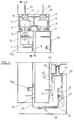
- the numbers 1 and 2 refer to the two leaves of a sliding door. These leaves are suspended from an upper shaped section 3 that forms two rails numbered 4 and 5. Running along the inside of these two rails are carriages 6 making up the rolling elements for sliding the doors 1 and 2.
- the carriages 6, figure 2 include a housing in which are mounted two parallel axis wheels 7. Between these two wheels is a central vertical hole 8 in which is inserted, from below, an intermediate rod 9 from which the leaves 1 and 2 are suspended by means of an intermediate plate 10.
- the vertical hole 8 of the carriage 6, and the central rod 9, can be secured together by means of screwing.
- the hole and the rod need not he threaded, in which case they both contain a transverse hole 8a, figures 4 and 12, so that a blocking pin can be inserted. If the rod 9 is threaded, it can have an unthreaded polygonal-shape intermediate section 11 so that it can be gripped with a spanner.
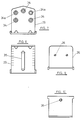
- plate 10 has a roughly rectangular shape with a central section 12 bent into a right angle from one of its longitudinal edges. On each side of this central section is a tab 13. Along the bending line of the section 12 is a notch 14 for the passage and proper positioning of the central rod 9, this notch aligning with the plate 10 via a window 15 sized to allow the head of the rod 9 to pass through. Moreover, the plate 10 has holes 17 to allow securing screws for leaves 1 and 2 to pass through and, as can be seen in figures 1 and 2, is also carries pivots 17a for it to be centred.
- the central section of the plate 10 is housed in a recess 12a made in the leaves 1 and 2 of the door along their upper edge.
- This system of mounting allows the height of the leaves 1 and 2 to be adjusted so that their upper edge is set as close to the upper rail 3 as is wished.
- the shaped piece 3 has a roughly rectangular outline, with an intermediate transverse partition 18 that defines two longitudinal gaps, each of which has a longitudinal slot for the passage of the central rod 9.
- the upper opposite side has a longitudinal recess 19 containing drilled holes for securing screws 20 to pass.
- Rails 4 and 5 are fitted with internal stops 21, figure 2, that limit the passage of the carriages 6.
- the stops 21 consist of a body 22 with a projecting arm 23.
- the stops are secured by means of a bridge 24, screws 25 traversing the body 22, and nuts 26 that are housed in that body.
- the ends of the side arms 27 of the bridges 24 are toothed 28.
- the stops 21 are mounted in such a way that the arm 23 points towards the carriage 6.
- the carriage 6 will knock against the body 22, while the adjacent wheel 7 couples with the arm 23, which acts as a retaining element to prevent the door from accidentally opening.
- the screws 25, resting on the bottom of the rail are pressed they exert a downward pressure on the bridge 24, which will rest with its teeth on the track of the rails.
- leaf number 1 occupies the outside position.
- a U-piece consisting of two brackets 29 and 30.
- the first bracket is secured to leaf 1 and the second carries the runners 31 which, along with the runners 32 secured directly to the inner door 2, slide along the inverted guide 33.
- Bracket 29 is shown in figures 7 and 8, and bracket 30 in figures 9 and 10.
- the vertical arm of bracket 29 is provided with holes 34 for the passage of the leaf 1 securing elements and the centring pivots 34a, while the other arm has a longitudinal slot.
- the vertical arm of bracket 30 has two holes 36 for securing a base 37 to which is mounted the runner 31. Its horizontal arm has a threaded hole 38 which fits over the slot 35 of bracket 29 to take a union screw 39, figure 1. This allows the slot 35 to vary the separation between the brackets in order to adjust the distance to the guide 33.
- Figure 1 shows a transverse cross-section of the guide 33, which consists of an inverted C-shape with side arms of different lengths.
- the shorter arm, number 40 is the one that is closer to the door leaves 1 and 2.
- the outside of the central arm of this guide 33 forms a longitudinal groove 41 with a central slot, along its whole length.
- the head of pivots 42 slide along this groove, these pivots being fixed underneath in an inverted position in the bottom 43 of the enclosure or gap that is closed by the doors.
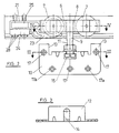
- Figure 11 shows the two coplanar leaves 1a and 2a linked by hinges 43 in order to form a folding door.
- Number 3a is the shaped single rail section along which runs the rolling element carriages 6.
- the leaf links with the side of the gap by means of a hinge 45 of a known design.
- leaf 2a links with the corresponding carriage by means of hinge 46.
- Figure 12 shows a vertical cross-section of shaped section 3a of figure 11, which forms a single rail along which run the carriages 6.
- the intermediate vertical rod 9a, and also the central hole in the carriage 6, are unthreaded, both elements having a transverse hole 8a that can be aligned to take a securing pin 47.
- the plate 10 of the mechanism in figures 1 and 2 is replaced by a bracket 48, figure 13, whose horizontal arm has a hole 49 for the rod 9a to pass. Its other arm has holes 50 for securing the hinge 46.
- the runners 31 are mounted via the base 37 to a piece 51 which is connected to a lower hinge 46.
- this piece 51 consists of a flat far bent into an L-shape, the shorter arm being extended laterally by a section 52 to which is secured the hinge 46.
- the longer arm 53 is provided with holes 54 for securing the base 37 on which is mounted the runner 31. This runner slides along the inverted guide 55.
- the shaped section creating the rail and the suspension pieces for the door and the runner mounting can be changed in order to mount a running or folding door, traditional hinges being used in the latter case.
Applications Claiming Priority (2)
| Application Number | Priority Date | Filing Date | Title |
|---|---|---|---|
| ES9100551A ES2028704A6 (es) | 1991-03-05 | 1991-03-05 | Mecanismo para el montaje de puertas deslizantes y plegables. |
| ES9100551 | 1991-03-05 |
Publications (2)
| Publication Number | Publication Date |
|---|---|
| EP0502285A1 true EP0502285A1 (de) | 1992-09-09 |
| EP0502285B1 EP0502285B1 (de) | 1996-03-27 |
Family
ID=8271467
Family Applications (1)
| Application Number | Title | Priority Date | Filing Date |
|---|---|---|---|
| EP91500046A Expired - Lifetime EP0502285B1 (de) | 1991-03-05 | 1991-05-21 | Vorrichtung zur Montage von Schiebetoren |
Country Status (6)
| Country | Link |
|---|---|
| EP (1) | EP0502285B1 (de) |
| AT (1) | ATE136090T1 (de) |
| DE (1) | DE69118355T2 (de) |
| DK (1) | DK0502285T3 (de) |
| ES (1) | ES2028704A6 (de) |
| GR (1) | GR3020334T3 (de) |
Cited By (11)
| Publication number | Priority date | Publication date | Assignee | Title |
|---|---|---|---|---|
| EP0753637A1 (de) * | 1995-07-13 | 1997-01-15 | Klein Iberica, S.A. | Struktur zum Anordnen von Schiebetüren |
| WO2000055460A1 (de) * | 1999-03-16 | 2000-09-21 | Hawa Ag | Puffervorrichtung |
| WO2000065186A1 (de) * | 1999-04-27 | 2000-11-02 | Hawa Ag | Aufhängevorrichtung |
| EP0984126A3 (de) * | 1998-09-03 | 2001-02-21 | Eku Ag | Führungsanordnung für eine Schiebetür |
| KR100377091B1 (ko) * | 2000-02-18 | 2003-03-29 | 명 규 박 | 현가식 도어용 이동 롤러의 높이 조절구조 |
| US7117559B1 (en) * | 2004-08-14 | 2006-10-10 | David Barber | Support system for pocket doors |
| EP2218858A1 (de) * | 2009-02-15 | 2010-08-18 | Hawa Ag | Laufwerk für eine Trennelement, Trennelement und Vorrichtung |
| EP2169164A3 (de) * | 2008-09-29 | 2012-06-27 | TIF GmbH | Halte- und Führungsvorrichtung für eine Schiebetür |
| WO2014174512A1 (en) * | 2013-04-22 | 2014-10-30 | Hardoor Top Design & Technology Ltd | System and device for soft closing |
| CN109339647A (zh) * | 2018-09-14 | 2019-02-15 | 大连金蝴蝶科技有限公司 | 双向错位式推拉开合机构 |
| CN109555419A (zh) * | 2019-01-07 | 2019-04-02 | 赵夏玲 | 一种滑移门及带有滑移门的单向门 |
Citations (12)
| Publication number | Priority date | Publication date | Assignee | Title |
|---|---|---|---|---|
| DE242447C (de) * | ||||
| FR1362519A (fr) * | 1963-03-28 | 1964-06-05 | Chariot pour porte à déplacement latéral | |
| US3289243A (en) * | 1965-03-19 | 1966-12-06 | Arthur Cox And Sons Inc | Sliding door hanger |
| DE1708277A1 (de) * | 1967-11-11 | 1971-05-19 | Ver Baubeschlag Gretsch Co | Aufhaengevorrichtung fuer Schiebewaende od. dgl. |
| DE1817951A1 (de) * | 1968-10-09 | 1975-03-13 | Ver Baubeschlag Gretsch Co | Befestigung von beschlagteilen in profilrahmen von fenstern, tueren od.dgl |
| DE2555289A1 (de) * | 1975-04-11 | 1976-10-21 | Haab | Vorrichtung zum aufhaengen von schiebetueren |
| DE2553175A1 (de) * | 1975-11-27 | 1977-06-08 | Geb Stoll Josephine Pfaehler | Rollenlagerung fuer eine doppel- schiebetueren-anordnung |
| EP0010220A1 (de) * | 1978-10-12 | 1980-04-30 | Inbauproduct Inter-IP AG | Schiebetürschrank |
| AT366902B (de) * | 1977-11-03 | 1982-05-25 | Blum Gmbh Julius | Schienengarnitur fuer schiebetueren |
| DE3238204A1 (de) * | 1982-10-15 | 1984-04-19 | Pauli & Sohn GmbH Metallwaren, 5220 Waldbröl | Vorrichtung zur haengenden anbringung von scheiben an einer laufschiene |
| CH657415A5 (en) * | 1982-09-01 | 1986-08-29 | Karl Haab | Sliding door with a holding device |
| EP0385045A1 (de) * | 1989-02-27 | 1990-09-05 | Klein Iberica, S.A. | Beschlag für Schiebetüren |
-
1991
- 1991-03-05 ES ES9100551A patent/ES2028704A6/es not_active Expired - Fee Related
- 1991-05-21 DK DK91500046.7T patent/DK0502285T3/da active
- 1991-05-21 AT AT91500046T patent/ATE136090T1/de not_active IP Right Cessation
- 1991-05-21 DE DE69118355T patent/DE69118355T2/de not_active Expired - Fee Related
- 1991-05-21 EP EP91500046A patent/EP0502285B1/de not_active Expired - Lifetime
-
1996
- 1996-06-25 GR GR960401703T patent/GR3020334T3/el unknown
Patent Citations (12)
| Publication number | Priority date | Publication date | Assignee | Title |
|---|---|---|---|---|
| DE242447C (de) * | ||||
| FR1362519A (fr) * | 1963-03-28 | 1964-06-05 | Chariot pour porte à déplacement latéral | |
| US3289243A (en) * | 1965-03-19 | 1966-12-06 | Arthur Cox And Sons Inc | Sliding door hanger |
| DE1708277A1 (de) * | 1967-11-11 | 1971-05-19 | Ver Baubeschlag Gretsch Co | Aufhaengevorrichtung fuer Schiebewaende od. dgl. |
| DE1817951A1 (de) * | 1968-10-09 | 1975-03-13 | Ver Baubeschlag Gretsch Co | Befestigung von beschlagteilen in profilrahmen von fenstern, tueren od.dgl |
| DE2555289A1 (de) * | 1975-04-11 | 1976-10-21 | Haab | Vorrichtung zum aufhaengen von schiebetueren |
| DE2553175A1 (de) * | 1975-11-27 | 1977-06-08 | Geb Stoll Josephine Pfaehler | Rollenlagerung fuer eine doppel- schiebetueren-anordnung |
| AT366902B (de) * | 1977-11-03 | 1982-05-25 | Blum Gmbh Julius | Schienengarnitur fuer schiebetueren |
| EP0010220A1 (de) * | 1978-10-12 | 1980-04-30 | Inbauproduct Inter-IP AG | Schiebetürschrank |
| CH657415A5 (en) * | 1982-09-01 | 1986-08-29 | Karl Haab | Sliding door with a holding device |
| DE3238204A1 (de) * | 1982-10-15 | 1984-04-19 | Pauli & Sohn GmbH Metallwaren, 5220 Waldbröl | Vorrichtung zur haengenden anbringung von scheiben an einer laufschiene |
| EP0385045A1 (de) * | 1989-02-27 | 1990-09-05 | Klein Iberica, S.A. | Beschlag für Schiebetüren |
Cited By (22)
| Publication number | Priority date | Publication date | Assignee | Title |
|---|---|---|---|---|
| EP0753637A1 (de) * | 1995-07-13 | 1997-01-15 | Klein Iberica, S.A. | Struktur zum Anordnen von Schiebetüren |
| EP0984126A3 (de) * | 1998-09-03 | 2001-02-21 | Eku Ag | Führungsanordnung für eine Schiebetür |
| WO2000055460A1 (de) * | 1999-03-16 | 2000-09-21 | Hawa Ag | Puffervorrichtung |
| US6438795B1 (en) | 1999-03-16 | 2002-08-27 | Hawa Ag | Buffer device |
| WO2000065186A1 (de) * | 1999-04-27 | 2000-11-02 | Hawa Ag | Aufhängevorrichtung |
| US6418588B1 (en) | 1999-04-27 | 2002-07-16 | Hawa Ag | Suspension device |
| AU765786B2 (en) * | 1999-04-27 | 2003-10-02 | Hawa Ag | Suspension device |
| CZ299560B6 (cs) * | 1999-04-27 | 2008-09-03 | Hawa Ag | Závesné ústrojí |
| KR100377091B1 (ko) * | 2000-02-18 | 2003-03-29 | 명 규 박 | 현가식 도어용 이동 롤러의 높이 조절구조 |
| US7117559B1 (en) * | 2004-08-14 | 2006-10-10 | David Barber | Support system for pocket doors |
| EP2169164A3 (de) * | 2008-09-29 | 2012-06-27 | TIF GmbH | Halte- und Führungsvorrichtung für eine Schiebetür |
| EP2660413A1 (de) * | 2008-09-29 | 2013-11-06 | TIF GmbH | Halte- und Führungsvorrichtung für eine Schiebetür |
| EP2218858A1 (de) * | 2009-02-15 | 2010-08-18 | Hawa Ag | Laufwerk für eine Trennelement, Trennelement und Vorrichtung |
| US8381354B2 (en) | 2009-02-15 | 2013-02-26 | Hawa Ag | Carriage for a separation element, separation element and device |
| CN101899938A (zh) * | 2009-02-15 | 2010-12-01 | 哈瓦有限公司 | 用于分隔构件的滑动机构、分隔构件以及装置 |
| CN101899938B (zh) * | 2009-02-15 | 2014-04-09 | 哈瓦有限公司 | 用于分隔构件的滑动机构、分隔构件以及装置 |
| WO2014174512A1 (en) * | 2013-04-22 | 2014-10-30 | Hardoor Top Design & Technology Ltd | System and device for soft closing |
| CN105308250A (zh) * | 2013-04-22 | 2016-02-03 | 哈多高级设计与技术有限公司 | 用于软关闭的系统及装置 |
| CN109339647A (zh) * | 2018-09-14 | 2019-02-15 | 大连金蝴蝶科技有限公司 | 双向错位式推拉开合机构 |
| CN109339647B (zh) * | 2018-09-14 | 2023-07-25 | 大连金蝴蝶科技有限公司 | 双向错位式推拉开合机构 |
| CN109555419A (zh) * | 2019-01-07 | 2019-04-02 | 赵夏玲 | 一种滑移门及带有滑移门的单向门 |
| CN109555419B (zh) * | 2019-01-07 | 2023-10-27 | 襄阳市思想机电科技有限公司 | 一种滑移门及带有滑移门的单向门 |
Also Published As
| Publication number | Publication date |
|---|---|
| DE69118355T2 (de) | 1996-11-21 |
| GR3020334T3 (en) | 1996-09-30 |
| DE69118355D1 (de) | 1996-05-02 |
| ES2028704A6 (es) | 1992-07-01 |
| DK0502285T3 (da) | 1996-08-12 |
| ATE136090T1 (de) | 1996-04-15 |
| EP0502285B1 (de) | 1996-03-27 |
Similar Documents
| Publication | Publication Date | Title |
|---|---|---|
| EP0502285A1 (de) | Vorrichtung zur Montage von Schiebetoren | |
| CA1272416A (en) | Combination pivot corner and slide guide for sash window | |
| US5395165A (en) | Suspension system for pocket-type doors | |
| CN101720377A (zh) | 用于滑动门的对准闭合的机构,尤其用于具有两个或更多门的家具单元或隔室的机构 | |
| ES2084543A2 (es) | Mecanismo para puertas corredizas de cristal. | |
| DE10212011C1 (de) | Mittels Tragrollen an einer Laufschiene hängend geführtes Schiebeelement | |
| EP0940542B1 (de) | Montagevorrichtung für Glasschiebetüren | |
| AU598549B2 (en) | Furniture door | |
| ATE261832T1 (de) | Schwenkschiebetür für fahrzeuge | |
| EP1630337B1 (de) | Mechanismus zum hängen und einstellen von falttüren | |
| ATE31776T1 (de) | Falttuer deren tuerblaetter verwindungssteif ausgebildet sind. | |
| ATE94252T1 (de) | Schiebetuer und ihr antriebsmechanismus. | |
| US6527352B2 (en) | Storage element | |
| IE913549A1 (en) | A sliding entry door | |
| CA2197762A1 (en) | Screen of the type having two or more overlapping sliding leaves | |
| GB2431684A (en) | Extending top rail for sliding door | |
| DE2716988B2 (de) | Vorrichtung zum Ausgleichen des Gewichts von Toren | |
| EP1176113A1 (de) | Einschienenführungssysteem für Aufzugstüren | |
| NL1021384C2 (nl) | Scharnierbare ophanging voor een deur en deur voorzien van zulke ophanging. | |
| DK537486A (da) | Beslag til en i form af et vindue, doere eller lignende udformet skydelag | |
| AU2002302076A1 (en) | Concertina panel wall | |
| GB2344845A (en) | Hinged sliding sash window | |
| SI1630332T1 (sl) | Ĺ arnirni sistem za zloĺ˝ljiva vrata | |
| DD291114A5 (de) | Laufwagen fuer falttueren | |
| EP2186981A1 (de) | Vorrichtung zur Befestigung von Führungsschienen für Sektionaltore |
Legal Events
| Date | Code | Title | Description |
|---|---|---|---|
| PUAI | Public reference made under article 153(3) epc to a published international application that has entered the european phase |
Free format text: ORIGINAL CODE: 0009012 |
|
| AK | Designated contracting states |
Kind code of ref document: A1 Designated state(s): AT BE CH DE DK FR GB GR IT LI LU NL SE |
|
| 17P | Request for examination filed |
Effective date: 19930226 |
|
| 17Q | First examination report despatched |
Effective date: 19941031 |
|
| GRAA | (expected) grant |
Free format text: ORIGINAL CODE: 0009210 |
|
| AK | Designated contracting states |
Kind code of ref document: B1 Designated state(s): AT BE CH DE DK FR GB GR IT LI LU NL SE |
|
| REF | Corresponds to: |
Ref document number: 136090 Country of ref document: AT Date of ref document: 19960415 Kind code of ref document: T |
|
| REF | Corresponds to: |
Ref document number: 69118355 Country of ref document: DE Date of ref document: 19960502 |
|
| ITF | It: translation for a ep patent filed |
Owner name: STUDIO TORTA SOCIETA' SEMPLICE |
|
| REG | Reference to a national code |
Ref country code: CH Ref legal event code: NV Representative=s name: HEPP, WENGER & RYFFEL AG |
|
| ET | Fr: translation filed | ||
| REG | Reference to a national code |
Ref country code: DK Ref legal event code: T3 |
|
| REG | Reference to a national code |
Ref country code: GR Ref legal event code: FG4A Free format text: 3020334 |
|
| PLBE | No opposition filed within time limit |
Free format text: ORIGINAL CODE: 0009261 |
|
| STAA | Information on the status of an ep patent application or granted ep patent |
Free format text: STATUS: NO OPPOSITION FILED WITHIN TIME LIMIT |
|
| 26N | No opposition filed | ||
| REG | Reference to a national code |
Ref country code: GB Ref legal event code: IF02 |
|
| REG | Reference to a national code |
Ref country code: DK Ref legal event code: EBP |
|
| PG25 | Lapsed in a contracting state [announced via postgrant information from national office to epo] |
Ref country code: DK Free format text: LAPSE BECAUSE OF NON-PAYMENT OF DUE FEES Effective date: 20080531 |
|
| REG | Reference to a national code |
Ref country code: DK Ref legal event code: EGE |
|
| PGFP | Annual fee paid to national office [announced via postgrant information from national office to epo] |
Ref country code: DK Payment date: 20090514 Year of fee payment: 19 Ref country code: NL Payment date: 20090424 Year of fee payment: 19 |
|
| PGFP | Annual fee paid to national office [announced via postgrant information from national office to epo] |
Ref country code: LU Payment date: 20090423 Year of fee payment: 19 Ref country code: DE Payment date: 20090520 Year of fee payment: 19 Ref country code: AT Payment date: 20090526 Year of fee payment: 19 Ref country code: FR Payment date: 20090417 Year of fee payment: 19 Ref country code: IT Payment date: 20090521 Year of fee payment: 19 Ref country code: SE Payment date: 20090525 Year of fee payment: 19 |
|
| PGFP | Annual fee paid to national office [announced via postgrant information from national office to epo] |
Ref country code: BE Payment date: 20090506 Year of fee payment: 19 |
|
| PGFP | Annual fee paid to national office [announced via postgrant information from national office to epo] |
Ref country code: GB Payment date: 20090520 Year of fee payment: 19 Ref country code: GR Payment date: 20090430 Year of fee payment: 19 Ref country code: CH Payment date: 20090716 Year of fee payment: 19 |
|
| BERE | Be: lapsed |
Owner name: S.A. *KLEIN IBERICA Effective date: 20100531 |
|
| REG | Reference to a national code |
Ref country code: NL Ref legal event code: V1 Effective date: 20101201 |
|
| REG | Reference to a national code |
Ref country code: CH Ref legal event code: PL |
|
| REG | Reference to a national code |
Ref country code: DK Ref legal event code: EBP |
|
| GBPC | Gb: european patent ceased through non-payment of renewal fee |
Effective date: 20100521 |
|
| PG25 | Lapsed in a contracting state [announced via postgrant information from national office to epo] |
Ref country code: AT Free format text: LAPSE BECAUSE OF NON-PAYMENT OF DUE FEES Effective date: 20100521 |
|
| EUG | Se: european patent has lapsed | ||
| REG | Reference to a national code |
Ref country code: FR Ref legal event code: ST Effective date: 20110131 |
|
| PG25 | Lapsed in a contracting state [announced via postgrant information from national office to epo] |
Ref country code: LI Free format text: LAPSE BECAUSE OF NON-PAYMENT OF DUE FEES Effective date: 20100531 Ref country code: CH Free format text: LAPSE BECAUSE OF NON-PAYMENT OF DUE FEES Effective date: 20100531 |
|
| PG25 | Lapsed in a contracting state [announced via postgrant information from national office to epo] |
Ref country code: BE Free format text: LAPSE BECAUSE OF NON-PAYMENT OF DUE FEES Effective date: 20100531 Ref country code: IT Free format text: LAPSE BECAUSE OF NON-PAYMENT OF DUE FEES Effective date: 20100521 Ref country code: GR Free format text: LAPSE BECAUSE OF NON-PAYMENT OF DUE FEES Effective date: 20101202 Ref country code: SE Free format text: LAPSE BECAUSE OF NON-PAYMENT OF DUE FEES Effective date: 20100522 Ref country code: NL Free format text: LAPSE BECAUSE OF NON-PAYMENT OF DUE FEES Effective date: 20101201 |
|
| PG25 | Lapsed in a contracting state [announced via postgrant information from national office to epo] |
Ref country code: DK Free format text: LAPSE BECAUSE OF NON-PAYMENT OF DUE FEES Effective date: 20100531 Ref country code: DE Free format text: LAPSE BECAUSE OF NON-PAYMENT OF DUE FEES Effective date: 20101201 |
|
| PG25 | Lapsed in a contracting state [announced via postgrant information from national office to epo] |
Ref country code: FR Free format text: LAPSE BECAUSE OF NON-PAYMENT OF DUE FEES Effective date: 20100531 |
|
| PG25 | Lapsed in a contracting state [announced via postgrant information from national office to epo] |
Ref country code: GB Free format text: LAPSE BECAUSE OF NON-PAYMENT OF DUE FEES Effective date: 20100521 |
|
| PG25 | Lapsed in a contracting state [announced via postgrant information from national office to epo] |
Ref country code: LU Free format text: LAPSE BECAUSE OF NON-PAYMENT OF DUE FEES Effective date: 20100521 |