EP0385045A1 - Beschlag für Schiebetüren - Google Patents
Beschlag für Schiebetüren Download PDFInfo
- Publication number
- EP0385045A1 EP0385045A1 EP89500083A EP89500083A EP0385045A1 EP 0385045 A1 EP0385045 A1 EP 0385045A1 EP 89500083 A EP89500083 A EP 89500083A EP 89500083 A EP89500083 A EP 89500083A EP 0385045 A1 EP0385045 A1 EP 0385045A1
- Authority
- EP
- European Patent Office
- Prior art keywords
- panels
- panel
- fixed
- pads
- guides
- Prior art date
- Legal status (The legal status is an assumption and is not a legal conclusion. Google has not performed a legal analysis and makes no representation as to the accuracy of the status listed.)
- Granted
Links
Images


Classifications
-
- E—FIXED CONSTRUCTIONS
- E05—LOCKS; KEYS; WINDOW OR DOOR FITTINGS; SAFES
- E05F—DEVICES FOR MOVING WINGS INTO OPEN OR CLOSED POSITION; CHECKS FOR WINGS; WING FITTINGS NOT OTHERWISE PROVIDED FOR, CONCERNED WITH THE FUNCTIONING OF THE WING
- E05F5/00—Braking devices, e.g. checks; Stops; Buffers
- E05F5/003—Braking devices, e.g. checks; Stops; Buffers for sliding wings
-
- E—FIXED CONSTRUCTIONS
- E05—LOCKS; KEYS; WINDOW OR DOOR FITTINGS; SAFES
- E05B—LOCKS; ACCESSORIES THEREFOR; HANDCUFFS
- E05B65/00—Locks or fastenings for special use
- E05B65/08—Locks or fastenings for special use for sliding wings
-
- E—FIXED CONSTRUCTIONS
- E05—LOCKS; KEYS; WINDOW OR DOOR FITTINGS; SAFES
- E05C—BOLTS OR FASTENING DEVICES FOR WINGS, SPECIALLY FOR DOORS OR WINDOWS
- E05C19/00—Other devices specially designed for securing wings, e.g. with suction cups
- E05C19/06—Other devices specially designed for securing wings, e.g. with suction cups in which the securing part if formed or carried by a spring and moves only by distortion of the spring, e.g. snaps
- E05C19/063—Released by pull or pressure on the wing
- E05C19/066—Released by pull or pressure on the wing made of plastics, e.g. hook-and-loop type fastener
-
- E—FIXED CONSTRUCTIONS
- E05—LOCKS; KEYS; WINDOW OR DOOR FITTINGS; SAFES
- E05D—HINGES OR SUSPENSION DEVICES FOR DOORS, WINDOWS OR WINGS
- E05D15/00—Suspension arrangements for wings
- E05D15/06—Suspension arrangements for wings for wings sliding horizontally more or less in their own plane
-
- E—FIXED CONSTRUCTIONS
- E05—LOCKS; KEYS; WINDOW OR DOOR FITTINGS; SAFES
- E05D—HINGES OR SUSPENSION DEVICES FOR DOORS, WINDOWS OR WINGS
- E05D15/00—Suspension arrangements for wings
- E05D15/06—Suspension arrangements for wings for wings sliding horizontally more or less in their own plane
- E05D15/0621—Details, e.g. suspension or supporting guides
- E05D15/0626—Details, e.g. suspension or supporting guides for wings suspended at the top
- E05D15/063—Details, e.g. suspension or supporting guides for wings suspended at the top on wheels with fixed axis
- E05D15/0634—Details, e.g. suspension or supporting guides for wings suspended at the top on wheels with fixed axis with height adjustment
-
- E—FIXED CONSTRUCTIONS
- E05—LOCKS; KEYS; WINDOW OR DOOR FITTINGS; SAFES
- E05D—HINGES OR SUSPENSION DEVICES FOR DOORS, WINDOWS OR WINGS
- E05D15/00—Suspension arrangements for wings
- E05D15/06—Suspension arrangements for wings for wings sliding horizontally more or less in their own plane
- E05D15/08—Suspension arrangements for wings for wings sliding horizontally more or less in their own plane consisting of two or more independent parts movable each in its own guides
-
- E—FIXED CONSTRUCTIONS
- E05—LOCKS; KEYS; WINDOW OR DOOR FITTINGS; SAFES
- E05D—HINGES OR SUSPENSION DEVICES FOR DOORS, WINDOWS OR WINGS
- E05D15/00—Suspension arrangements for wings
- E05D15/06—Suspension arrangements for wings for wings sliding horizontally more or less in their own plane
- E05D15/0621—Details, e.g. suspension or supporting guides
- E05D15/0626—Details, e.g. suspension or supporting guides for wings suspended at the top
- E05D15/0656—Bottom guides
-
- E—FIXED CONSTRUCTIONS
- E05—LOCKS; KEYS; WINDOW OR DOOR FITTINGS; SAFES
- E05Y—INDEXING SCHEME RELATING TO HINGES OR OTHER SUSPENSION DEVICES FOR DOORS, WINDOWS OR WINGS AND DEVICES FOR MOVING WINGS INTO OPEN OR CLOSED POSITION, CHECKS FOR WINGS AND WING FITTINGS NOT OTHERWISE PROVIDED FOR, CONCERNED WITH THE FUNCTIONING OF THE WING
- E05Y2201/00—Constructional elements; Accessories therefore
- E05Y2201/20—Brakes; Disengaging means, e.g. clutches; Holders, e.g. locks; Stops; Accessories therefore
- E05Y2201/218—Holders
-
- E—FIXED CONSTRUCTIONS
- E05—LOCKS; KEYS; WINDOW OR DOOR FITTINGS; SAFES
- E05Y—INDEXING SCHEME RELATING TO HINGES OR OTHER SUSPENSION DEVICES FOR DOORS, WINDOWS OR WINGS AND DEVICES FOR MOVING WINGS INTO OPEN OR CLOSED POSITION, CHECKS FOR WINGS AND WING FITTINGS NOT OTHERWISE PROVIDED FOR, CONCERNED WITH THE FUNCTIONING OF THE WING
- E05Y2201/00—Constructional elements; Accessories therefore
- E05Y2201/40—Motors; Magnets; Springs; Weights; Accessories therefore
- E05Y2201/47—Springs; Spring tensioners
- E05Y2201/48—Leaf springs
-
- E—FIXED CONSTRUCTIONS
- E05—LOCKS; KEYS; WINDOW OR DOOR FITTINGS; SAFES
- E05Y—INDEXING SCHEME RELATING TO HINGES OR OTHER SUSPENSION DEVICES FOR DOORS, WINDOWS OR WINGS AND DEVICES FOR MOVING WINGS INTO OPEN OR CLOSED POSITION, CHECKS FOR WINGS AND WING FITTINGS NOT OTHERWISE PROVIDED FOR, CONCERNED WITH THE FUNCTIONING OF THE WING
- E05Y2800/00—Details, accessories and auxiliary operations not otherwise provided for
- E05Y2800/73—Single use of elements
-
- E—FIXED CONSTRUCTIONS
- E05—LOCKS; KEYS; WINDOW OR DOOR FITTINGS; SAFES
- E05Y—INDEXING SCHEME RELATING TO HINGES OR OTHER SUSPENSION DEVICES FOR DOORS, WINDOWS OR WINGS AND DEVICES FOR MOVING WINGS INTO OPEN OR CLOSED POSITION, CHECKS FOR WINGS AND WING FITTINGS NOT OTHERWISE PROVIDED FOR, CONCERNED WITH THE FUNCTIONING OF THE WING
- E05Y2900/00—Application of doors, windows, wings or fittings thereof
- E05Y2900/10—Application of doors, windows, wings or fittings thereof for buildings or parts thereof
- E05Y2900/13—Application of doors, windows, wings or fittings thereof for buildings or parts thereof characterised by the type of wing
- E05Y2900/132—Doors
-
- E—FIXED CONSTRUCTIONS
- E05—LOCKS; KEYS; WINDOW OR DOOR FITTINGS; SAFES
- E05Y—INDEXING SCHEME RELATING TO HINGES OR OTHER SUSPENSION DEVICES FOR DOORS, WINDOWS OR WINGS AND DEVICES FOR MOVING WINGS INTO OPEN OR CLOSED POSITION, CHECKS FOR WINGS AND WING FITTINGS NOT OTHERWISE PROVIDED FOR, CONCERNED WITH THE FUNCTIONING OF THE WING
- E05Y2900/00—Application of doors, windows, wings or fittings thereof
- E05Y2900/20—Application of doors, windows, wings or fittings thereof for furnitures, e.g. cabinets
Definitions
- the present invention refers to a fitting for sliding doors, which can be applied to sliding doors with one panel or with more than two, each of which having elements of upper bearings and lower pads, movable on fixed tracks provided bumpers that limit the movement of the panels.
- Fittings for sliding doors are already known, of the type indicated, in which the tracks on which the upper rolling elements move consist of profiles which are fixed to the internal surface of the ceiling of the empty space. that the door closes.
- the doors include two panels, it is necessary to have two parallel profiles, one for each door. With this traditional constitution, the doors remain suspended from the profile, having to support the entire weight of the door.
- the screws and the fastening elements of the mentioned profiles are used to loosen, which causes the profile to lose its horizontality, giving rise to a faulty operation which can cause jamming and blocking of the doors, noise when moving, etc ...
- the object of the present invention is to develop a fitting which allows simple assembly both of its components and of the door panels.
- Another object of the invention is to obtain a fitting with which a smooth displacement of the panels is obtained and silent and moreover without risk of misalignments or unevenness of its components, thereby ensuring operation perfect of the whole.
- the fitting of the invention also allows the mounting of doors which completely cover the front of the empty space to be closed, from floor to ceiling of the room or enclosure, obtaining better effects in the finishing and aspect of said enclosure.
- fitting of the invention can be used for doors having a panel, given its constitution and its operational safety, it is of special application for sliding doors having two or more panels.
- the tracks on which the rolling elements and the pads will move consist of an upper rail and a lower guide, if the door has only one panel, or two parallel upper rails and close to each other and to two lower guides, also parallel and close to each other, if the door has 2 or more panels.
- the rails and the guides are arranged respectively on the external surface of the ceiling and of the bottom of the void to be closed, the rail and the outermost guide remaining located in position adjacent to the edge of the areas mentioned. .
- the bumpers that limit the movement of the door panels include an anchoring base, a vertical plate and a union angle.
- the anchoring base is fixed to the external surface of the ceiling and melts in position adjacent to the rails and guides.
- the vertical plate is of adjustable position, parallel to the rails and the guides, and is fixed to the anchoring base, having, from its vertical edges, means for retaining the rolling elements and buffers for the pads.
- the union angle serves as a base for threading the screws fixing the plate to the anchoring base.
- the upper rolling elements consist of rollers with peripheral grooves, which are mounted, by means of bearings, on an axis which is integral with a vertical plate and close to said pulley.
- This plate is fixed directly to the internal surface of the door panel closest to the empty space to be closed, for the support of the roller on the outermost rail, while the fixing to the door farthest from the hole to close, the fixing is carried out by means of a bridge which saves the outermost rail and locates the roller on the innermost rail or distant from the door.
- the lower runners include an anchoring core, a body with a profile which can be assembled to the guide and the anchoring core, and an opening limiting stopper.
- the anchoring core is fixed directly to the internal surface of the door panel closest to the empty space to be closed for coupling the body cited to the outermost guide, while its fixing to the most distant door vacuum to be closed is effected by means of a bridge which locates the body of the skate on the innermost or distant guide from the panels.
- the stops of the rail and external guide are arranged between the profiles which define the upper rails and the two lower guides, while the stops of the rail and internal guide are arranged on the extension of said rail and guide.
- the anchoring base mentioned above of the bumpers is composed of a piece of L-shaped section, on the concave surface of which the union angle, of metallic nature, is coupled. This part has on the outer surface of one of its branches of teeth or transverse ridges.
- the vertical plate of the bumpers it includes a lower zone, provided on one of its surfaces with teeth or vertical ridges, and an upper zone which has, from its vertical edges, opposite notches provided with means for retaining the elements of rolling.
- the plate and the anchoring base are fixed by means of screws which are screwed onto threaded orifices of the union angle, the teeth of the vertical plate remaining attached to those of the anchoring base, the relative position between the two elements being adjustable thanks to these teeth.
- the axis of one of the upper rollers or pulleys of each panel protrudes from the free area thereof in a portion which remains opposite the notches in the vertical plate of the stops, so that when the panels are in the limit position for closing or opening, the portion which already protrudes above mentioned from the axis of the pulleys is introduced into the notches until it is located behind the retaining means of the latter, where they define nesting positions , being necessary to exert a slight effort to obtain the release of the extension of the axis and be able to initiate the movement of the panel.
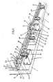
- the door consists of two panels bearing the numbers 1 and 2.
- FIGS. 1 and 2 the upper mechanisms of the fitting of the invention are shown. These mechanisms include rolling elements which consist of rollers or pulleys 3 with peripheral grooves, each of which is mounted on a support plate 4, as will be described below.
- rolling elements consist of rollers or pulleys 3 with peripheral grooves, each of which is mounted on a support plate 4, as will be described below.
- On the rear surface of the innermost panel 2 are directly fixed two rollers 3 by means of their plates 4.
- the rollers 3 can move on tracks formed by two rails 6 which are fixed to the external surface of the ceiling 7 of the empty space to be closed.
- These rails consist of an L-shaped profile which includes a flat branch 8 provided with orifices for the passage of fixing screws 9.
- the other branch 10 of these profiles is of larger size and has a rounded cross section , of radius approximately similar to or slightly less than that of the groove of the rollers 3.
- these sections 6 have on the branch 10 and from the external surface of the branch 8 a channel 11 on which a straightening core and connecting successive sections.
- the outermost rail 10 remains located adjacent to the free edge of the ceiling 7.
- the rollers or pulleys 3 are mounted on the support plate 4 by means of a bearing 13.
- the plate 4 has, on its rear surface, d 'a projection or pivot 14 and at one and the other end thereof, at different distance, from two grooves 15 and 16 of different length, of arcuate layout with center on the pivot 14.
- the pivot 14 is introduced into an orifice made in the panel 2 or on the bridges 5.
- the plate 4 is fixed by means of screws introduced through the grooves 15 and 16, their position and height being adjustable by turning it on the pivot 14, thanks to the size of the grooves 15 and 16.
- the screws 17, FIG. 1 are tightened to fix the plate 4 to the panel 2 and bridges 5.
- One of the rollers of each panel in this case one of the rollers 3 fixed to one of the bridges 5 and in the other one of the rollers 3 fixed to the panel 2, have, as an extension of its axis, a projection 18, which will serve to ensure the limit position for opening and closing the door panels.
- the bridges 5 are composed of folded U-shaped plates, which are fixed by one of their lateral branches to the internal surface of the door 5, while on the other lateral branch, the plates 4 carrying the rollers are fixed. 3.
- pivots 19 can protrude which are introduced in practical orifices from the internal surface of said panel 1, to serve as positioning elements to facilitate the mounting of the bridges.
- This mechanism includes two guides 20 parallel and close to each other, which are fixed to the bottom surface of the bottom 21 of the void to be closed.
- the outermost guide is placed in position adjacent to the free edge of the bottom 21.
- These guides are made up of L-shaped profiles, one of the branches of which, bearing the number 22, is completely flat and is attached to the outer surface of the bottom 21, to which it is fixed by means of screws 22 which pass through holes made on said branch.
- the other branch 23 of these profiles at its starting point a widening 24 on which a channel 25 is formed which opens onto the external surface of the branch 22, to introduce rectifier and connection guides, as in the case of the rails 6
- buffers 12 As in the case of Figures 1 and 2, between the guides 20 there are buffers 12 of similar constitution, which will serve to limit the maximum opening and closing position.
- the pads 26, as can be clearly seen in Figure 7, consist of an anchor core 27 and a body 28 with a profile that can be assembled to the branch 23 of the guides 20.
- a shoe of each panel further includes a stopper 29, which limits the opening and closing of the panels.
- the core 27 is fixed to the bridges 5 and to the panel 2 by means of screws 30, FIG. 7, while the body 28 is mounted on the core 27 by sliding.
- the screws 30 also serve for fixing the stopper 29, formed by a flat iron forming a right angle.
- the housing of the body 28, for its coupling to the core 27, is limited, as can be appreciated very well in FIG. 8, by flexible tongues 31, directed one towards each side, which are completed at their extremity in half arrowhead and which will serve as buffers to prevent relative sliding between the core 27 and the body 28, once the two parts are coupled.
- the buffers 12, as can be appreciated very well in FIGS. 1 and 6, are each formed by an anchoring base 32, which is fixed directly to the external surface of the ceiling 7 and bottom 21, in position adjacent to the rails 6 and guides 20, by a vertical plate 33 of adjustable position, and by a union angle 32a.
- the anchoring base 32 is formed by an L-shaped section piece, the branches of which have a different length.
- the longest branch 35 has holes 36 for the passage of the fixing screws to the external surface of the ceiling and bottom.
- the other branch, bearing the number 37, has vertical ridges 38 on its outer surface, as well as two horizontal grooves 39.
- the vertical plate 33 has on one of its sur faces of a groove 40 which can be assembled on the groove 38 of the anchoring base 32.
- This plate has more than two orifices 41 for the passage of fixing screws to the anchoring base.
- the union angle 32a mates on the concave surface of the anchoring base 32 and has threaded orifices to receive screws introduced through the holes 39 of the anchoring base 32 and orifices 41 of the plate 33, for their mutual union.
- the position of the plate 33 can be adjusted relative to the anchoring base 32, this being due to the grooves 39 of the anchoring base, the plate remaining locked by tightening the fixing screws to said base, by means of the ridges 38 and 40 opposables of the base and plate.
- the plate 33 has, from its vertical edges, notches 43 which remain superiorly limited by elastically deformable fasteners 45, which have transverse deviations on the end portion which determine an armrest angular 46, with the convexity directed towards the notch 43, partially closing it, to define the means for retaining the upper rollers.
- the fasteners 45 terminate on an end section 47 directed in an upward direction.
- the displacement of the panels 1 and 2 of the door is very easily obtained, this being due to the upper rolling elements and to the pads and lower guides.
- the weight of the door panels is supported by the ceiling 7 of the empty space to be closed.
- the opening and closing limit positions remain perfectly defined by means of the stops 12.
- the body 28 of the pads has externally on its upper and lower edges each of the grooves 48 and 49 of different depth, determined by the different height of the walls 50 which limit said grooves .
- This causes the mouth of one and the other channel and the edge of the walls which limit these, to remain located at a different distance from the mean longitudinal plane of the skid and, consequently, from the axis of the fixing screw 30.
- This constitution makes it possible to absorb possible mounting errors, by placing the body 28 of the pads on the position shown in the drawing or in the inverted position.
- the description of the fitting was made in relation to a type of door, but it can also be used in the case of interior doors.
- the rail or rails 6 would be arranged on the lower part on the ground to support the weight of the door by means of the rolling elements 3, which would be fixed to its lower part, while the guides 20 would be fixed to the upper part opposite to the corresponding rails, to cooperate with the pads 26 which would be fixed to the inner upper part of the door.
Priority Applications (1)
| Application Number | Priority Date | Filing Date | Title |
|---|---|---|---|
| AT89500083T ATE99021T1 (de) | 1989-02-27 | 1989-08-02 | Beschlag fuer schiebetueren. |
Applications Claiming Priority (2)
| Application Number | Priority Date | Filing Date | Title |
|---|---|---|---|
| ES8900703 | 1989-02-27 | ||
| ES8900703A ES2012667A6 (es) | 1989-02-27 | 1989-02-27 | Herraje para puertas correderas. |
Publications (2)
| Publication Number | Publication Date |
|---|---|
| EP0385045A1 true EP0385045A1 (de) | 1990-09-05 |
| EP0385045B1 EP0385045B1 (de) | 1993-12-22 |
Family
ID=8260650
Family Applications (1)
| Application Number | Title | Priority Date | Filing Date |
|---|---|---|---|
| EP89500083A Expired - Lifetime EP0385045B1 (de) | 1989-02-27 | 1989-08-02 | Beschlag für Schiebetüren |
Country Status (5)
| Country | Link |
|---|---|
| EP (1) | EP0385045B1 (de) |
| JP (1) | JPH0730650B2 (de) |
| AT (1) | ATE99021T1 (de) |
| DE (1) | DE68911670T2 (de) |
| ES (1) | ES2012667A6 (de) |
Cited By (9)
| Publication number | Priority date | Publication date | Assignee | Title |
|---|---|---|---|---|
| EP0502285A1 (de) * | 1991-03-05 | 1992-09-09 | Klein Iberica, S.A. | Vorrichtung zur Montage von Schiebetoren |
| EP0626495A1 (de) * | 1993-03-26 | 1994-11-30 | Klein Iberica, S.A. | Mechanismus für Glasschiebetüren |
| EP1028214A2 (de) * | 1999-02-09 | 2000-08-16 | Bauelemente Kontakt GmbH & Co. Kg | Schiebetüranordnung |
| WO2008031472A1 (de) * | 2006-09-15 | 2008-03-20 | Hermann Francksen Nachf. Gmbh & Co. Kg | Vorrichtung zur verfahrbaren anordnung einer schiebetür |
| WO2008028945A3 (en) * | 2006-09-06 | 2008-09-25 | Liexco Sa | Modular rail system for suspending sliding doors and sliding door system with user accessible braking / stopping element |
| EP2098669A1 (de) | 2008-03-03 | 2009-09-09 | Edac | Führungsvorrichtung für Taschentür |
| CN102383672A (zh) * | 2011-07-18 | 2012-03-21 | 佛山市顺德暨德科技有限公司 | 一种具备指纹识别功能的双锁锁具 |
| EP2336468A3 (de) * | 2009-12-18 | 2014-05-28 | Hettich-Heinze GmbH & Co. KG | Beschlaggarnitur für zwei Schiebetürflügel |
| PL126754U1 (pl) * | 2017-11-03 | 2019-05-06 | Valcomp Spolka Z Ograniczona Odpowiedzialnoscia | Przesuwny stoper amortyzujący |
Families Citing this family (7)
| Publication number | Priority date | Publication date | Assignee | Title |
|---|---|---|---|---|
| JP2549759B2 (ja) * | 1990-10-30 | 1996-10-30 | 松下電工株式会社 | 扉開閉装置 |
| JP3008316U (ja) * | 1994-03-22 | 1995-03-14 | 株式会社末廣産業 | 高さ調整可能ローラー |
| KR200460854Y1 (ko) * | 2008-08-29 | 2012-06-11 | 주식회사 바로크주방가구 | 주방가구의 도어 고정구 |
| KR200465354Y1 (ko) * | 2012-05-11 | 2013-02-14 | 권오성 | 수납장의 슬라이딩 도어용 가이드 스톱부재 |
| CA2964538C (en) * | 2016-04-13 | 2018-05-15 | 1925Workbench Ltd. | Rail-mounted doors |
| RU207309U1 (ru) * | 2021-04-28 | 2021-10-21 | Данил Юрьевич Онищенко | Стопор |
| KR102537718B1 (ko) * | 2022-07-11 | 2023-05-31 | 주식회사 비쓰리이앤에스 | 곡면 슬라이딩 도어가 구비된 원통형 고압산소챔버 |
Citations (5)
| Publication number | Priority date | Publication date | Assignee | Title |
|---|---|---|---|---|
| US3159866A (en) * | 1962-05-31 | 1964-12-08 | Acme Appliance Mfg Company | Vertically adjustable sliding door hanger |
| DE2614810A1 (de) * | 1976-04-06 | 1977-10-20 | Heinze Fa R | Halte- und fuehrungsvorrichtung fuer schiebetueren |
| EP0010220A1 (de) * | 1978-10-12 | 1980-04-30 | Inbauproduct Inter-IP AG | Schiebetürschrank |
| US4322914A (en) * | 1979-11-20 | 1982-04-06 | State Wide Aluminum Of Indiana, Inc. | Slideable closure construction |
| GB2164691A (en) * | 1984-09-20 | 1986-03-26 | Kermi Gmbh | Sliding-door partition for a shower |
-
1989
- 1989-02-27 ES ES8900703A patent/ES2012667A6/es not_active Expired - Fee Related
- 1989-08-02 EP EP89500083A patent/EP0385045B1/de not_active Expired - Lifetime
- 1989-08-02 DE DE68911670T patent/DE68911670T2/de not_active Expired - Lifetime
- 1989-08-02 AT AT89500083T patent/ATE99021T1/de not_active IP Right Cessation
- 1989-10-17 JP JP1270144A patent/JPH0730650B2/ja not_active Expired - Lifetime
Patent Citations (5)
| Publication number | Priority date | Publication date | Assignee | Title |
|---|---|---|---|---|
| US3159866A (en) * | 1962-05-31 | 1964-12-08 | Acme Appliance Mfg Company | Vertically adjustable sliding door hanger |
| DE2614810A1 (de) * | 1976-04-06 | 1977-10-20 | Heinze Fa R | Halte- und fuehrungsvorrichtung fuer schiebetueren |
| EP0010220A1 (de) * | 1978-10-12 | 1980-04-30 | Inbauproduct Inter-IP AG | Schiebetürschrank |
| US4322914A (en) * | 1979-11-20 | 1982-04-06 | State Wide Aluminum Of Indiana, Inc. | Slideable closure construction |
| GB2164691A (en) * | 1984-09-20 | 1986-03-26 | Kermi Gmbh | Sliding-door partition for a shower |
Cited By (13)
| Publication number | Priority date | Publication date | Assignee | Title |
|---|---|---|---|---|
| EP0502285A1 (de) * | 1991-03-05 | 1992-09-09 | Klein Iberica, S.A. | Vorrichtung zur Montage von Schiebetoren |
| EP0626495A1 (de) * | 1993-03-26 | 1994-11-30 | Klein Iberica, S.A. | Mechanismus für Glasschiebetüren |
| US5450693A (en) * | 1993-03-26 | 1995-09-19 | Klein Iberica S.A | Mechanism for sliding glass doors |
| EP1028214A2 (de) * | 1999-02-09 | 2000-08-16 | Bauelemente Kontakt GmbH & Co. Kg | Schiebetüranordnung |
| EP1028214A3 (de) * | 1999-02-09 | 2003-05-28 | Bauelemente Kontakt GmbH & Co. Kg | Schiebetüranordnung |
| WO2008028945A3 (en) * | 2006-09-06 | 2008-09-25 | Liexco Sa | Modular rail system for suspending sliding doors and sliding door system with user accessible braking / stopping element |
| US9003713B2 (en) | 2006-09-06 | 2015-04-14 | Rubelko | Modular rail system for suspending sliding doors and sliding door system with user accessible braking/stopping element |
| WO2008031472A1 (de) * | 2006-09-15 | 2008-03-20 | Hermann Francksen Nachf. Gmbh & Co. Kg | Vorrichtung zur verfahrbaren anordnung einer schiebetür |
| EP2098669A1 (de) | 2008-03-03 | 2009-09-09 | Edac | Führungsvorrichtung für Taschentür |
| EP2336468A3 (de) * | 2009-12-18 | 2014-05-28 | Hettich-Heinze GmbH & Co. KG | Beschlaggarnitur für zwei Schiebetürflügel |
| CN102383672A (zh) * | 2011-07-18 | 2012-03-21 | 佛山市顺德暨德科技有限公司 | 一种具备指纹识别功能的双锁锁具 |
| CN102383672B (zh) * | 2011-07-18 | 2013-07-17 | 佛山市顺德暨德科技有限公司 | 一种具备指纹识别功能的双锁锁具 |
| PL126754U1 (pl) * | 2017-11-03 | 2019-05-06 | Valcomp Spolka Z Ograniczona Odpowiedzialnoscia | Przesuwny stoper amortyzujący |
Also Published As
| Publication number | Publication date |
|---|---|
| JPH0730650B2 (ja) | 1995-04-10 |
| DE68911670D1 (de) | 1994-02-03 |
| DE68911670T2 (de) | 1994-07-07 |
| EP0385045B1 (de) | 1993-12-22 |
| ES2012667A6 (es) | 1990-04-01 |
| ATE99021T1 (de) | 1994-01-15 |
| JPH02229381A (ja) | 1990-09-12 |
Similar Documents
| Publication | Publication Date | Title |
|---|---|---|
| EP0385045A1 (de) | Beschlag für Schiebetüren | |
| FR3005481A3 (fr) | Ensemble de porte | |
| CA2517696A1 (fr) | Dispositif de fixation d`un fil sur un element porteur muni d`au moins une ouverture | |
| EP0195721A1 (de) | Vorrichtung zum Verhindern des Aushängens von Schiebetüren | |
| FR2706524A1 (fr) | Dispositif de fermeture des extrémités latérales de coffres de volet roulant. | |
| CA2483088A1 (fr) | Accessoire d'angle pour goulottes comprenant deux volets assembles en biais | |
| EP2098669B1 (de) | Führungsvorrichtung für Taschentür | |
| EP1524399B1 (de) | Schutzgitter | |
| FR2988110A1 (fr) | Systeme de verrouillage pour dalle | |
| FR2514812A1 (fr) | Systeme de guidage et de fixation de ferrures | |
| EP0456525B1 (de) | Regelbare Befestigungsvorrichtung für das Türblatt einer Aufzugskabine | |
| FR2519052A1 (fr) | Balustrade en elements prefabriques reglables pour la protection et la delimitation de surfaces planes et inclinees | |
| FR2887283A1 (fr) | Dispositif de protection pour coins adjacents d'un assemblage de panneaux pivotants, en particulier de porte | |
| BE1029205B1 (fr) | Moyen de liaison métallique | |
| FR2649138A1 (fr) | Dispositif de fixation elastique d'un rail de chemin de fer sur son support | |
| FR2597532A1 (fr) | Dispositif de fixation de panneaux de revetement de murs et de plafonds | |
| FR2693095A1 (fr) | Ecran pivotable et relevable pour baignoire et similaire. | |
| FR2749497A1 (fr) | Ensemble de fixation de parties d'une cabine de douche | |
| EP1306498A1 (de) | Befestigungseinrichtung für Platten, insbesondere für Verandadachplatten und Veranda mit einer solcher Einrichtung | |
| FR2897097A1 (fr) | Portail coulissant | |
| FR2569102A1 (fr) | Porte coulissante, en particulier pour cabines de douche | |
| FR2459864A1 (fr) | Fenetre, porte, ou autre ouvrage de menuiserie a vantail coulissant, comportant un dispositif de verrouillage de deux montants conjugues | |
| FR2745601A1 (fr) | Systeme de porte coulissante | |
| FR2759407A1 (fr) | Guide haut pour porte coulissante | |
| FR2718630A1 (fr) | Paroi pour cabines de douche ou baignoire. |
Legal Events
| Date | Code | Title | Description |
|---|---|---|---|
| PUAI | Public reference made under article 153(3) epc to a published international application that has entered the european phase |
Free format text: ORIGINAL CODE: 0009012 |
|
| AK | Designated contracting states |
Kind code of ref document: A1 Designated state(s): AT BE CH DE FR GB IT LI NL SE |
|
| 17P | Request for examination filed |
Effective date: 19901129 |
|
| 17Q | First examination report despatched |
Effective date: 19921005 |
|
| GRAA | (expected) grant |
Free format text: ORIGINAL CODE: 0009210 |
|
| AK | Designated contracting states |
Kind code of ref document: B1 Designated state(s): AT BE CH DE FR GB IT LI NL SE |
|
| REF | Corresponds to: |
Ref document number: 99021 Country of ref document: AT Date of ref document: 19940115 Kind code of ref document: T |
|
| REF | Corresponds to: |
Ref document number: 68911670 Country of ref document: DE Date of ref document: 19940203 |
|
| ITF | It: translation for a ep patent filed |
Owner name: STUDIO TORTA SOCIETA' SEMPLICE |
|
| GBT | Gb: translation of ep patent filed (gb section 77(6)(a)/1977) |
Effective date: 19940318 |
|
| PLBE | No opposition filed within time limit |
Free format text: ORIGINAL CODE: 0009261 |
|
| STAA | Information on the status of an ep patent application or granted ep patent |
Free format text: STATUS: NO OPPOSITION FILED WITHIN TIME LIMIT |
|
| 26N | No opposition filed | ||
| EAL | Se: european patent in force in sweden |
Ref document number: 89500083.4 |
|
| REG | Reference to a national code |
Ref country code: GB Ref legal event code: IF02 |
|
| PGFP | Annual fee paid to national office [announced via postgrant information from national office to epo] |
Ref country code: NL Payment date: 20080831 Year of fee payment: 20 Ref country code: CH Payment date: 20080905 Year of fee payment: 20 |
|
| PGFP | Annual fee paid to national office [announced via postgrant information from national office to epo] |
Ref country code: AT Payment date: 20080805 Year of fee payment: 20 Ref country code: IT Payment date: 20080825 Year of fee payment: 20 Ref country code: FR Payment date: 20080724 Year of fee payment: 20 |
|
| PGFP | Annual fee paid to national office [announced via postgrant information from national office to epo] |
Ref country code: GB Payment date: 20080827 Year of fee payment: 20 |
|
| PGFP | Annual fee paid to national office [announced via postgrant information from national office to epo] |
Ref country code: DE Payment date: 20081007 Year of fee payment: 20 |
|
| PGFP | Annual fee paid to national office [announced via postgrant information from national office to epo] |
Ref country code: SE Payment date: 20080818 Year of fee payment: 20 Ref country code: BE Payment date: 20080813 Year of fee payment: 20 |
|
| REG | Reference to a national code |
Ref country code: CH Ref legal event code: PL |
|
| REG | Reference to a national code |
Ref country code: GB Ref legal event code: PE20 Expiry date: 20090801 |
|
| BE20 | Be: patent expired |
Owner name: S.A. *KLEIN IBERICA Effective date: 20090802 |
|
| NLV7 | Nl: ceased due to reaching the maximum lifetime of a patent |
Effective date: 20090802 |
|
| EUG | Se: european patent has lapsed | ||
| PG25 | Lapsed in a contracting state [announced via postgrant information from national office to epo] |
Ref country code: NL Free format text: LAPSE BECAUSE OF EXPIRATION OF PROTECTION Effective date: 20090802 Ref country code: GB Free format text: LAPSE BECAUSE OF EXPIRATION OF PROTECTION Effective date: 20090801 |