EP0385045A1 - Mounting for sliding doors - Google Patents
Mounting for sliding doors Download PDFInfo
- Publication number
- EP0385045A1 EP0385045A1 EP89500083A EP89500083A EP0385045A1 EP 0385045 A1 EP0385045 A1 EP 0385045A1 EP 89500083 A EP89500083 A EP 89500083A EP 89500083 A EP89500083 A EP 89500083A EP 0385045 A1 EP0385045 A1 EP 0385045A1
- Authority
- EP
- European Patent Office
- Prior art keywords
- panels
- panel
- fixed
- pads
- guides
- Prior art date
- Legal status (The legal status is an assumption and is not a legal conclusion. Google has not performed a legal analysis and makes no representation as to the accuracy of the status listed.)
- Granted
Links
Images


Classifications
-
- E—FIXED CONSTRUCTIONS
- E05—LOCKS; KEYS; WINDOW OR DOOR FITTINGS; SAFES
- E05F—DEVICES FOR MOVING WINGS INTO OPEN OR CLOSED POSITION; CHECKS FOR WINGS; WING FITTINGS NOT OTHERWISE PROVIDED FOR, CONCERNED WITH THE FUNCTIONING OF THE WING
- E05F5/00—Braking devices, e.g. checks; Stops; Buffers
- E05F5/003—Braking devices, e.g. checks; Stops; Buffers for sliding wings
-
- E—FIXED CONSTRUCTIONS
- E05—LOCKS; KEYS; WINDOW OR DOOR FITTINGS; SAFES
- E05B—LOCKS; ACCESSORIES THEREFOR; HANDCUFFS
- E05B65/00—Locks or fastenings for special use
- E05B65/08—Locks or fastenings for special use for sliding wings
-
- E—FIXED CONSTRUCTIONS
- E05—LOCKS; KEYS; WINDOW OR DOOR FITTINGS; SAFES
- E05C—BOLTS OR FASTENING DEVICES FOR WINGS, SPECIALLY FOR DOORS OR WINDOWS
- E05C19/00—Other devices specially designed for securing wings, e.g. with suction cups
- E05C19/06—Other devices specially designed for securing wings, e.g. with suction cups in which the securing part if formed or carried by a spring and moves only by distortion of the spring, e.g. snaps
- E05C19/063—Released by pull or pressure on the wing
- E05C19/066—Released by pull or pressure on the wing made of plastics, e.g. hook-and-loop type fastener
-
- E—FIXED CONSTRUCTIONS
- E05—LOCKS; KEYS; WINDOW OR DOOR FITTINGS; SAFES
- E05D—HINGES OR SUSPENSION DEVICES FOR DOORS, WINDOWS OR WINGS
- E05D15/00—Suspension arrangements for wings
- E05D15/06—Suspension arrangements for wings for wings sliding horizontally more or less in their own plane
-
- E—FIXED CONSTRUCTIONS
- E05—LOCKS; KEYS; WINDOW OR DOOR FITTINGS; SAFES
- E05D—HINGES OR SUSPENSION DEVICES FOR DOORS, WINDOWS OR WINGS
- E05D15/00—Suspension arrangements for wings
- E05D15/06—Suspension arrangements for wings for wings sliding horizontally more or less in their own plane
- E05D15/0621—Details, e.g. suspension or supporting guides
- E05D15/0626—Details, e.g. suspension or supporting guides for wings suspended at the top
- E05D15/063—Details, e.g. suspension or supporting guides for wings suspended at the top on wheels with fixed axis
- E05D15/0634—Details, e.g. suspension or supporting guides for wings suspended at the top on wheels with fixed axis with height adjustment
-
- E—FIXED CONSTRUCTIONS
- E05—LOCKS; KEYS; WINDOW OR DOOR FITTINGS; SAFES
- E05D—HINGES OR SUSPENSION DEVICES FOR DOORS, WINDOWS OR WINGS
- E05D15/00—Suspension arrangements for wings
- E05D15/06—Suspension arrangements for wings for wings sliding horizontally more or less in their own plane
- E05D15/08—Suspension arrangements for wings for wings sliding horizontally more or less in their own plane consisting of two or more independent parts movable each in its own guides
-
- E—FIXED CONSTRUCTIONS
- E05—LOCKS; KEYS; WINDOW OR DOOR FITTINGS; SAFES
- E05D—HINGES OR SUSPENSION DEVICES FOR DOORS, WINDOWS OR WINGS
- E05D15/00—Suspension arrangements for wings
- E05D15/06—Suspension arrangements for wings for wings sliding horizontally more or less in their own plane
- E05D15/0621—Details, e.g. suspension or supporting guides
- E05D15/0626—Details, e.g. suspension or supporting guides for wings suspended at the top
- E05D15/0656—Bottom guides
-
- E—FIXED CONSTRUCTIONS
- E05—LOCKS; KEYS; WINDOW OR DOOR FITTINGS; SAFES
- E05Y—INDEXING SCHEME RELATING TO HINGES OR OTHER SUSPENSION DEVICES FOR DOORS, WINDOWS OR WINGS AND DEVICES FOR MOVING WINGS INTO OPEN OR CLOSED POSITION, CHECKS FOR WINGS AND WING FITTINGS NOT OTHERWISE PROVIDED FOR, CONCERNED WITH THE FUNCTIONING OF THE WING
- E05Y2201/00—Constructional elements; Accessories therefore
- E05Y2201/20—Brakes; Disengaging means, e.g. clutches; Holders, e.g. locks; Stops; Accessories therefore
- E05Y2201/218—Holders
-
- E—FIXED CONSTRUCTIONS
- E05—LOCKS; KEYS; WINDOW OR DOOR FITTINGS; SAFES
- E05Y—INDEXING SCHEME RELATING TO HINGES OR OTHER SUSPENSION DEVICES FOR DOORS, WINDOWS OR WINGS AND DEVICES FOR MOVING WINGS INTO OPEN OR CLOSED POSITION, CHECKS FOR WINGS AND WING FITTINGS NOT OTHERWISE PROVIDED FOR, CONCERNED WITH THE FUNCTIONING OF THE WING
- E05Y2201/00—Constructional elements; Accessories therefore
- E05Y2201/40—Motors; Magnets; Springs; Weights; Accessories therefore
- E05Y2201/47—Springs; Spring tensioners
- E05Y2201/48—Leaf springs
-
- E—FIXED CONSTRUCTIONS
- E05—LOCKS; KEYS; WINDOW OR DOOR FITTINGS; SAFES
- E05Y—INDEXING SCHEME RELATING TO HINGES OR OTHER SUSPENSION DEVICES FOR DOORS, WINDOWS OR WINGS AND DEVICES FOR MOVING WINGS INTO OPEN OR CLOSED POSITION, CHECKS FOR WINGS AND WING FITTINGS NOT OTHERWISE PROVIDED FOR, CONCERNED WITH THE FUNCTIONING OF THE WING
- E05Y2800/00—Details, accessories and auxiliary operations not otherwise provided for
- E05Y2800/73—Single use of elements
-
- E—FIXED CONSTRUCTIONS
- E05—LOCKS; KEYS; WINDOW OR DOOR FITTINGS; SAFES
- E05Y—INDEXING SCHEME RELATING TO HINGES OR OTHER SUSPENSION DEVICES FOR DOORS, WINDOWS OR WINGS AND DEVICES FOR MOVING WINGS INTO OPEN OR CLOSED POSITION, CHECKS FOR WINGS AND WING FITTINGS NOT OTHERWISE PROVIDED FOR, CONCERNED WITH THE FUNCTIONING OF THE WING
- E05Y2900/00—Application of doors, windows, wings or fittings thereof
- E05Y2900/10—Application of doors, windows, wings or fittings thereof for buildings or parts thereof
- E05Y2900/13—Application of doors, windows, wings or fittings thereof for buildings or parts thereof characterised by the type of wing
- E05Y2900/132—Doors
-
- E—FIXED CONSTRUCTIONS
- E05—LOCKS; KEYS; WINDOW OR DOOR FITTINGS; SAFES
- E05Y—INDEXING SCHEME RELATING TO HINGES OR OTHER SUSPENSION DEVICES FOR DOORS, WINDOWS OR WINGS AND DEVICES FOR MOVING WINGS INTO OPEN OR CLOSED POSITION, CHECKS FOR WINGS AND WING FITTINGS NOT OTHERWISE PROVIDED FOR, CONCERNED WITH THE FUNCTIONING OF THE WING
- E05Y2900/00—Application of doors, windows, wings or fittings thereof
- E05Y2900/20—Application of doors, windows, wings or fittings thereof for furnitures, e.g. cabinets
Definitions
- the present invention refers to a fitting for sliding doors, which can be applied to sliding doors with one panel or with more than two, each of which having elements of upper bearings and lower pads, movable on fixed tracks provided bumpers that limit the movement of the panels.
- Fittings for sliding doors are already known, of the type indicated, in which the tracks on which the upper rolling elements move consist of profiles which are fixed to the internal surface of the ceiling of the empty space. that the door closes.
- the doors include two panels, it is necessary to have two parallel profiles, one for each door. With this traditional constitution, the doors remain suspended from the profile, having to support the entire weight of the door.
- the screws and the fastening elements of the mentioned profiles are used to loosen, which causes the profile to lose its horizontality, giving rise to a faulty operation which can cause jamming and blocking of the doors, noise when moving, etc ...
- the object of the present invention is to develop a fitting which allows simple assembly both of its components and of the door panels.
- Another object of the invention is to obtain a fitting with which a smooth displacement of the panels is obtained and silent and moreover without risk of misalignments or unevenness of its components, thereby ensuring operation perfect of the whole.
- the fitting of the invention also allows the mounting of doors which completely cover the front of the empty space to be closed, from floor to ceiling of the room or enclosure, obtaining better effects in the finishing and aspect of said enclosure.
- fitting of the invention can be used for doors having a panel, given its constitution and its operational safety, it is of special application for sliding doors having two or more panels.
- the tracks on which the rolling elements and the pads will move consist of an upper rail and a lower guide, if the door has only one panel, or two parallel upper rails and close to each other and to two lower guides, also parallel and close to each other, if the door has 2 or more panels.
- the rails and the guides are arranged respectively on the external surface of the ceiling and of the bottom of the void to be closed, the rail and the outermost guide remaining located in position adjacent to the edge of the areas mentioned. .
- the bumpers that limit the movement of the door panels include an anchoring base, a vertical plate and a union angle.
- the anchoring base is fixed to the external surface of the ceiling and melts in position adjacent to the rails and guides.
- the vertical plate is of adjustable position, parallel to the rails and the guides, and is fixed to the anchoring base, having, from its vertical edges, means for retaining the rolling elements and buffers for the pads.
- the union angle serves as a base for threading the screws fixing the plate to the anchoring base.
- the upper rolling elements consist of rollers with peripheral grooves, which are mounted, by means of bearings, on an axis which is integral with a vertical plate and close to said pulley.
- This plate is fixed directly to the internal surface of the door panel closest to the empty space to be closed, for the support of the roller on the outermost rail, while the fixing to the door farthest from the hole to close, the fixing is carried out by means of a bridge which saves the outermost rail and locates the roller on the innermost rail or distant from the door.
- the lower runners include an anchoring core, a body with a profile which can be assembled to the guide and the anchoring core, and an opening limiting stopper.
- the anchoring core is fixed directly to the internal surface of the door panel closest to the empty space to be closed for coupling the body cited to the outermost guide, while its fixing to the most distant door vacuum to be closed is effected by means of a bridge which locates the body of the skate on the innermost or distant guide from the panels.
- the stops of the rail and external guide are arranged between the profiles which define the upper rails and the two lower guides, while the stops of the rail and internal guide are arranged on the extension of said rail and guide.
- the anchoring base mentioned above of the bumpers is composed of a piece of L-shaped section, on the concave surface of which the union angle, of metallic nature, is coupled. This part has on the outer surface of one of its branches of teeth or transverse ridges.
- the vertical plate of the bumpers it includes a lower zone, provided on one of its surfaces with teeth or vertical ridges, and an upper zone which has, from its vertical edges, opposite notches provided with means for retaining the elements of rolling.
- the plate and the anchoring base are fixed by means of screws which are screwed onto threaded orifices of the union angle, the teeth of the vertical plate remaining attached to those of the anchoring base, the relative position between the two elements being adjustable thanks to these teeth.
- the axis of one of the upper rollers or pulleys of each panel protrudes from the free area thereof in a portion which remains opposite the notches in the vertical plate of the stops, so that when the panels are in the limit position for closing or opening, the portion which already protrudes above mentioned from the axis of the pulleys is introduced into the notches until it is located behind the retaining means of the latter, where they define nesting positions , being necessary to exert a slight effort to obtain the release of the extension of the axis and be able to initiate the movement of the panel.
- the door consists of two panels bearing the numbers 1 and 2.
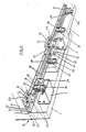
- FIGS. 1 and 2 the upper mechanisms of the fitting of the invention are shown. These mechanisms include rolling elements which consist of rollers or pulleys 3 with peripheral grooves, each of which is mounted on a support plate 4, as will be described below.
- rolling elements consist of rollers or pulleys 3 with peripheral grooves, each of which is mounted on a support plate 4, as will be described below.
- On the rear surface of the innermost panel 2 are directly fixed two rollers 3 by means of their plates 4.
- the rollers 3 can move on tracks formed by two rails 6 which are fixed to the external surface of the ceiling 7 of the empty space to be closed.
- These rails consist of an L-shaped profile which includes a flat branch 8 provided with orifices for the passage of fixing screws 9.
- the other branch 10 of these profiles is of larger size and has a rounded cross section , of radius approximately similar to or slightly less than that of the groove of the rollers 3.
- these sections 6 have on the branch 10 and from the external surface of the branch 8 a channel 11 on which a straightening core and connecting successive sections.
- the outermost rail 10 remains located adjacent to the free edge of the ceiling 7.
- the rollers or pulleys 3 are mounted on the support plate 4 by means of a bearing 13.
- the plate 4 has, on its rear surface, d 'a projection or pivot 14 and at one and the other end thereof, at different distance, from two grooves 15 and 16 of different length, of arcuate layout with center on the pivot 14.
- the pivot 14 is introduced into an orifice made in the panel 2 or on the bridges 5.
- the plate 4 is fixed by means of screws introduced through the grooves 15 and 16, their position and height being adjustable by turning it on the pivot 14, thanks to the size of the grooves 15 and 16.
- the screws 17, FIG. 1 are tightened to fix the plate 4 to the panel 2 and bridges 5.
- One of the rollers of each panel in this case one of the rollers 3 fixed to one of the bridges 5 and in the other one of the rollers 3 fixed to the panel 2, have, as an extension of its axis, a projection 18, which will serve to ensure the limit position for opening and closing the door panels.
- the bridges 5 are composed of folded U-shaped plates, which are fixed by one of their lateral branches to the internal surface of the door 5, while on the other lateral branch, the plates 4 carrying the rollers are fixed. 3.
- pivots 19 can protrude which are introduced in practical orifices from the internal surface of said panel 1, to serve as positioning elements to facilitate the mounting of the bridges.
- This mechanism includes two guides 20 parallel and close to each other, which are fixed to the bottom surface of the bottom 21 of the void to be closed.
- the outermost guide is placed in position adjacent to the free edge of the bottom 21.
- These guides are made up of L-shaped profiles, one of the branches of which, bearing the number 22, is completely flat and is attached to the outer surface of the bottom 21, to which it is fixed by means of screws 22 which pass through holes made on said branch.
- the other branch 23 of these profiles at its starting point a widening 24 on which a channel 25 is formed which opens onto the external surface of the branch 22, to introduce rectifier and connection guides, as in the case of the rails 6
- buffers 12 As in the case of Figures 1 and 2, between the guides 20 there are buffers 12 of similar constitution, which will serve to limit the maximum opening and closing position.
- the pads 26, as can be clearly seen in Figure 7, consist of an anchor core 27 and a body 28 with a profile that can be assembled to the branch 23 of the guides 20.
- a shoe of each panel further includes a stopper 29, which limits the opening and closing of the panels.
- the core 27 is fixed to the bridges 5 and to the panel 2 by means of screws 30, FIG. 7, while the body 28 is mounted on the core 27 by sliding.
- the screws 30 also serve for fixing the stopper 29, formed by a flat iron forming a right angle.
- the housing of the body 28, for its coupling to the core 27, is limited, as can be appreciated very well in FIG. 8, by flexible tongues 31, directed one towards each side, which are completed at their extremity in half arrowhead and which will serve as buffers to prevent relative sliding between the core 27 and the body 28, once the two parts are coupled.
- the buffers 12, as can be appreciated very well in FIGS. 1 and 6, are each formed by an anchoring base 32, which is fixed directly to the external surface of the ceiling 7 and bottom 21, in position adjacent to the rails 6 and guides 20, by a vertical plate 33 of adjustable position, and by a union angle 32a.
- the anchoring base 32 is formed by an L-shaped section piece, the branches of which have a different length.
- the longest branch 35 has holes 36 for the passage of the fixing screws to the external surface of the ceiling and bottom.
- the other branch, bearing the number 37, has vertical ridges 38 on its outer surface, as well as two horizontal grooves 39.
- the vertical plate 33 has on one of its sur faces of a groove 40 which can be assembled on the groove 38 of the anchoring base 32.
- This plate has more than two orifices 41 for the passage of fixing screws to the anchoring base.
- the union angle 32a mates on the concave surface of the anchoring base 32 and has threaded orifices to receive screws introduced through the holes 39 of the anchoring base 32 and orifices 41 of the plate 33, for their mutual union.
- the position of the plate 33 can be adjusted relative to the anchoring base 32, this being due to the grooves 39 of the anchoring base, the plate remaining locked by tightening the fixing screws to said base, by means of the ridges 38 and 40 opposables of the base and plate.
- the plate 33 has, from its vertical edges, notches 43 which remain superiorly limited by elastically deformable fasteners 45, which have transverse deviations on the end portion which determine an armrest angular 46, with the convexity directed towards the notch 43, partially closing it, to define the means for retaining the upper rollers.
- the fasteners 45 terminate on an end section 47 directed in an upward direction.
- the displacement of the panels 1 and 2 of the door is very easily obtained, this being due to the upper rolling elements and to the pads and lower guides.
- the weight of the door panels is supported by the ceiling 7 of the empty space to be closed.
- the opening and closing limit positions remain perfectly defined by means of the stops 12.
- the body 28 of the pads has externally on its upper and lower edges each of the grooves 48 and 49 of different depth, determined by the different height of the walls 50 which limit said grooves .
- This causes the mouth of one and the other channel and the edge of the walls which limit these, to remain located at a different distance from the mean longitudinal plane of the skid and, consequently, from the axis of the fixing screw 30.
- This constitution makes it possible to absorb possible mounting errors, by placing the body 28 of the pads on the position shown in the drawing or in the inverted position.
- the description of the fitting was made in relation to a type of door, but it can also be used in the case of interior doors.
- the rail or rails 6 would be arranged on the lower part on the ground to support the weight of the door by means of the rolling elements 3, which would be fixed to its lower part, while the guides 20 would be fixed to the upper part opposite to the corresponding rails, to cooperate with the pads 26 which would be fixed to the inner upper part of the door.
Landscapes
- Engineering & Computer Science (AREA)
- Mechanical Engineering (AREA)
- Wing Frames And Configurations (AREA)
- Support Devices For Sliding Doors (AREA)
- Special Wing (AREA)
Abstract
Description
L'invention présente se réfère à un ferrure pour portes coulissantes, qui peut être appliqué à des portes coulissantes à un panneau ou avec plus de deux, chacun desquels disposant d'éléments de roulements supérieurs et de patins inférieurs, déplaçables sur des pistes fixes dotées de butoirs qui limitent le déplacement des panneaux.The present invention refers to a fitting for sliding doors, which can be applied to sliding doors with one panel or with more than two, each of which having elements of upper bearings and lower pads, movable on fixed tracks provided bumpers that limit the movement of the panels.
On connaît déjà des ferrures pour portes coulissantes, du type que l'on a indiqué, dans lesquels les pistes sur lesquelles se déplacent les éléments de roulement supérieurs sont constitués par des profilés qui sont fixés sur la superficie interne du plafond de l'espace vide que les porte ferme. Quand les portes incluent deux panneaux, il est nécessaire de disposer deux profilés parallèles, un pour chaque porte. Avec cette constitution traditionnelle, les portes restent suspendues du profilé, devant supporter tout le poids de la porte. Avec l'usage, les vis et les éléments de fixation des profilés cités ont l'habitude de se desserrer, ce qui fait que le profilé perde son horizontalité, donnant lieu à un fonctionnement défectueux qui peut arriver à provoquer des coincements et des blocages des portes, du bruit lors de leur déplacement, etc...Fittings for sliding doors are already known, of the type indicated, in which the tracks on which the upper rolling elements move consist of profiles which are fixed to the internal surface of the ceiling of the empty space. that the door closes. When the doors include two panels, it is necessary to have two parallel profiles, one for each door. With this traditional constitution, the doors remain suspended from the profile, having to support the entire weight of the door. With use, the screws and the fastening elements of the mentioned profiles are used to loosen, which causes the profile to lose its horizontality, giving rise to a faulty operation which can cause jamming and blocking of the doors, noise when moving, etc ...
De plus, le montage des profilés et des panneaux des portes est normalement assez compliqué.In addition, the mounting of door profiles and panels is normally quite complicated.
L'objet de la présente invention est de développer un ferrage qui permette un montage simple aussi bien de ses composants que des panneaux des portes.The object of the present invention is to develop a fitting which allows simple assembly both of its components and of the door panels.
Un autre objet de l'invention est d'obtenir un ferrage avec lequel on obtienne un déplacement doux des panneaux et silencieux et de plus sans risque qu'il se produise des désalignements ou des dénivellements de ses composants, en assurant de cette façon un fonctionnement parfait de l'ensemble.Another object of the invention is to obtain a fitting with which a smooth displacement of the panels is obtained and silent and moreover without risk of misalignments or unevenness of its components, thereby ensuring operation perfect of the whole.
Le ferrure de l'invention permet de plus le montage de portes qui couvrent totalement le front de l'espace vide à fermer, du sol au plafond de la pièce ou de l'enceinte, en obtenant de meilleurs effets dans la finition et de l'aspect de ladite enceinte.The fitting of the invention also allows the mounting of doors which completely cover the front of the empty space to be closed, from floor to ceiling of the room or enclosure, obtaining better effects in the finishing and aspect of said enclosure.
Bien que le ferrure de l'invention puisse être utilisé pour des portes ayant un panneau, étant donné sa constitution et sa sécurité de fonctionement, il est d'application spécial pour les portes coulissantes ayant deux ou plus de deux panneaux.Although the fitting of the invention can be used for doors having a panel, given its constitution and its operational safety, it is of special application for sliding doors having two or more panels.
Dans le ferrure de l'invention, les pistes sur lesquelles se déplaceront les éléments de roulement et les patins sont constitués par un rail supérieur et un guide inférieur, si la porte n'a qu'un panneau, ou de deux rails supérieurs parallèles et proches entre eux et de deux guides inférieurs, aussi parallèles et proches entre eux, si la porte a 2 panneaux ou plus de deux. Dans l'un et l'autre cas, les rails et les guides sont disposés respectivement sur la surface externe du plafond et du fond du vide à fermer, le rail et le guide le plus externe restant situés en position adjacente au bord des superficies citées.In the fitting of the invention, the tracks on which the rolling elements and the pads will move consist of an upper rail and a lower guide, if the door has only one panel, or two parallel upper rails and close to each other and to two lower guides, also parallel and close to each other, if the door has 2 or more panels. In both cases, the rails and the guides are arranged respectively on the external surface of the ceiling and of the bottom of the void to be closed, the rail and the outermost guide remaining located in position adjacent to the edge of the areas mentioned. .
Les butoirs qui limitent le déplacement des panneaux de la porte comprennent une base d'ancrage, une plaque verticale et une cornière d'union. La base d'ancrage est fixée à la superficie externe du plafond et fond en position adjacente aux rails et guides. La plaque verticale est de position réglable, parallèle aux rails et aux guides, et est fixée sur la base d'ancrage, présentant, à partir de ses chants verticaux, des moyens de retenue des éléments de roulement et des butoirs pour les patins. La cornière d'union sert de base pour le filetage de vis de fixation de la plaque à la base d'ancrage.The bumpers that limit the movement of the door panels include an anchoring base, a vertical plate and a union angle. The anchoring base is fixed to the external surface of the ceiling and melts in position adjacent to the rails and guides. The vertical plate is of adjustable position, parallel to the rails and the guides, and is fixed to the anchoring base, having, from its vertical edges, means for retaining the rolling elements and buffers for the pads. The union angle serves as a base for threading the screws fixing the plate to the anchoring base.
Les éléments de roulement supérieurs se composent de galets à gorge périphérique, lesquels sont montés, moyennant des roulements, sur un axe qui est solidaire d'une plaque verticale et proche de ladite poulie. Cette plaque est fixée directement à la superficie interne du panneau de la porte le plus proche de l'espace vide à fermer, pour l'appui du galet sur le rail le plus externe, tandis que la fixation à la porte la plus éloignée du trou à fermer, la fixation est effectuée par l'intermédiaire d'un pont qui sauve le rail le plus externe et situe le galet sur le rail le plus interne ou éloigné de la porte.The upper rolling elements consist of rollers with peripheral grooves, which are mounted, by means of bearings, on an axis which is integral with a vertical plate and close to said pulley. This plate is fixed directly to the internal surface of the door panel closest to the empty space to be closed, for the support of the roller on the outermost rail, while the fixing to the door farthest from the hole to close, the fixing is carried out by means of a bridge which saves the outermost rail and locates the roller on the innermost rail or distant from the door.
Quant aux patins inférieurs, ils comprennent un noyau d'ancrage, un corps avec un profilé qui peut s'assembler au guide et au noyau d'ancrage, et un butoir limitateur d'ouverture. Le noyau d'ancrage est fixé directement à la superficie interne du panneau de la porte le plus proche de l'espace vide à fermer pour l'accouplement du corps cité au guide le plus externe, tandis que sa fixation à la porte la plus éloignée du vide à fermer est effectuée moyennant un pont qui situe le corps du patin sur le guide le plus interne ou éloigné des panneaux.As for the lower runners, they include an anchoring core, a body with a profile which can be assembled to the guide and the anchoring core, and an opening limiting stopper. The anchoring core is fixed directly to the internal surface of the door panel closest to the empty space to be closed for coupling the body cited to the outermost guide, while its fixing to the most distant door vacuum to be closed is effected by means of a bridge which locates the body of the skate on the innermost or distant guide from the panels.
Les butoirs du rail et guide externes sont disposés entre les profilés qui définissent les rails supérieurs et les deux guides inférieurs, tandis que les butoirs du rail et guide internes sont disposés sur le prolongement dudit rail et guide.The stops of the rail and external guide are arranged between the profiles which define the upper rails and the two lower guides, while the stops of the rail and internal guide are arranged on the extension of said rail and guide.
La base d'ancrage citée auparavant des butoirs, se compose d'une pièce de section en L, sur la superficie concave de laquelle on accouple la cornière d'union, de nature métallique. Cette pièce dispose sur la superficie externe d'une de ses branches de dents ou de stries transversales. Quant à la plaque verticale des butoirs, elle inclut une zone inférieure, dotée sur une de ses superficies de dents ou de stries verticales, et une zone supérieure qui présente, à partir de ses bords verticaux des échancrures opposées dotées de moyens de retenue des éléments de roulement. La plaque et la base d'ancrage sont fixées moyennant des vis qui sont vissées sur des orifices filetés de la cornière d'union, les dents de la plaque verticale restant adossées à celles de base d'ancrage, la position relative entre les deux éléments étant réglable grâce à ces dents.The anchoring base mentioned above of the bumpers, is composed of a piece of L-shaped section, on the concave surface of which the union angle, of metallic nature, is coupled. This part has on the outer surface of one of its branches of teeth or transverse ridges. As for the vertical plate of the bumpers, it includes a lower zone, provided on one of its surfaces with teeth or vertical ridges, and an upper zone which has, from its vertical edges, opposite notches provided with means for retaining the elements of rolling. The plate and the anchoring base are fixed by means of screws which are screwed onto threaded orifices of the union angle, the teeth of the vertical plate remaining attached to those of the anchoring base, the relative position between the two elements being adjustable thanks to these teeth.
L' axe de l'un des galets ou poulies supérieurs de chaque panneau dépasse de la superficie libre de celle-ci en une portion qui reste opposée aux échancrures de la plaque verticale des butoirs, de telle sorte que lorsque les panneaux se trouvent dans la position limite de fermeture ou d'ouverture, la portion qui dépasse déjà citée auparavant de l'axe des poulies est introduite dans les échancrures jusqu'à se situer derrière les moyens de retenue de celles-ci, où ils définissent des positions d'emboîtement, étant nécessaire d'exercer un léger effort pour obtenir la libération du prolongement de l'axe et pouvoir initier le déplacement du panneau.The axis of one of the upper rollers or pulleys of each panel protrudes from the free area thereof in a portion which remains opposite the notches in the vertical plate of the stops, so that when the panels are in the limit position for closing or opening, the portion which already protrudes above mentioned from the axis of the pulleys is introduced into the notches until it is located behind the retaining means of the latter, where they define nesting positions , being necessary to exert a slight effort to obtain the release of the extension of the axis and be able to initiate the movement of the panel.
Les caractéristiques exposées, ainsi que d'autres propres de l'invention, seront mises en évidence par la suite, en plus grand détail, se référant aux dessins adjoints, sur lesquels on montre un exemple de réalisation non limitatif.The characteristics set out, as well as others specific to the invention, will be highlighted later, in greater detail, with reference to the accompanying drawings, in which a non-limiting exemplary embodiment is shown.
Sur les dessins:
- La figure 1 est une perspective postérieure des éléments de roulement supérieurs du ferrage de l'invention.
- La figure 2 est une vue partiellement sectionnée d'après la direction A de la figure 1.
- Les figures 3 et 4 sont, respectivement, un tracé frontal et plan supérieur d'un des éléments de roulements supérieurs.
- La figure 5 est une section d'après la ligne de coupe V-V de la figure 3.
- La figure 6 est une perspective postérieure des patins et pistes inférieurs.
- La figure 7 est une vue, partiellement sectionnée, d'après la direction B de la figure 6.
- La figure 8 est un levé intérieur du corps des patins.
- La figure 9 est un tracé frontal de la base d'ancrage des butoirs.
- La figure 10 est une section d'après la ligne de coupe X-X de la figure 9.
- La figure 11 est une vue de profil de la base d'ancrage de la figure 9.
- La figure 12 est un tracé frontal de la plaque verticale des butoirs.
- La figure 13 est une section d'après la ligne de cou pe XIII-XIII de la figure 12.
- La figure 14 est une section d'après la ligne de coupe XIV-XIV de la figure 12.
- Figure 1 is a rear perspective of the upper rolling elements of the fitting of the invention.
- FIG. 2 is a view partially sectioned along the direction A of FIG. 1.
- Figures 3 and 4 are, respectively, a front and top plan of one of the upper bearing elements.
- FIG. 5 is a section according to the section line VV of FIG. 3.
- Figure 6 is a rear perspective of the pads and lower tracks.
- FIG. 7 is a view, partially sectioned, along the direction B of FIG. 6.
- Figure 8 is an inside survey of the skate body.
- Figure 9 is a front view of the anchor base of the bumpers.
- FIG. 10 is a section along the section line XX of FIG. 9.
- FIG. 11 is a side view of the anchoring base of FIG. 9.
- Figure 12 is a front view of the vertical plate of the buffers.
- Figure 13 is a section from the neck line pe XIII-XIII of figure 12.
- Figure 14 is a section along the section line XIV-XIV of Figure 12.
Dans l'exemple représenté sur les dessins la porte se compose de deux panneaux portant les numéros 1 et 2. Sur les figures 1 et 2 les mécanismes supérieurs du ferrage de l'invention sont représentés. Ces mécanismes incluent des éléments de roulement qui sont constitués de galets ou poulies 3 à gorge périphérique, chacun d'eux est monté sur une plaque support 4, tel qu'on le décrira par la suite. Sur la superficie postérieure du panneau le plus interne 2 sont fixés directement deux galets 3 par l'intermédiaire de leurs plaques 4. Sur le panneau 1 le plus externe ou séparé du vide à fermer deux autres galets sont montés 3, par l'intermédiaire de ponts 5.In the example shown in the drawings, the door consists of two panels bearing the
Les galets 3 peuvent se déplacer sur des pistes constituées par deux rails 6 qui sont fixés à la superficie externe du plafond 7 de l'espace vide à fermer. Ces rails se composent d'un profilé en L qui inclut une branche plane 8 dotée d'orifices pour le passage de vis de fixation 9. L'autre branche 10 de ces profilés sont d'une plus grande grosseur et présentent une section transversale arrondie, de rayon approximativement semblable ou légèrement inférieur à celui de la gorge des galets 3. De plus, ces profilés 6 disposent sur la branche 10 et à partir de la surface externe de la branche 8 d'un canal 11 sur lequel on peut disposer une âme redresseuse et de connexion de tronçons successifs.The
Le rail le plus externe 10 reste situé en position adjacente au bord libre du plafond 7.The
Pour limiter le déplacement des panneaux 1 et 2, on dispose des butoirs 12, deux de ces derniers situés sur les rails 6 et deux autres immédiatement à la suite du rail 6 postérieur.To limit the movement of the
Tel que l'on peut mieux l'apprécier sur les figures 3 à 5, les galets ou poulies 3 sont montés sur la plaque support 4 par l'intermédiaire d'un roulement 13. La plaque 4 dispose, sur sa surface postérieure, d'une saillie ou pivot 14 et à l'un et l'autre extrémité de celui-ci, à différente distance, de deux rainures 15 et 16 de différente longueur, de tracé arqué avec centre sur le pivot 14. Pour le montage de ces galets on introduit le pivot 14 dans un orifice pratiqué dans le panneau 2 ou sur les ponts 5. Ensuite la plaque 4 est fixée moyennant des vis introduites au travers des rainures 15 et 16, leur position et hauteur pouvant être réglées en la faisant tourner sur le pivot 14, grâce à la dimension des rainures 15 et 16. Une fois dûment placée la poulie 3, on serre les vis 17, figure 1,de fixation de la plaque 4 au panneau 2 et ponts 5.As can be better appreciated in Figures 3 to 5, the rollers or
Un des galets de chaque panneau, dans ce cas un des galets 3 fixé à un des ponts 5 et dans l'autre un des galets 3 fixé au panneau 2, disposent, comme prolongement de son axe, d'une saillie 18, qui servira pour assurer la position limite d'ouverture et de fermeture des panneaux de la porte.One of the rollers of each panel, in this case one of the
Les ponts 5 sont composés de plaques pliées en forme de U, qui sont fixés par l'une de leurs branches latérales à la surface interne de la porte 5, tandis que sur l'autre branche latérale, on fixe les plaques 4 portant les galets 3. Comme on peut le voir sur la figure 2, de la branche qui est fixée au panneau 1, des pivots 19 peuvent dépasser qui sont introduits dans des orifices pratiques à partir de la surface interne dudit panneau 1, pour servir d'éléments positionneurs pour faciliter le montage des ponts.The
Sur la partie inférieure de la porte, un mécanisme est disposé et il est représenté sur les figures 6 et 7. Ce mécanisme inclut deux guides 20 parallèles et proches entre eux, qui sont fixés à la surface inférieure du fond 21 du vide à fermer. Le guide le plus externe est disposé en position adjacente au bord libre du fond 21. Ces guides sont composés de profilés en L, une des branches duquel, portant le numéro 22, est totalement plane et est adossée à la surface externe du fond 21, auquel elle est fixée moyennant des vis 22 qui passent par des trous pratiqués sur ladite branche. L'autre branche 23 de ces profilés en son point de départ un élargissement 24 sur lequel est formé un canal 25 qui débouche sur la superficie externe de la branche 22, pour introduire des guides redresseurs et de connexion, comme dans le cas des rails 6. La branche 23, à partir de son chant longitudinal libre, définit les guides sur lesquels glissent les patins 26, deux desquels sont fixés directement à la surface interne du panneau 2 le plus interne, tandis qu'au panneau externe 1 on fixe deux autres patins par l'intermédiaire de ponts 5 semblables à ceux décrits pour les éléments de roulement sur les figures 1 et 2.On the lower part of the door, a mechanism is arranged and it is shown in Figures 6 and 7. This mechanism includes two
De même que dans le cas des figures 1 et 2, entre les guides 20 on dispose des butoirs 12 de constitution semblable, qui serviront à limiter la position d'ouverture et de fermeture maximum.As in the case of Figures 1 and 2, between the
Les patins 26, comme on peut très bien le voir sur la figure 7, se compsoent d'un noyau d' ancrage 27 et d'un corps 28 avec un profilé assemblable à la branche 23 des guides 20. Un patin de chaque panneau inclut de plus un butoir 29, qui limite l'ouverture et la fermeture des panneaux. Le noyau 27 est fixé aux ponts 5 et au panneau 2 moyennant des vis 30, figure 7, tandis que le corps 28 est monté sur le noyau 27 par glissement. Les vis 30 servent de plus pour la fixation du butoir 29, formé par un fer plat formant un angle droit.The
Le boîtier du corps 28, pour son accouplement sur le noyau 27, est limité, tel que l'on peut très bien apprécier sur la figure 8, par des languettes 31 flexibles, dirigées l'une vers chaque côté, qui sont achevées à leur extrémite en demi-pointe de flèche et qui serviront de butoirs pour empêcher le glissement relatif entre le noyau 27 et le corps 28, une fois les deux pièces accouplées.The housing of the
Les butoirs 12, comme on peut très bien l'apprécier sur les figures 1 et 6, sont formés chacun par une base d'ancrage 32, qui est fixée directement à la surface externe du plafond 7 et fond 21, en position adjacente aux rails 6 et guides 20, par une plaque verticale 33 de position réglable, et par une cornière d'union 32a.The
La base d'ancrage 32, comme on peut le voir sur les figures 9 et 11, est formée par une pièce de section en L, dont les branches ont une longueur différente. La branche la plus longue 35 dispose de trous 36 pour le passage des vis de fixage à la superficie externe du plafond et fond. L'autre branche, portant le numéro 37, dispose sur sa surface externe des stries verticales 38, ainsi que de deux rainures horizontales 39.The anchoring
La plaque verticale 33, comme on peut très bien l'apprécier sur les figures 12 à 14, dispose sur une de ses sur faces d'une striure 40 qui peut s'assembler sur la striure 38 de la base d'ancrage 32. Cette plaque dispose de plus de deux orifices 41 pour le passage de vis de fixage à la base d'ancrage.The
La cornière d'union 32a, de nature métallique, s'accouple sur la superficie concave de la base d'ancrage 32 et dispose d'orifices filetés pour recevoir des vis introduites au travers des trous 39 de la base d'ancrage 32 et des orifices 41 de la plaque 33, pour leur union mutuelle.The
La position de la plaque 33 peut être réglée par rapport à la base d'ancrage 32, ceci étant du aux rainures 39 de la base d'ancrage, la plaque restant bloquée en serrant les vis de fixage à ladite base, grâce aux stries 38 et 40 opposables de la base et plaque.The position of the
Comme on peut le voir sur la figure 12, la plaque 33 dispose, à partir de ses chants verticaux, des échancrures 43 qui restent supérieurement limitées par des attaches 45 élastiquement déformables, lesquelles disposent sur la portion extrême d'écarts transversaux qui déterminent un accoudement angulaire 46, avec la convexité dirigée vers l'échancrure 43, la fermant partiellement, pour définir les moyens de retenue des galets supérieurs. Les attaches 45 terminent sur un tronçon extrême 47 dirigé en sens ascendant.As can be seen in FIG. 12, the
Revenons à la figure 1, quand les panneaux 1 et 2 arrivent à leurs positions limites d'ouverture ou de fermeture, la saillie 18 des galets 3 est introduit dans l'échancrure 43 du butoir 12 opposé, jusqu'à ce qu'elle soit retenue par l'accoudement angulaire 46. En même temps, comme on peut le voir sur la figure 6, où le panneau 2 de la porte est représenté en position limite de fermeture, le butoir 29 se heurte au chant opposé de la plaque 33, arrivant la même chose dans la position limite d'ouverture. De cette façon, les panneaux restent retenus dans leur position limite d'ouverture et de fermeture. Pour les libérer de cette position, il suffit d'exercer une légère poussée sur les panneaux pour obtenir que le prolongement 18 de l'axe des galets supérieurs sauve l'accoudement angulaire 46 qui ferme partiellement l'échancrure 43.Returning to FIG. 1, when the
Avec la constitution décrite , le déplacement des panneaux 1 et 2 de la porte est obtenu très facilement, ceci étant dû aux éléments de roulement supérieurs et aux patins et guides inférieurs. Le poids des panneaux de la porte est supporté par le plafond 7 de l'espace vide à fermer. Les positions limites d'ouverture et de fermeture restent parfaitement définies moyennant les butoirs 12.With the constitution described, the displacement of the
Le montage des différents composants, ainsi que celui des panneaux 1 et 2 peut être exécuté très facilement, grâce à la possibilité de réglage de hauteur des plaques 4 qui portent les galets 3.The assembly of the various components, as well as that of the
De plus, tel qu'on peut le voir sur la figure 7, le corps 28 des patins dispose extérieurement sur ses chants supérieur et inférieur chacun des rainures 48 et 49 de différente profondeur, déterminée par la hauteur différente des parois 50 qui limitent lesdites rainures. Ceci fait que l'embouchure de l'un et de l'autre canal et le chant des parois qui limitent ceux-ci, restent situés à une distance différente du plan longitudinal moyen du patin et, par conséquent, de l'axe de la vis de fixation 30. Cette constitution permet d'absorber de possibles erreurs de montage, en plaçant le corps 28 des patins sur la position montrée sur le dessin ou en position invertie.In addition, as can be seen in Figure 7, the
Tel qu'on l'a indiqué au début du mémoire, la description de la ferrure été faite en rapport avec un type de porte, mais elle peut aussi être utilisée dans le cas de portes intérieures. Dans ce cas, le rail ou les rails 6 seraient disposés sur la partie inférieure sur le sol pour supporter le poids de la porte moyennant les éléments de roulement 3, qui seraient fixés à sa partie inférieure, tandis que les guides 20 seraient fixés à la partie supérieure opposés aux rails correspondants, pour coopérer avec les patins 26 qui seraient fixés à la partie supérieure intérieure de la porte.As indicated at the beginning of the memoir, the description of the fitting was made in relation to a type of door, but it can also be used in the case of interior doors. In this case, the rail or rails 6 would be arranged on the lower part on the ground to support the weight of the door by means of the rolling
Suffisamment décrite la nature de l'invention, ainsi que la manière de la réaliser dans la pratique, il faut faire figurer que les dispositions indiquées antérieurement sont susceptibles de modifications de détail mais sans changer son principe fondamental.Sufficiently described the nature of the invention, as well as the manner of carrying it out in practice, it should be noted that the provisions indicated previously are susceptible of modifications of detail but without changing its fundamental principle.
Claims (10)
Priority Applications (1)
| Application Number | Priority Date | Filing Date | Title |
|---|---|---|---|
| AT89500083T ATE99021T1 (en) | 1989-02-27 | 1989-08-02 | FITTING FOR SLIDING DOORS. |
Applications Claiming Priority (2)
| Application Number | Priority Date | Filing Date | Title |
|---|---|---|---|
| ES8900703 | 1989-02-27 | ||
| ES8900703A ES2012667A6 (en) | 1989-02-27 | 1989-02-27 | Mounting for sliding doors. |
Publications (2)
| Publication Number | Publication Date |
|---|---|
| EP0385045A1 true EP0385045A1 (en) | 1990-09-05 |
| EP0385045B1 EP0385045B1 (en) | 1993-12-22 |
Family
ID=8260650
Family Applications (1)
| Application Number | Title | Priority Date | Filing Date |
|---|---|---|---|
| EP89500083A Expired - Lifetime EP0385045B1 (en) | 1989-02-27 | 1989-08-02 | Mounting for sliding doors |
Country Status (5)
| Country | Link |
|---|---|
| EP (1) | EP0385045B1 (en) |
| JP (1) | JPH0730650B2 (en) |
| AT (1) | ATE99021T1 (en) |
| DE (1) | DE68911670T2 (en) |
| ES (1) | ES2012667A6 (en) |
Cited By (9)
| Publication number | Priority date | Publication date | Assignee | Title |
|---|---|---|---|---|
| EP0502285A1 (en) * | 1991-03-05 | 1992-09-09 | Klein Iberica, S.A. | Mechanism for the mounting of sliding doors |
| EP0626495A1 (en) * | 1993-03-26 | 1994-11-30 | Klein Iberica, S.A. | Mechanism for sliding glass doors |
| EP1028214A2 (en) * | 1999-02-09 | 2000-08-16 | Bauelemente Kontakt GmbH & Co. Kg | Sliding door system |
| WO2008031472A1 (en) * | 2006-09-15 | 2008-03-20 | Hermann Francksen Nachf. Gmbh & Co. Kg | Device for the displaceable arrangement of a sliding door |
| WO2008028945A3 (en) * | 2006-09-06 | 2008-09-25 | Liexco Sa | Modular rail system for suspending sliding doors and sliding door system with user accessible braking / stopping element |
| EP2098669A1 (en) | 2008-03-03 | 2009-09-09 | Edac | Guiding device for pocket door |
| CN102383672A (en) * | 2011-07-18 | 2012-03-21 | 佛山市顺德暨德科技有限公司 | Double-lock lockset with fingerprint recognition function |
| EP2336468A3 (en) * | 2009-12-18 | 2014-05-28 | Hettich-Heinze GmbH & Co. KG | Fitting for two sliding door leaves |
| PL126754U1 (en) * | 2017-11-03 | 2019-05-06 | Valcomp Spolka Z Ograniczona Odpowiedzialnoscia | Sliding shock-absorbing stopper |
Families Citing this family (7)
| Publication number | Priority date | Publication date | Assignee | Title |
|---|---|---|---|---|
| JP2549759B2 (en) * | 1990-10-30 | 1996-10-30 | 松下電工株式会社 | Door opener |
| JP3008316U (en) * | 1994-03-22 | 1995-03-14 | 株式会社末廣産業 | Height adjustable roller |
| KR200460854Y1 (en) * | 2008-08-29 | 2012-06-11 | 주식회사 바로크주방가구 | Door stopper of a kitchen furniture |
| KR200465354Y1 (en) * | 2012-05-11 | 2013-02-14 | 권오성 | Guide-stopping apparatus for sliding doors of drawer |
| CA2964538C (en) * | 2016-04-13 | 2018-05-15 | 1925Workbench Ltd. | Rail-mounted doors |
| RU207309U1 (en) * | 2021-04-28 | 2021-10-21 | Данил Юрьевич Онищенко | STOP |
| KR102537718B1 (en) * | 2022-07-11 | 2023-05-31 | 주식회사 비쓰리이앤에스 | Cylinderical hyperbaric oxygen chamber with curved sliding door |
Citations (5)
| Publication number | Priority date | Publication date | Assignee | Title |
|---|---|---|---|---|
| US3159866A (en) * | 1962-05-31 | 1964-12-08 | Acme Appliance Mfg Company | Vertically adjustable sliding door hanger |
| DE2614810A1 (en) * | 1976-04-06 | 1977-10-20 | Heinze Fa R | Retainer and guide for furniture sliding doors - has vertical shafts for guide rollers and adjusting retainer bracket |
| EP0010220A1 (en) * | 1978-10-12 | 1980-04-30 | Inbauproduct Inter-IP AG | Cabinet with sliding doors |
| US4322914A (en) * | 1979-11-20 | 1982-04-06 | State Wide Aluminum Of Indiana, Inc. | Slideable closure construction |
| GB2164691A (en) * | 1984-09-20 | 1986-03-26 | Kermi Gmbh | Sliding-door partition for a shower |
-
1989
- 1989-02-27 ES ES8900703A patent/ES2012667A6/en not_active Expired - Fee Related
- 1989-08-02 AT AT89500083T patent/ATE99021T1/en not_active IP Right Cessation
- 1989-08-02 DE DE68911670T patent/DE68911670T2/en not_active Expired - Lifetime
- 1989-08-02 EP EP89500083A patent/EP0385045B1/en not_active Expired - Lifetime
- 1989-10-17 JP JP1270144A patent/JPH0730650B2/en not_active Expired - Lifetime
Patent Citations (5)
| Publication number | Priority date | Publication date | Assignee | Title |
|---|---|---|---|---|
| US3159866A (en) * | 1962-05-31 | 1964-12-08 | Acme Appliance Mfg Company | Vertically adjustable sliding door hanger |
| DE2614810A1 (en) * | 1976-04-06 | 1977-10-20 | Heinze Fa R | Retainer and guide for furniture sliding doors - has vertical shafts for guide rollers and adjusting retainer bracket |
| EP0010220A1 (en) * | 1978-10-12 | 1980-04-30 | Inbauproduct Inter-IP AG | Cabinet with sliding doors |
| US4322914A (en) * | 1979-11-20 | 1982-04-06 | State Wide Aluminum Of Indiana, Inc. | Slideable closure construction |
| GB2164691A (en) * | 1984-09-20 | 1986-03-26 | Kermi Gmbh | Sliding-door partition for a shower |
Cited By (13)
| Publication number | Priority date | Publication date | Assignee | Title |
|---|---|---|---|---|
| EP0502285A1 (en) * | 1991-03-05 | 1992-09-09 | Klein Iberica, S.A. | Mechanism for the mounting of sliding doors |
| EP0626495A1 (en) * | 1993-03-26 | 1994-11-30 | Klein Iberica, S.A. | Mechanism for sliding glass doors |
| US5450693A (en) * | 1993-03-26 | 1995-09-19 | Klein Iberica S.A | Mechanism for sliding glass doors |
| EP1028214A2 (en) * | 1999-02-09 | 2000-08-16 | Bauelemente Kontakt GmbH & Co. Kg | Sliding door system |
| EP1028214A3 (en) * | 1999-02-09 | 2003-05-28 | Bauelemente Kontakt GmbH & Co. Kg | Sliding door system |
| WO2008028945A3 (en) * | 2006-09-06 | 2008-09-25 | Liexco Sa | Modular rail system for suspending sliding doors and sliding door system with user accessible braking / stopping element |
| US9003713B2 (en) | 2006-09-06 | 2015-04-14 | Rubelko | Modular rail system for suspending sliding doors and sliding door system with user accessible braking/stopping element |
| WO2008031472A1 (en) * | 2006-09-15 | 2008-03-20 | Hermann Francksen Nachf. Gmbh & Co. Kg | Device for the displaceable arrangement of a sliding door |
| EP2098669A1 (en) | 2008-03-03 | 2009-09-09 | Edac | Guiding device for pocket door |
| EP2336468A3 (en) * | 2009-12-18 | 2014-05-28 | Hettich-Heinze GmbH & Co. KG | Fitting for two sliding door leaves |
| CN102383672A (en) * | 2011-07-18 | 2012-03-21 | 佛山市顺德暨德科技有限公司 | Double-lock lockset with fingerprint recognition function |
| CN102383672B (en) * | 2011-07-18 | 2013-07-17 | 佛山市顺德暨德科技有限公司 | Double-lock lockset with fingerprint recognition function |
| PL126754U1 (en) * | 2017-11-03 | 2019-05-06 | Valcomp Spolka Z Ograniczona Odpowiedzialnoscia | Sliding shock-absorbing stopper |
Also Published As
| Publication number | Publication date |
|---|---|
| JPH0730650B2 (en) | 1995-04-10 |
| DE68911670D1 (en) | 1994-02-03 |
| JPH02229381A (en) | 1990-09-12 |
| EP0385045B1 (en) | 1993-12-22 |
| ATE99021T1 (en) | 1994-01-15 |
| DE68911670T2 (en) | 1994-07-07 |
| ES2012667A6 (en) | 1990-04-01 |
Similar Documents
| Publication | Publication Date | Title |
|---|---|---|
| EP0385045A1 (en) | Mounting for sliding doors | |
| FR3005481A3 (en) | DOOR ASSEMBLY | |
| CA2517696A1 (en) | Device for fixing a wire on a load bearing element provided with at least two openings | |
| EP0195721A1 (en) | Device for preventing disengagement of sliding doors | |
| FR2706524A1 (en) | Device for closing the lateral ends of roller shutter boxes. | |
| CA2483088A1 (en) | Angle accessory for chutes with two skewed assembled panels | |
| EP2098669B1 (en) | Guiding device for pocket door | |
| EP1524399B1 (en) | Security barrier | |
| FR2988110A1 (en) | Locking system for slab utilized for forming ceiling or partition, has recall units including ferromagnetic part, and elastic unit that positions recall units in blocking position for maintaining finger in unlocked position | |
| FR2514812A1 (en) | FIXING GUIDE AND FIXING SYSTEM | |
| EP0456525B1 (en) | Adjustable mounting device for leaf of elevator cabin door | |
| FR2519052A1 (en) | BALUSTRADE IN ADJUSTABLE PREFABRICATED ELEMENTS FOR PROTECTION AND DELIMITATION OF PLANED AND INCLINED SURFACES | |
| FR2887283A1 (en) | Garage door`s panel assembly protecting device, has elements with lateral flanges contacting lateral sides of panels, where one of flanges carries lug, with wing, laterally extended along another flange and determining surface | |
| BE1029205B1 (en) | Metallic bonding medium | |
| FR2649138A1 (en) | DEVICE FOR ELASTICALLY FIXING A RAILWAY RAIL ON ITS SUPPORT | |
| FR2597532A1 (en) | DEVICE FOR FIXING WALL AND CEILING COATING PANELS | |
| FR2693095A1 (en) | Pivoting screen for shower tray or bath - having panel with frame whose uprights are sections to which mobile piece is fixed that slides in pivoting section fixed to wall | |
| FR2749497A1 (en) | FIXING ASSEMBLY FOR PARTS OF A SHOWER CABIN | |
| EP1306498A1 (en) | Mounting device for panels, in particular for veranda roof panels and veranda with such a device | |
| FR2897097A1 (en) | Sliding gate or door has upper guide rail shaped to co-operate with at least one vertical roller | |
| FR2569102A1 (en) | Sliding door system for shower cubicle | |
| FR2459864A1 (en) | WINDOW, DOOR, OR OTHER JOINERY WITH SLIDING DOOR, COMPRISING A DEVICE FOR LOCKING TWO AMOUNTS | |
| FR2745601A1 (en) | Sliding door | |
| FR2759407A1 (en) | TOP GUIDE FOR SLIDING DOOR | |
| FR2718630A1 (en) | Wall for shower cubicles or bath. |
Legal Events
| Date | Code | Title | Description |
|---|---|---|---|
| PUAI | Public reference made under article 153(3) epc to a published international application that has entered the european phase |
Free format text: ORIGINAL CODE: 0009012 |
|
| AK | Designated contracting states |
Kind code of ref document: A1 Designated state(s): AT BE CH DE FR GB IT LI NL SE |
|
| 17P | Request for examination filed |
Effective date: 19901129 |
|
| 17Q | First examination report despatched |
Effective date: 19921005 |
|
| GRAA | (expected) grant |
Free format text: ORIGINAL CODE: 0009210 |
|
| AK | Designated contracting states |
Kind code of ref document: B1 Designated state(s): AT BE CH DE FR GB IT LI NL SE |
|
| REF | Corresponds to: |
Ref document number: 99021 Country of ref document: AT Date of ref document: 19940115 Kind code of ref document: T |
|
| REF | Corresponds to: |
Ref document number: 68911670 Country of ref document: DE Date of ref document: 19940203 |
|
| ITF | It: translation for a ep patent filed |
Owner name: STUDIO TORTA SOCIETA' SEMPLICE |
|
| GBT | Gb: translation of ep patent filed (gb section 77(6)(a)/1977) |
Effective date: 19940318 |
|
| PLBE | No opposition filed within time limit |
Free format text: ORIGINAL CODE: 0009261 |
|
| STAA | Information on the status of an ep patent application or granted ep patent |
Free format text: STATUS: NO OPPOSITION FILED WITHIN TIME LIMIT |
|
| 26N | No opposition filed | ||
| EAL | Se: european patent in force in sweden |
Ref document number: 89500083.4 |
|
| REG | Reference to a national code |
Ref country code: GB Ref legal event code: IF02 |
|
| PGFP | Annual fee paid to national office [announced via postgrant information from national office to epo] |
Ref country code: NL Payment date: 20080831 Year of fee payment: 20 Ref country code: CH Payment date: 20080905 Year of fee payment: 20 |
|
| PGFP | Annual fee paid to national office [announced via postgrant information from national office to epo] |
Ref country code: AT Payment date: 20080805 Year of fee payment: 20 Ref country code: IT Payment date: 20080825 Year of fee payment: 20 Ref country code: FR Payment date: 20080724 Year of fee payment: 20 |
|
| PGFP | Annual fee paid to national office [announced via postgrant information from national office to epo] |
Ref country code: GB Payment date: 20080827 Year of fee payment: 20 |
|
| PGFP | Annual fee paid to national office [announced via postgrant information from national office to epo] |
Ref country code: DE Payment date: 20081007 Year of fee payment: 20 |
|
| PGFP | Annual fee paid to national office [announced via postgrant information from national office to epo] |
Ref country code: SE Payment date: 20080818 Year of fee payment: 20 Ref country code: BE Payment date: 20080813 Year of fee payment: 20 |
|
| REG | Reference to a national code |
Ref country code: CH Ref legal event code: PL |
|
| REG | Reference to a national code |
Ref country code: GB Ref legal event code: PE20 Expiry date: 20090801 |
|
| BE20 | Be: patent expired |
Owner name: S.A. *KLEIN IBERICA Effective date: 20090802 |
|
| NLV7 | Nl: ceased due to reaching the maximum lifetime of a patent |
Effective date: 20090802 |
|
| EUG | Se: european patent has lapsed | ||
| PG25 | Lapsed in a contracting state [announced via postgrant information from national office to epo] |
Ref country code: NL Free format text: LAPSE BECAUSE OF EXPIRATION OF PROTECTION Effective date: 20090802 Ref country code: GB Free format text: LAPSE BECAUSE OF EXPIRATION OF PROTECTION Effective date: 20090801 |