EP0501603A2 - Tête magnétique à film mince - Google Patents
Tête magnétique à film mince Download PDFInfo
- Publication number
- EP0501603A2 EP0501603A2 EP92300382A EP92300382A EP0501603A2 EP 0501603 A2 EP0501603 A2 EP 0501603A2 EP 92300382 A EP92300382 A EP 92300382A EP 92300382 A EP92300382 A EP 92300382A EP 0501603 A2 EP0501603 A2 EP 0501603A2
- Authority
- EP
- European Patent Office
- Prior art keywords
- thin film
- magnetic
- magnetic head
- flux
- film magnetic
- Prior art date
- Legal status (The legal status is an assumption and is not a legal conclusion. Google has not performed a legal analysis and makes no representation as to the accuracy of the status listed.)
- Granted
Links
Images


Classifications
-
- G—PHYSICS
- G11—INFORMATION STORAGE
- G11B—INFORMATION STORAGE BASED ON RELATIVE MOVEMENT BETWEEN RECORD CARRIER AND TRANSDUCER
- G11B5/00—Recording by magnetisation or demagnetisation of a record carrier; Reproducing by magnetic means; Record carriers therefor
- G11B5/127—Structure or manufacture of heads, e.g. inductive
- G11B5/33—Structure or manufacture of flux-sensitive heads, i.e. for reproduction only; Combination of such heads with means for recording or erasing only
- G11B5/39—Structure or manufacture of flux-sensitive heads, i.e. for reproduction only; Combination of such heads with means for recording or erasing only using magneto-resistive devices or effects
- G11B5/3903—Structure or manufacture of flux-sensitive heads, i.e. for reproduction only; Combination of such heads with means for recording or erasing only using magneto-resistive devices or effects using magnetic thin film layers or their effects, the films being part of integrated structures
- G11B5/3967—Composite structural arrangements of transducers, e.g. inductive write and magnetoresistive read
Definitions
- This invention relates to magnetic heads for writing on and reading from magnetic recording media and, more particularly, to thin film magnetic heads.
- Integrated head designs are also known in which the MR element is located away from the ABS.
- U.S. Patent 4,300,177 shows an integrated head in which the MR element is across a gap in one leg of the yoke (Fig. 1) or in a magnetic path across the yoke (Figs. 2 and 3).
- the prior art integrated thin film magnetic heads have not been designed with reluctances of various elements chosen so that both the read and write efficiencies are over fifty percent, the problem being that, if the MR element effectively shunts the transducing gap, the reluctance of the MR element must be low for good read efficiency and high for good write efficiency.
- a thin-film magnetic head for writing data to and reading data from a magnetic medium
- the head comprising a magnetic yoke structure having two limbs forming at one end confronting pole pieces having a write gap therebetween, each limb being wound with a coil so that the flux produced in each limb by equally energizing the coils is equal; and characterized by a flux guide interposed between said two limbs and extending from the transducing gap so that, when there is equal and opposite flux in the two limbs, there is substantially zero flux in the flux guide, the flux guide having an opening therein; and a magnetoresistive element coupled across the opening, whereby data recorded on a magnetic medium can be sensed by the magneto-resistive element.
- the magnetisation is rotated in the MR element in response to magnetic fields being read at the write gap.
- the present invention is described as embodied in a magnetic disk file as shown in Fig. 1.
- At least one rigid rotatable magnetic disk 11 is supported on a spindle and rotated by a disk drive motor (not shown).
- the magnetic recording media on each disk is in the form of an annular pattern of concentric data tracks d as shown on disk 11.
- Each slider 13 supports one or more read/write head 10 and is attached to an actuator arm 15 by means of a suspension 17.
- the suspension 17 provides a slight spring force which biases the slider 13 against the disk surface.
- Each actuator arm 15 is attached to actuator means 19.
- the actuator means 19 shown schematically in Fig. 1 is a rotary actuator which is operable to move actuator arm 15 in a controlled manner about pivot point 21 as known in the art so that slider 13 and the associated read/write head 10 can be moved to a chosen one of the data tracks on magnetic recording medium 11.
- the rotation of the disk generates an air bearing between the slider 13 and the disk surface.
- the air bearing thus counterbalances the slight spring force of the suspension and supports the slider 13 off the disk surface during operation.
- disk files may contain a large number of disks and actuators, and that each actuator may support a number of sliders.
- the thin film magnetic head 10 comprises a first pole 12, a second pole 14 and magnetic yoke 16 which is contiguous with the second pole 14.
- a pair of coils 18 and 20 are wrapped helically about the magnetic yoke 16 and arranged so that a low reluctance magnetic circuit allows most of the magnetomotive potential applied by the coils 18, 20 to appear between first pole 12 and second pole 14 across a write gap 22.
- These elements provide a thin film magnetic write head with relatively low flux leakage between the two legs of the magnetic yoke 16 so that writing can be accomplished with high efficiency.
- a flux guide 24 is cantered in the gap 22 between first pole 12 and second pole 14 and forms a relatively low reluctance path along the centre of the magnetic yoke 16 between the coils 18, 20 and flux guide 24 extends to the centre of the yoke 16 on the end 26 of the yoke 16 which is opposite the write gap 22.
- a gap 28 is provided in flux guide 24 at a position remote from write gap 22, and a magnetoresistive (MR) element 30 is positioned across gap 28 so that the signal flux in the flux guide 24 enters MR element 30 and significantly rotates the magnetisation in the MR element 30.
- MR magnetoresistive
- the thin film magnetic head 10 is positioned closely adjacent to the magnetic recording medium 11 which may comprise a magnetic disk or tape, for example.
- the separation between the air bearing surface (ABS) 34 of the magnetic head 10 and the magnetic recording medium 11 is maintained by an air bearing formed during relative motion between the magnetic head 10 and the magnetic recording medium 11 to a spacing of a few microinches, for example.
- the structure of the magnetic head 10 at the ABS 34 (Fig. 3) comprises first pole 12 and second pole 14 separated by the write transducing gap 22.
- write transducing gap 22 is formed by first and second gap insulation layers 36, 38, the flux guide 24, and a third gap insulation layer 40.
- the lower part 24l of flux guide 24 extends from the ABS 34 to gap 28, and the upper part 24u of flux guide 24 extends from gap 28 to the end 26 of magnetic yoke 16.
- Flux guide parts 24l and 24u are both shown in Fig. 2 as having parallel sides. However, the lower part 24l' (Fig. 5) can be tapered from a width W at gap 28 to a narrower width T at ABS/34 to more easily accommodate narrow track applications.
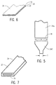
- flux guide parts 24l and 24u are both shown in Figs. 3 and 4 as comprising a single layer of magnetic material. However, flux guide parts 24l and 24u may comprise a laminated structure as shown in Fig. 6.
- the flux guide parts 24l and 24w comprise alternate thin layers of a ferromagnetic material 23 and a non-magnetic material 25.
- Flux guide parts 24l and 24w may also comprise a closed flux structure (Fig. 7) in which the ferromagnetic material 27 has edge closures around the non-magnetic material 29.
- the legs 16r and 16l of the magnetic yoke may also be produced with a laminated or flux closed structure, if desired.
- the MR element 30 (Figs. 2 and 3) is normal to flux guide 24 so that the direction of current flow in the MR element is essentially parallel to the ABS 34, and the MR element is separated from flux guide 24 by the second gap insulation layer 38. Electrical conductor leads 42, 44 provide electrical contact to MR element 30, and READ control circuits 46 are coupled across conductor leads 42, 44.
- MR element 30 is shown as comprising a single layer, it is known in the art that the MR layer 30 may comprise other layers as well, such as biasing layers, for example. In addition, the MR element may require more than two conductor leads.
- the MR element 30 and electrical conductor leads 42 and 44 are arranged so that current flows substantially normal to the flux guide 24 through the MR element 30.
- This arrangement is suitable for many applications.
- the embodiment shown in Fig. 8 becomes increasingly more desirable.
- the MR element 64 is elongated in a direction along the flux guide 24''.
- the electrically conducting leads 66 and 68 are arranged so that the current flow through the MR element 64 is substantially parallel to the flux guide 24''. This arrangement provides increased squares of resistance for narrow track applications.
- Magnetic yoke 16 is defined as an open yoke since the two legs 16l and 16r are, for most of their length, displaced in the direction which would be the cross track direction when the magnetic head 10 is in use. In a preferred embodiment, the distance between the opposite legs 16l and 16r of the magnetic yoke 16 is more than 100 times the write gap 22 length for a majority of the length of the magnetic yoke 16. Coils 18 and 20 are fabricated helically about the legs 16l and 16r respectively of the magnetic yoke 16.
- Each of the coils 18 and 20 are provided with two electrical leads 48, 50 and 52, 54 respectively, and the sense of winding of the coils 18, 20 on legs 16l and 16r magnetic yoke 16 is opposite.
- WRITE control circuits 56 By connecting WRITE control circuits 56 across electrical leads 48 and 54 and connecting electrical leads 50 and 52 together, a WRITE current I produces a flux in the direction of arrow 58 in leg 16l of magnetic yoke 16 and produces a flux in the direction of arrow 60 in leg 16r of magnetic yoke 16.
- This flux provides a substantial magnetomotive potential difference between first pole 12 and second pole 14 which provides an efficient WRITE process.
- a sense current from READ control circuits 46 is passed through electrical leads 42 and 44 through the MR element 30.
- the sense current magnitude is selected at a level which provides a bias so that the MR element 30 is biased to a linear part of its resistance vs. magnetic flux characteristics curve.
- biasing of the MR element 30 may be by means of a current of a chosen low level magnitude in coils 18 and 20.
- biasing of the MR element may be produced by means of a current of a chosen low level magnitude in coil 18 and 20.
- a first current source 49 is connected across terminals 48 and 50, and a second current source 53 is connected across terminals 52 and 54.
- both current sources 49 and 53 produce a current I so that there is no net flux in the central leg of the magnetic yoke.
- current source 49 produces a current i
- current source 53 produces a current -i so that the resulting flux is additive in the centre leg of magnetic yoke 16 where flux guide 24 is located.
- the level of current i utilised for this biasing technique is sufficiently small that the previously recorded data is not disturbed. Signals produced by resistance variation of the MR element 28 due to data previously recorded on recording medium 11 are sensed by the READ control circuits 46 as is conventionally practised for MR sensing.
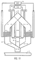
- FIG. 11 An alternate embodiment of the thin film magnetic head is shown in Fig. 11, and this is currently the preferred embodiment.
- the basic head structure remains the same as the Fig. 2 embodiment.
- the back closure 62 of the magnetic yoke 16' is in the form of an inverted V with easy axis orientation as shown by the arrows in Fig. 11.
- the easy axis orientation is established by applying a suitable magnetic field in the direction of the arrows during the deposition of the magnetic material which forms the magnetic yoke 16' and the flux guide 24'.
- the same variations in connections to the coils can be made as described above with respect to the Fig. 2 embodiment.
- the thin film magnetic head 10 is fabricated by the use of suitable deposition and patterning techniques that are known in the art.
- the bottom layer of the coils is deposited first. This is followed by a layer of insulation, either dielectric material such as alumina or hard baked resist. This layer electrically insulates the coils from the yoke structure.
- the part of the magnetic yoke which comprises first pole 12 and extends to the straight leg 16r is deposited next, followed by the deposition of an insulator layer 70 to provide a planar surface for the deposition of the other head components.
- the flux guide 24, the MR layer 30, and the electrical leads are deposited, along with the appropriate insulating layers prior to the deposition of the remainder of the magnetic yoke.
- the insulating layers include hard baked resist to insulate the coils 18, 20 and a mound 72 or non-magnetic spacer member (Fig. 4) to define the zero throat position.
- a mound 72 or non-magnetic spacer member Fig. 4
- patterned dielectric, insulating material such as alumina may also be used.
- the remainder of the magnetic yoke 16 is then deposited and this includes the second pole 14 and a contiguous structure which comprises leg 16l, back closure 26, and leg 16r which is deposited directly contacting the previously deposited layer of magnetic material which extends to first pole 12.
- vias are opened to the bottom coil layer so that the top coil layer can be deposited to provide electrical contact with the bottom coil layer and produce a coil 18 helically wrapped about leg 16l of the magnetic yoke and coil 20 helically wrapped about leg 16r of the magnetic yoke.
- an integrated inductive write/magnetoresistive read thin film magnetic head comprising: an open magnetic yoke having outside legs and a central leg, said outer legs being overlapped at one end to form confronting pole pieces having a transducing gap between said pole pieces, said central leg having an opening and being positioned between said pole pieces at said one end and joined with said outer legs at the other end to produce a symmetrical yoke structure; a magnetoresistive element coupled across said opening in said central leg; and a winding on each of said outside legs wound in a direction so that flux produced by equally energizing said windings is equal and in opposite directions in each of said outside legs.
Landscapes
- Engineering & Computer Science (AREA)
- Manufacturing & Machinery (AREA)
- Magnetic Heads (AREA)
Applications Claiming Priority (2)
| Application Number | Priority Date | Filing Date | Title |
|---|---|---|---|
| US07/661,797 US5164869A (en) | 1991-02-27 | 1991-02-27 | Magnetic recording head with integrated magnetoresistive element and open yoke |
| US661797 | 1991-02-27 |
Publications (3)
| Publication Number | Publication Date |
|---|---|
| EP0501603A2 true EP0501603A2 (fr) | 1992-09-02 |
| EP0501603A3 EP0501603A3 (en) | 1993-06-09 |
| EP0501603B1 EP0501603B1 (fr) | 1995-09-20 |
Family
ID=24655159
Family Applications (1)
| Application Number | Title | Priority Date | Filing Date |
|---|---|---|---|
| EP92300382A Expired - Lifetime EP0501603B1 (fr) | 1991-02-27 | 1992-01-16 | Tête magnétique à film mince |
Country Status (4)
| Country | Link |
|---|---|
| US (1) | US5164869A (fr) |
| EP (1) | EP0501603B1 (fr) |
| JP (1) | JP2500970B2 (fr) |
| DE (1) | DE69204869T2 (fr) |
Cited By (3)
| Publication number | Priority date | Publication date | Assignee | Title |
|---|---|---|---|---|
| EP0501617A2 (fr) * | 1991-02-27 | 1992-09-02 | International Business Machines Corporation | Tête magnétique à film minces pour lire/écrire |
| FR2761477A1 (fr) * | 1997-04-01 | 1998-10-02 | Commissariat Energie Atomique | Capteur de champ magnetique a magnetoresistance |
| EP0883109A2 (fr) * | 1997-06-02 | 1998-12-09 | Deutsche Thomson-Brandt Gmbh | Tambour à têtes à films minces |
Families Citing this family (24)
| Publication number | Priority date | Publication date | Assignee | Title |
|---|---|---|---|---|
| US5490027A (en) * | 1991-10-28 | 1996-02-06 | Censtor Corp. | Gimbaled micro-head/flexure/conductor assembly and system |
| US6600631B1 (en) * | 1989-11-27 | 2003-07-29 | Censtor Corp. | Transducer/flexure/conductor structure for electromagnetic read/write system |
| JPH04351706A (ja) * | 1991-05-30 | 1992-12-07 | Matsushita Electric Ind Co Ltd | 複合型薄膜磁気ヘッド |
| JPH05114119A (ja) * | 1991-10-21 | 1993-05-07 | Fujitsu Ltd | 磁気抵抗効果型磁気ヘツド |
| US5995339A (en) * | 1993-03-18 | 1999-11-30 | Fujitsu Limited | Magnetoresistive head with a front flux guide and an embedded MR element |
| EP0650156A1 (fr) * | 1993-10-21 | 1995-04-26 | Seagate Technology International | Arrangement de contacts pour minimaliser la perturbation inductive dans têtes de lecture magnétoresistives |
| JP2635942B2 (ja) * | 1994-02-10 | 1997-07-30 | インターナショナル・ビジネス・マシーンズ・コーポレイション | 直接アクセス記憶装置のサーボ位置決めの方法及び装置 |
| US5748414A (en) * | 1994-06-24 | 1998-05-05 | Samsung Electro-Mechanics Co., Ltd. | Magnetoresistive element assembly with longitudinal bias |
| US5546256A (en) * | 1994-10-21 | 1996-08-13 | Seagate Technology, Inc. | Inductive transducer with closed-loop pole circumscribing I-shaped pole to reduce leakage flux |
| US6195232B1 (en) * | 1995-08-24 | 2001-02-27 | Torohead, Inc. | Low-noise toroidal thin film head with solenoidal coil |
| US5703740A (en) * | 1995-08-24 | 1997-12-30 | Velocidata, Inc. | Toroidal thin film head |
| US6122149A (en) * | 1997-06-24 | 2000-09-19 | Seagate Technology, Inc. | Magnetic microactuator and inductive sensor having shaped pole configuration |
| JP3180785B2 (ja) * | 1998-11-27 | 2001-06-25 | 日本電気株式会社 | ヨーク型磁気抵抗効果ヘッド、ヨーク型磁気抵抗効果複合薄膜ヘッドおよび磁気記憶装置 |
| US6330128B1 (en) * | 1999-04-26 | 2001-12-11 | International Business Machines Corporation | Magnetic head assembly having open yoke write head with highly defined narrow track width |
| JP2001237469A (ja) * | 2000-02-22 | 2001-08-31 | Fujitsu Ltd | 磁気センサ及びその製造方法 |
| JP2002083403A (ja) * | 2000-09-06 | 2002-03-22 | Hitachi Electronics Eng Co Ltd | 磁気ディスクの書込/読出回路 |
| US20020171975A1 (en) * | 2001-05-15 | 2002-11-21 | Plumer Martin L. | Writing element with no return path |
| US6867940B2 (en) * | 2003-06-16 | 2005-03-15 | Seagate Technology Llc | Method and apparatus for mitigating thermal pole tip protrusion |
| US6975472B2 (en) * | 2003-09-12 | 2005-12-13 | Seagate Technology Llc | Head with heating element and control regime therefor |
| US7440213B2 (en) * | 2005-02-09 | 2008-10-21 | Seagate Technology Llc | Apparatus and method for controlling remnant magnetization in a magnetic recording head |
| US8724263B2 (en) | 2005-08-11 | 2014-05-13 | Seagate Technology Llc | Method for active control of spacing between a head and a storage medium |
| US7808746B2 (en) | 2005-08-11 | 2010-10-05 | Seagate Technology Llc | Method and apparatus for active control of spacing between a head and a storage medium |
| JP2008010123A (ja) * | 2006-06-30 | 2008-01-17 | Toshiba Corp | ヨーク型磁気ヘッド、および磁気ディスク装置 |
| WO2009098760A1 (fr) * | 2008-02-06 | 2009-08-13 | Fujitsu Limited | Élément d'enregistrement, tête magnétique et dispositif d'enregistrement d'informations |
Citations (5)
| Publication number | Priority date | Publication date | Assignee | Title |
|---|---|---|---|---|
| DE2262659B2 (de) * | 1971-12-27 | 1975-10-23 | International Business Machines Corp., Armonk, N.Y. (V.St.A.) | Magnetkopf mit einem magneto-resistiven Dünnfilm-Element und Verfahren zu seiner Herstellung in Dünnfilm-Technik |
| EP0122660A1 (fr) * | 1983-04-05 | 1984-10-24 | Koninklijke Philips Electronics N.V. | Tête magnétique à bande mince de matériau magnétorésistif utilisée comme élément de lecture |
| SU1125651A1 (ru) * | 1983-06-16 | 1984-11-23 | Минский радиотехнический институт | Тонкопленочна магнитна головка |
| EP0218814A1 (fr) * | 1985-10-02 | 1987-04-22 | International Business Machines Corporation | Structure de tête magnétique différentielle de lecture/écriture pour enregistrement à deux pistes |
| EP0238110A1 (fr) * | 1986-02-17 | 1987-09-23 | Koninklijke Philips Electronics N.V. | Tête magnétique à élément magnétorésistif |
Family Cites Families (4)
| Publication number | Priority date | Publication date | Assignee | Title |
|---|---|---|---|---|
| US3921217A (en) * | 1971-12-27 | 1975-11-18 | Ibm | Three-legged magnetic recording head using a magnetorestive element |
| US4300177A (en) * | 1975-07-17 | 1981-11-10 | U.S. Philips Corporation | Thin-film magnetic head for reading and writing information |
| US4566050A (en) * | 1982-12-30 | 1986-01-21 | International Business Machines Corp. (Ibm) | Skew insensitive magnetic read head |
| US4698711A (en) * | 1985-10-02 | 1987-10-06 | International Business Machines Corporation | Simplified, shielded twin-track read/write head structure |
-
1991
- 1991-02-27 US US07/661,797 patent/US5164869A/en not_active Expired - Lifetime
- 1991-12-11 JP JP3327633A patent/JP2500970B2/ja not_active Expired - Fee Related
-
1992
- 1992-01-16 EP EP92300382A patent/EP0501603B1/fr not_active Expired - Lifetime
- 1992-01-16 DE DE69204869T patent/DE69204869T2/de not_active Expired - Fee Related
Patent Citations (5)
| Publication number | Priority date | Publication date | Assignee | Title |
|---|---|---|---|---|
| DE2262659B2 (de) * | 1971-12-27 | 1975-10-23 | International Business Machines Corp., Armonk, N.Y. (V.St.A.) | Magnetkopf mit einem magneto-resistiven Dünnfilm-Element und Verfahren zu seiner Herstellung in Dünnfilm-Technik |
| EP0122660A1 (fr) * | 1983-04-05 | 1984-10-24 | Koninklijke Philips Electronics N.V. | Tête magnétique à bande mince de matériau magnétorésistif utilisée comme élément de lecture |
| SU1125651A1 (ru) * | 1983-06-16 | 1984-11-23 | Минский радиотехнический институт | Тонкопленочна магнитна головка |
| EP0218814A1 (fr) * | 1985-10-02 | 1987-04-22 | International Business Machines Corporation | Structure de tête magnétique différentielle de lecture/écriture pour enregistrement à deux pistes |
| EP0238110A1 (fr) * | 1986-02-17 | 1987-09-23 | Koninklijke Philips Electronics N.V. | Tête magnétique à élément magnétorésistif |
Non-Patent Citations (1)
| Title |
|---|
| SOVIET INVENTIONS ILLUSTRATED Section EI, Week 8523, 18 July 1985 Derwent Publications Ltd., London, GB; Class T03, AN 85-140089/23 & SU-A-1 125 651 (MINSK WIRELESS ENG) 23 November 1984 * |
Cited By (6)
| Publication number | Priority date | Publication date | Assignee | Title |
|---|---|---|---|---|
| EP0501617A2 (fr) * | 1991-02-27 | 1992-09-02 | International Business Machines Corporation | Tête magnétique à film minces pour lire/écrire |
| EP0501617A3 (fr) * | 1991-02-27 | 1994-04-27 | Ibm | |
| FR2761477A1 (fr) * | 1997-04-01 | 1998-10-02 | Commissariat Energie Atomique | Capteur de champ magnetique a magnetoresistance |
| WO1998044359A1 (fr) * | 1997-04-01 | 1998-10-08 | Commissariat A L'energie Atomique | Capteur de champ magnetique a magnetoresistance |
| EP0883109A2 (fr) * | 1997-06-02 | 1998-12-09 | Deutsche Thomson-Brandt Gmbh | Tambour à têtes à films minces |
| EP0883109A3 (fr) * | 1997-06-02 | 2000-06-28 | Deutsche Thomson-Brandt Gmbh | Tambour à têtes à films minces |
Also Published As
| Publication number | Publication date |
|---|---|
| DE69204869T2 (de) | 1996-05-02 |
| JPH0628633A (ja) | 1994-02-04 |
| EP0501603B1 (fr) | 1995-09-20 |
| US5164869A (en) | 1992-11-17 |
| DE69204869D1 (de) | 1995-10-26 |
| JP2500970B2 (ja) | 1996-05-29 |
| EP0501603A3 (en) | 1993-06-09 |
Similar Documents
| Publication | Publication Date | Title |
|---|---|---|
| EP0501603B1 (fr) | Tête magnétique à film mince | |
| US5446613A (en) | Magnetic head assembly with MR sensor | |
| KR100426768B1 (ko) | 자기저항효과헤드 | |
| US6621664B1 (en) | Perpendicular recording head having integrated read and write portions | |
| US6914759B2 (en) | Giant magnetoresistive sensor having selfconsistent demagnetization fields | |
| US20060256471A1 (en) | Magnetic writing pole and a perpendicular writing element | |
| US6325947B1 (en) | Method for forming low profile multi-layer coil merged thin film magnetic head | |
| EP0189793B1 (fr) | Dispositif d'enregistrement et de reproduction magnétique | |
| JP2000105912A (ja) | 磁気トンネル接合センサおよびディスク・ドライブ・システム | |
| US5436779A (en) | Integrated yoke magnetoresistive transducer with magnetic shunt | |
| JPH0786032A (ja) | 磁性膜構造 | |
| KR0162119B1 (ko) | 엣지가 바이어스된 자기 저항 센서 | |
| US20050195535A1 (en) | Adaptive domain stabilization for magnetic recording read sensors | |
| KR100259431B1 (ko) | 강화된 자기저항 효과를 갖는 자기저항 센서 | |
| US6972932B2 (en) | High-efficiency single-turn write head for high-speed recording | |
| JPH09282618A (ja) | 磁気抵抗効果型ヘッド及び磁気記録再生装置 | |
| US6583970B1 (en) | Magnetoresistive head device incorporating joints between magnetoresistive layer and sense current conductors | |
| US5894385A (en) | Highly sensitive magnetoresistive sensor with a series flux guide | |
| JP2002133615A (ja) | 磁気抵抗効果型磁気ヘッド | |
| JPH064832A (ja) | 複合型薄膜磁気ヘッド | |
| US6600636B1 (en) | Magnetic head with write element offset from read element | |
| JPH08115511A (ja) | フラックスガイド型gmrヘッド | |
| JPH08339514A (ja) | 磁気記録再生装置 | |
| JPH11213332A (ja) | 薄膜磁気ヘッド及び磁気ディスク装置 | |
| EP0501617A2 (fr) | Tête magnétique à film minces pour lire/écrire |
Legal Events
| Date | Code | Title | Description |
|---|---|---|---|
| PUAI | Public reference made under article 153(3) epc to a published international application that has entered the european phase |
Free format text: ORIGINAL CODE: 0009012 |
|
| AK | Designated contracting states |
Kind code of ref document: A2 Designated state(s): DE FR GB |
|
| 17P | Request for examination filed |
Effective date: 19921210 |
|
| PUAL | Search report despatched |
Free format text: ORIGINAL CODE: 0009013 |
|
| AK | Designated contracting states |
Kind code of ref document: A3 Designated state(s): DE FR GB |
|
| 17Q | First examination report despatched |
Effective date: 19941122 |
|
| GRAA | (expected) grant |
Free format text: ORIGINAL CODE: 0009210 |
|
| AK | Designated contracting states |
Kind code of ref document: B1 Designated state(s): DE FR GB |
|
| REF | Corresponds to: |
Ref document number: 69204869 Country of ref document: DE Date of ref document: 19951026 |
|
| ET | Fr: translation filed | ||
| PLBE | No opposition filed within time limit |
Free format text: ORIGINAL CODE: 0009261 |
|
| STAA | Information on the status of an ep patent application or granted ep patent |
Free format text: STATUS: NO OPPOSITION FILED WITHIN TIME LIMIT |
|
| 26N | No opposition filed | ||
| PGFP | Annual fee paid to national office [announced via postgrant information from national office to epo] |
Ref country code: FR Payment date: 19970120 Year of fee payment: 6 |
|
| PGFP | Annual fee paid to national office [announced via postgrant information from national office to epo] |
Ref country code: DE Payment date: 19970128 Year of fee payment: 6 |
|
| PG25 | Lapsed in a contracting state [announced via postgrant information from national office to epo] |
Ref country code: FR Free format text: THE PATENT HAS BEEN ANNULLED BY A DECISION OF A NATIONAL AUTHORITY Effective date: 19980131 |
|
| PG25 | Lapsed in a contracting state [announced via postgrant information from national office to epo] |
Ref country code: DE Free format text: LAPSE BECAUSE OF NON-PAYMENT OF DUE FEES Effective date: 19981001 |
|
| REG | Reference to a national code |
Ref country code: FR Ref legal event code: ST |
|
| REG | Reference to a national code |
Ref country code: GB Ref legal event code: IF02 |
|
| REG | Reference to a national code |
Ref country code: GB Ref legal event code: 732E |
|
| PGFP | Annual fee paid to national office [announced via postgrant information from national office to epo] |
Ref country code: GB Payment date: 20070108 Year of fee payment: 16 |
|
| GBPC | Gb: european patent ceased through non-payment of renewal fee |
Effective date: 20080116 |
|
| PG25 | Lapsed in a contracting state [announced via postgrant information from national office to epo] |
Ref country code: GB Free format text: LAPSE BECAUSE OF NON-PAYMENT OF DUE FEES Effective date: 20080116 |