EP0499208B2 - Telescopic jib for mobile cranes or the like - Google Patents
Telescopic jib for mobile cranes or the like Download PDFInfo
- Publication number
- EP0499208B2 EP0499208B2 EP92102268A EP92102268A EP0499208B2 EP 0499208 B2 EP0499208 B2 EP 0499208B2 EP 92102268 A EP92102268 A EP 92102268A EP 92102268 A EP92102268 A EP 92102268A EP 0499208 B2 EP0499208 B2 EP 0499208B2
- Authority
- EP
- European Patent Office
- Prior art keywords
- profile
- legs
- section
- sections
- telescopic
- Prior art date
- Legal status (The legal status is an assumption and is not a legal conclusion. Google has not performed a legal analysis and makes no representation as to the accuracy of the status listed.)
- Expired - Lifetime
Links
- 238000004519 manufacturing process Methods 0.000 abstract description 5
- 238000005452 bending Methods 0.000 description 7
- 238000010586 diagram Methods 0.000 description 3
- 239000003351 stiffener Substances 0.000 description 3
- 241000237983 Trochidae Species 0.000 description 2
- 230000002349 favourable effect Effects 0.000 description 2
- 230000035945 sensitivity Effects 0.000 description 2
- UQMRAFJOBWOFNS-UHFFFAOYSA-N butyl 2-(2,4-dichlorophenoxy)acetate Chemical compound CCCCOC(=O)COC1=CC=C(Cl)C=C1Cl UQMRAFJOBWOFNS-UHFFFAOYSA-N 0.000 description 1
- 239000002131 composite material Substances 0.000 description 1
- 238000010276 construction Methods 0.000 description 1
- 230000007423 decrease Effects 0.000 description 1
- 230000005484 gravity Effects 0.000 description 1
- 238000012423 maintenance Methods 0.000 description 1
- 238000005096 rolling process Methods 0.000 description 1
- 230000003068 static effect Effects 0.000 description 1
Images

Classifications
-
- B—PERFORMING OPERATIONS; TRANSPORTING
- B66—HOISTING; LIFTING; HAULING
- B66C—CRANES; LOAD-ENGAGING ELEMENTS OR DEVICES FOR CRANES, CAPSTANS, WINCHES, OR TACKLES
- B66C23/00—Cranes comprising essentially a beam, boom, or triangular structure acting as a cantilever and mounted for translatory of swinging movements in vertical or horizontal planes or a combination of such movements, e.g. jib-cranes, derricks, tower cranes
- B66C23/62—Constructional features or details
- B66C23/64—Jibs
- B66C23/70—Jibs constructed of sections adapted to be assembled to form jibs or various lengths
- B66C23/701—Jibs constructed of sections adapted to be assembled to form jibs or various lengths telescopic
- B66C23/705—Jibs constructed of sections adapted to be assembled to form jibs or various lengths telescopic telescoped by hydraulic jacks
-
- B—PERFORMING OPERATIONS; TRANSPORTING
- B66—HOISTING; LIFTING; HAULING
- B66C—CRANES; LOAD-ENGAGING ELEMENTS OR DEVICES FOR CRANES, CAPSTANS, WINCHES, OR TACKLES
- B66C23/00—Cranes comprising essentially a beam, boom, or triangular structure acting as a cantilever and mounted for translatory of swinging movements in vertical or horizontal planes or a combination of such movements, e.g. jib-cranes, derricks, tower cranes
- B66C23/62—Constructional features or details
- B66C23/64—Jibs
- B66C23/70—Jibs constructed of sections adapted to be assembled to form jibs or various lengths
- B66C23/701—Jibs constructed of sections adapted to be assembled to form jibs or various lengths telescopic
- B66C23/708—Jibs constructed of sections adapted to be assembled to form jibs or various lengths telescopic locking devices for telescopic jibs
Definitions
- the invention relates to a telescopic boom for mobile cranes, consisting of one on the Vehicle or its superstructure pivoted outer link, in which several telescopically collapsible and extendable Telescopic shots are held, each shot with bearings for the shot carried in this provided and lockable with this shot and wherein a hydraulic pressure medium piston-cylinder unit to extend and retract the individual Shots are provided.
- the individual telescopic shots essentially one box-like profile with the lower straps of the individual shots flat V-shaped profiles or have flat trough-shaped profiles that by angled from a flat middle web part Legs are formed.
- These lower ones Belts are with the edge areas facing down pointing leg of U-shaped profiled parts with rounded corners between their web parts and legs to box-shaped Welded profiles, being in the area of Welded joints additionally stiffening strut-like sheets can be welded.
- the individual telescopic shots are on top of each other the channel-shaped lower chords after the known from DE-PS 21 48 966 pressure distribution ratio stored, being in the area of the upper rounded corners of the box profiles the bearing forces by rolling or shaped accordingly Camp shoes are transferred.
- the lower chord the is mainly loaded by bending forces through its V-shape or the two longitudinal, the gaps forming the channel shape are stiffened and secured against dents.
- Telescopic booms are not only bent, but also on torsion charged. They work in the lower flange trough or V-shaped cross section arranged Bearing elements against rotation. But is the telescopic boom with a luffing needle provided, this is via a rear A-frame or the like guyed by guy ropes so that a Guide in the bearing elements that transmits torsional forces the V-shaped lower chords can be when the moment acting backwards is equal to or greater than that to the front acting and resulting from load and luffing boom weight resulting moment.
- the object of the invention is a telescopic boom to create the type specified at the beginning, which is very rigid and resistant to buckling of his individual shots through a simple and economically producible construction distinguished.
- the profile according to the invention exists based on its horizontal axis from different Profile parts while it's his vertical axis is symmetrical.
- the profile according to the invention is particularly favorably the requirements of a telescopic boom fair.
- the profiles of each A telescopic boom shots are during of the company primarily in its upper area on train and in its lower area Stressed so that the lower area is strong is sensitive to bulging.
- Convention profiles which were either box-shaped or outgoing of a box shape with a lower V-shaped Profile parts were provided, were increased the buckling stiffness inside and / or outside in the profile stiffened sheet welded.
- the profile according to the invention is particularly favorable Way the demands of a telescopic boom fair because the lower one is highly sensitive to bulging Area consists of a round profile, which is much less sensitive to buckling than box-shaped Profiles.
- the sensitivity to buckling of the lower part of the profile increases with the increasing compressive stress, i.e. Towards the lower vertex line.
- the configuration of the lower one is therefore favorable Profile part in the form of a semi-ellipse, because this in the apex area the smallest radius of curvature has and therefore in the area with the greatest compressive stress the least sensitivity to buckling owns.
- the legs of the upper profile part are standing perpendicular to the straight line forming the top chord Bridge part. Because the upper profile part on train is claimed, the risk of buckling is low, so that the straight profile legs are accepted.
- the top shell of each shot can be made be folded in one piece over the entire length, so that there are no welds in the draft zone and especially no transverse welds available.
- the flat upper web part of the upper profile part also for maintenance purposes Expedient, as these can be committed safely can.
- the upper profile part can also be used be sprayed on a rough surface, so that the required sliding security when walking is.
- the piston rod On that of the outer link 1 bordered part is in the joint 4 the piston rod a hydraulic piston-cylinder unit 5 articulated.
- the link piece and the other telescopic ones Shots are in the area with their ends provided collar-like stiffeners 8-10 on which Hydraulic piston cylinder units provided with locking bolts are arranged.
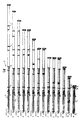
- the innermost telescopic shot is, as from Fig. 1st can be seen at its outer end with a Provide roller head.
- FIG. 2 is the cross section through a Telescopic shot or an outer link of one Telescopic boom that can be seen from a lower semi-elliptical profile part 40 and an upper semi-box-shaped profile part 41, the Legs in a horizontal parting plane welded together by welds 42, 43 are.
- the legs 44,45 of the upper half-box-shaped Profile parts are with the upper web part 46 through curved areas 47, 48 with the bending radius RL connected.
- the lower profile part 40 is through a shell with a semi-elliptical cross-section formed, the profile shape with great approximation an ellipse through the three radii ri, Rmi and Ri can be described.
- the lower part has the shape of a half ellipse, which is the lower constructive Profile shell forms.
- the lower part can for reasons of manufacture by dimension V lengthened at the top, making the dimension H2 the Top shell is shortened accordingly.
- the compressive stress (-) is due to the risk of buckling often the most critical stress thin-walled hollow profiles.
- the greatest bending compressive stress arises from the main load of the boom around the axis X-X (X direction) in lower vertex of radius ri.
- the lateral load or deflection of the Boom around the Y-Y axis (Y direction) in both Direction causes in the profile sidewalls Compressive or tensile stresses, the size of which in Ratio of the distance to the axis of inertia Y-Y results.
Landscapes
- Engineering & Computer Science (AREA)
- Mechanical Engineering (AREA)
- Jib Cranes (AREA)
Abstract
Description
Die Erfindung betrifft einen Teleskopausleger für Fahrzeugkrane, bestehend aus einem auf dem Fahrzeug bzw. dessen Oberwagen schwenkbar gelagerten äußeren Anlenkstück, in dem mehrere teleskopartig zusammenschiebbare und ausfahrbare Teleskopschüsse gehaltert sind, wobei jeder Schuß mit Lagerungen für den in diesem geführten Schuß versehen und mit diesem Schuß verriegelbar ist und wobei eine hydraulische Druckmittel-Kolben-Zylinder-Einheit zum Aus- und Einfahren der einzelnen Schüsse vorgesehen ist.The invention relates to a telescopic boom for mobile cranes, consisting of one on the Vehicle or its superstructure pivoted outer link, in which several telescopically collapsible and extendable Telescopic shots are held, each shot with bearings for the shot carried in this provided and lockable with this shot and wherein a hydraulic pressure medium piston-cylinder unit to extend and retract the individual Shots are provided.
Bei einem beispielsweise aus der DE-B-21 48 966 bekannten Teleskopausleger dieser Art weisen die einzelnen Teleskopschüsse ein im wesentlichen kastenartiges Profil auf, wobei die unteren Gurte der einzelnen Schüsse flache V-förmige Profile oder flache rinnenförmige Profile aufweisen, die durch von einem ebenen mittleren stegteil abgewinkelte Schenkel gebildet sind. Diese unteren Gurte sind mit den Randbereichen der nach unten weisenden Schenkel von U-förmig profilierten Profilteilen mit abgerundeten Eckbereichen zwischen deren Stegteilen und Schenkeln zu kastenförmigen Profilen verschweißt, wobei im Bereich der Schweißverbindungen zusätzlich noch aussteifende strebenartige Bleche eingeschweißt sein können. Die einzelnen Teleskopschüsse sind ineinander auf den rinnenförmig profilierten Untergurten nach dem aus der DE-PS 21 48 966 bekannten Druckverteilungsverhältnis gelagert, wobei im Bereich der oberen angerundeten Ecken der Kastenprofile die Lagerkräfte durch Rollen oder entsprechend geformte Lagerschuhe übertragen werden. Um die Seitenwandungen des U-förmigen Profilteils gegen Beulen zu schützen, sind auf die Innen- oder Außenseite der Schenkel des Profils U-förmig profilierte Beulsteifen eingeschweißt. Der Untergurt, der hauptsächlich durch Biegekräfte belastet ist, ist durch seine V-Form oder die beiden längsverlaufenden, die Rinnenform bildenden Knicke ausgesteift und gegen Beulen gesichert.In one example from DE-B-21 48 966 known telescopic boom of this type the individual telescopic shots essentially one box-like profile with the lower straps of the individual shots flat V-shaped profiles or have flat trough-shaped profiles that by angled from a flat middle web part Legs are formed. These lower ones Belts are with the edge areas facing down pointing leg of U-shaped profiled parts with rounded corners between their web parts and legs to box-shaped Welded profiles, being in the area of Welded joints additionally stiffening strut-like sheets can be welded. The individual telescopic shots are on top of each other the channel-shaped lower chords after the known from DE-PS 21 48 966 pressure distribution ratio stored, being in the area of the upper rounded corners of the box profiles the bearing forces by rolling or shaped accordingly Camp shoes are transferred. Around the side walls of the U-shaped profile part against dents are to be protected on the inside or outside the leg of the profile profiled U-shaped Bulge stiffeners welded in. The lower chord, the is mainly loaded by bending forces through its V-shape or the two longitudinal, the gaps forming the channel shape are stiffened and secured against dents.
Der bekannte Teleskopausleger ist trotz der eingeschweißten Beulsteifen und der Knicklinien nicht nur gegen Beulen empfindlich, er laßt sich darüber hinaus wegen seiner komplizierten Querschnittsform auch nur mit erhöhtem Aufwand herstellen. Teleskopausleger werden nicht nur auf Biegung, sondern darüber hinaus auch auf Torsion belastet. Dabei wirken die in dem Untergurt mit rinnen- oder V-förmigen Querschnitt angeordneten Lagerelemente einer Verdrehung entgegen. Ist aber der Teleskopausleger mit einer wippbaren Nadel versehen, wird dieser über einen hinteren A-Bock o.dgl. durch Abspannseile abgespannt, so daß eine Torsionskräfte übertragende Führung in den Lagerelementen der V-förmigen Untergurte aufgehoben werden kann, wenn das nach hinten wirkende Moment gleich oder größer ist als das nach vorne wirkende und sich aus Last- und Nadelauslegergewicht ergebende Moment.The well-known telescopic boom is despite the welded buckling stiffeners and the fold lines not only sensitive to bumps, he lets himself moreover because of its complicated cross-sectional shape even produce with increased effort. Telescopic booms are not only bent, but also on torsion charged. They work in the lower flange trough or V-shaped cross section arranged Bearing elements against rotation. But is the telescopic boom with a luffing needle provided, this is via a rear A-frame or the like guyed by guy ropes so that a Guide in the bearing elements that transmits torsional forces the V-shaped lower chords can be when the moment acting backwards is equal to or greater than that to the front acting and resulting from load and luffing boom weight resulting moment.
Um einen Teleskopausleger unabhängig von seinem Verschiebelager eine ausreichende Torsionssteifigkeit zu verleihen, ist es bekannt, die einzelnen Auslegerschüsse miteinander zu verbolzen und zusätzlich noch mit seitlichen Führungslagern zu versehen.To a telescopic boom regardless of its sliding bearing has sufficient torsional rigidity to lend it is known to to bolt individual boom sections together and additionally with lateral guide bearings to provide.
Aufgabe der Erfindung ist es, einen Teleskopausleger der eingangs angegebenen Art zu schaffen, der sich bei großer Biegesteifigkeit und Beulunempfindlichkeit seiner einzelnen Schüsse durch eine einfache und wirtschaftlich herstellbare Konstruktion auszeichnet.The object of the invention is a telescopic boom to create the type specified at the beginning, which is very rigid and resistant to buckling of his individual shots through a simple and economically producible construction distinguished.
Erfindungsgemäß wird diese Aufgabe durch die Merkmale des Patentanspruchs gelöst. Das erfindungsgemäße Profil besteht bezogen auf seine horizontale Achse aus unterschiedlichen Profilteilen, während es um seine vertikale Achse symmetrisch ist.According to the invention, this object is achieved by the features of the patent claim. The profile according to the invention exists based on its horizontal axis from different Profile parts while it's his vertical axis is symmetrical.
Das erfindungsgemäße Profil wird in besonders günstiger Weise den Anforderungen an einen Teleskopausleger gerecht. Die Profile der einzelnen Schüsse eines Teleskopauslegers sind während des Betriebes in erster Linie in ihrem oberen Bereich auf Zug und in ihrem unteren Bereich auf Druck beansprucht, so daß der untere Bereich stark beulempfindlich ist. Bei herkömmlichen Profilen, die entweder eine Kastenform aufwiesen oder ausgehend von einer Kastenform mit einem unteren V-förmigen Profilteil versehen waren, wurden zur Erhöhung der Beulsteifigkeit innen und/oder außen in das Profil aussteifende Bleche eingeschweißt. Das erfindungsgemäße Profil wird in besonders günstiger Weise den Beanspruchungen eines Teleskopauslegers gerecht, weil der untere stark beulempfindliche Bereich aus einem runden Profil besteht, das sehr viel weniger beulempfindlich ist als kastenförmige Profile.The profile according to the invention is particularly favorably the requirements of a telescopic boom fair. The profiles of each A telescopic boom shots are during of the company primarily in its upper area on train and in its lower area Stressed so that the lower area is strong is sensitive to bulging. With conventional profiles, which were either box-shaped or outgoing of a box shape with a lower V-shaped Profile parts were provided, were increased the buckling stiffness inside and / or outside in the profile stiffened sheet welded. The profile according to the invention is particularly favorable Way the demands of a telescopic boom fair because the lower one is highly sensitive to bulging Area consists of a round profile, which is much less sensitive to buckling than box-shaped Profiles.
Die Beulempfindlichkeit des unteren Profilteils nimmt mit der wachsenden Druckspannung, also in Richtung auf die untere Scheitellinie zu. Besonders günstig ist daher die Ausgestaltung des unteren Profilteils in Form einer Halbellipse, weil diese in ihrem Scheitelbereich den kleinsten Krümmungsradius aufweist und daher in dem Bereich mit der größten Druckspannung die geringste Beulempfindlichkeit besitzt.The sensitivity to buckling of the lower part of the profile increases with the increasing compressive stress, i.e. Towards the lower vertex line. Especially The configuration of the lower one is therefore favorable Profile part in the form of a semi-ellipse, because this in the apex area the smallest radius of curvature has and therefore in the area with the greatest compressive stress the least sensitivity to buckling owns.
Die Schenkel des oberen Profilteils stehen rechtwinkelig zu dem den Obergurt bildenden geraden Stegteil. Da der obere Profilteil auf Zug beansprucht wird, ist die Beulgefahr gering, so daß die geraden Profilschenkel in Kauf genommen werden.The legs of the upper profile part are standing perpendicular to the straight line forming the top chord Bridge part. Because the upper profile part on train is claimed, the risk of buckling is low, so that the straight profile legs are accepted.
Die Oberschale eines jeden Schusses kann aus einem Stück in der gesamten Länge gekantet werden, so daß in der Zugzone keine Schweißnähte und insbesondere keine querverlaufende Schweißnähte vorhanden sind.The top shell of each shot can be made be folded in one piece over the entire length, so that there are no welds in the draft zone and especially no transverse welds available.
Bei der Fertigung der Auslegerschüsse kann die Oberschale auf eine gerade Platte aufgelegt werden und braucht nicht, wie bei einem vollständigen ovalen Auslegerprofil in besonderen Einrichtungen festgehalten zu werden.In the manufacture of the boom sections the upper shell is placed on a straight plate are and do not need, as with a complete oval boom profile in special facilities to be held.
Im praktischen Kranbetrieb schafft das halbkastenförmige obere Profilteil zusätzliche Vorteile, die darin bestehen, daß sich das Hubseil auf den breiten Obergurt ablegen kann, ohne seitlich abzurutschen. Weiterhin ist der flache obere Stegteil des oberen Profilteils auch zu Wartungszwecken zweckmäßig, da dieser gefahrlos begangen werden kann. Das obere Profilteil kann zusätzlich auch mit einem rauhen Belag gespritzt werden, so daß die erforderliche Gleitsicherheit beim Begehen gegeben ist. In practical crane operation, this creates a half-box shape upper profile part additional benefits that consist in the fact that the hoisting rope is on the wide Can remove the top chord without sliding sideways. Furthermore, the flat upper web part of the upper profile part also for maintenance purposes Expedient, as these can be committed safely can. The upper profile part can also be used be sprayed on a rough surface, so that the required sliding security when walking is.
Ein Ausführungsbeispiel der Erfindung wird
nachstehend anhand der Zeichnung näher beschrieben.
In dieser zeigt
einen Teleskopausleger in unterschiedlichen Ausfahrzuständen seiner Teleskopschüsse,
einen Querschnitt durch einen Teleskopschuß bzw. ein äußeres Anlenkstück mit einem aus einem halbkastenförmigen Teil und einem runden Teil zusammengesetztem Profil, und
die zugehörigen Biege-, Biegezug-, Biegedruck- und die zusammengesetzten Beanspruchungen darstellenden Diagramme.
a telescopic boom in different extension states of its telescopic sections,
a cross section through a telescopic section or an outer link piece with a profile composed of a half-box-shaped part and a round part, and
the associated bending, bending tensile, bending pressure and composite stress diagrams.
Wie aus Fig. 1 ersichtlich ist, ist das äußere
Anlenkstück 1 des Teleskopauslegers 2 mit einem
Gelenkstück 3 versehen, über das dieses an dem
Oberwagen eines Krans, Kranfahrzeuges o.dgl. angelenkt
ist. An dem von dem äußeren Anlenkstück
1 eingefaßten Teil ist im Gelenk 4 die Kolbenstange
einer hydraulischen Kolben-Zylinder-Einheit 5
angelenkt.As can be seen from Fig. 1, the
Parallel zu der Kolbenzylindereinheit 5 ist oberhalb
von dieser an dem Auslegeranlenkstück 4
verdrehsicher ein Vierkantprofil 6 angelenkt.Parallel to the piston-
Das Anlenkstück und die weiteren austeleskopierbaren Schüsse sind im Bereich ihrer Enden mit kragenartigen Versteifungen 8-10 versehen, auf denen mit Verriegelungsbolzen versehene Druckmittelkolbenzylindereinheiten angeordnet sind. Der innerste austeleskopierbare Schuß ist, wie aus Fig. 1 ersichtlich ist, an seinem äußeren Ende mit einem Rollenkopf versehen.The link piece and the other telescopic ones Shots are in the area with their ends provided collar-like stiffeners 8-10 on which Hydraulic piston cylinder units provided with locking bolts are arranged. The innermost telescopic shot is, as from Fig. 1st can be seen at its outer end with a Provide roller head.
Aus Fig. 2 ist der Querschnitt durch einen
Teleskopschuß bzw. ein äußeres Anlenkstück eines
Teleskopauslegers ersichtlich, das aus einem unteren
halbelliptischen Profilteil 40 und einem oberen
halbkastenförmigen Profilteil 41 besteht, dessen
Schenkel in einer horizontalen Trennebene
durch Schweißnähte 42,43 miteinander verschweißt
sind. Die Schenkel 44,45 des oberen halbkastenförmigen
Profilteils sind mit dem oberen Stegteil
46 durch gekrümmte Bereiche 47,48 mit dem Biegeradius
RL verbunden. Das untere Profilteil 40 ist
durch eine Schale mit halbelliptischen Querschnitt
gebildet, wobei sich die Profilform mit großer Annäherung
an eine Ellipse durch die drei Radien ri,
Rmi und Ri beschreiben läßt. Aus Gründen der
Fertigung kann eine Vereinfachung vorgenommen
werden, wenn die Querschnittsform nur durch die
beiden Radien ri und Rmi definiert wird. Die Ellipsenform
ändert sich durch die beschriebenen Vereinfachungen
bei der Herstellung nur geringfügig,
wobei diese aus statischer Sicht unter Umständen
sogar günstig sein können. Denn der Bereich der
beulsteifen Schale mit dem Radius ri bzw. dem
Winkel Ey2 wird größer und der Radius Rmi kann
bis annähernd zur Profilmitte geführt werden. Dadurch
entfällt der größere und somit weniger beulsichere
Bereich mit dem Radius Ri. Hierdurch wird
die Unterschale 40 insgesamt beulsteifer, da die
Beulsicherheit linear mit der Vergrößerung der Radien
abnimmt. 2 is the cross section through a
Telescopic shot or an outer link of one
Telescopic boom that can be seen from a lower
Bei dem Profil nach den Fig. 2 ist die konstruktive Mitte zwischen den Maßen H1 und H2 die Profilmitte. Der untere Teil weist die Form einer halben Ellipse auf, die gleichzeitig die untere konstruktive Profilschale bildet. Der untere Teil kann aus Gründen der Fertigung durch das Maß V nach oben verlängert werden, wodurch das Maß H2 der Oberschale entsprechend verkürzt wird.2 is the constructive middle between the dimensions H1 and H2 the center of the profile. The lower part has the shape of a half ellipse, which is the lower constructive Profile shell forms. The lower part can for reasons of manufacture by dimension V lengthened at the top, making the dimension H2 the Top shell is shortened accordingly.
Wenn die Blechstärken der unteren Schale t1 bzw. t2 mit der Stärke der Oberschale t3 und die Profilhöhen H1 bzw. H2 so abgestimmt werden, daß die Schwerpunktachse sich in der Nähe der Profilmitte befindet, ergeben sich folgende Spannungsverhältnisse, die jeweils in den Diagrammen mit den nachgestellten Buchstaben a bis h dargestellt sind:If the sheet thicknesses of the lower shell t1 or t2 with the thickness of the upper shell t3 and the Profile heights H1 and H2 can be adjusted that the center of gravity is near the Center of the profile, the following tension relationships arise, each in the diagrams with the following Letters a to h are shown:
Die Druckspannung (-) ist wegen der Beulgefahr häufig die kritischste Beanspruchung bei dünnwandigen Hohlprofilen. Die größte Biege-Druckspannung entsteht durch die Hauptbelastung des Auslegers um die Achse X-X (X-Richtung) im unteren Scheitelpunkt des Radius ri.The compressive stress (-) is due to the risk of buckling often the most critical stress thin-walled hollow profiles. The greatest bending compressive stress arises from the main load of the boom around the axis X-X (X direction) in lower vertex of radius ri.
Die seitliche Belastung bzw. Ausbiegung des Auslegers um die Achse Y-Y (Y-Richtung) in beiden Richtungen bewirkt in den Profil-Seitenwänden Druck- bzw. Zugspannungen, deren Größe sich im Verhältnis des Abstandes zur Trägheitsachse Y-Y ergibt.The lateral load or deflection of the Boom around the Y-Y axis (Y direction) in both Direction causes in the profile sidewalls Compressive or tensile stresses, the size of which in Ratio of the distance to the axis of inertia Y-Y results.
Bei dem Profil sind im unteren Scheitelpunkt diese Spannungen = 0, so daß hier keine Veränderung der Druckspannung aus der X-Richtung entsteht. An der Oberkante des Profils werden infolge der Radien RL die Spannungen aus der Y-Richtung vermindert.The profile is at the bottom vertex these voltages = 0, so that here none Change in compressive stress from the X direction arises. Be on the top edge of the profile due to the radii RL, the stresses from the Y direction reduced.
Entlang der Seitenwand nach oben addieren sich die Zug- bzw. Druckspannungen aus der Y-Richtung mit den Biegespannungen aus der X-Richtung.Add up along the side wall the tensile or compressive stresses from the Y direction with the bending stresses from the X direction.
Diese Spannungsverhältnisse sind zu jedem der drei Profile in den zugehörigen Diagrammen dargestellt.These tensions are with everyone of the three profiles in the associated diagrams shown.
Bei dem Profil ist durch den gleichmäßigen, seitlichen Spannungsverlauf in der oberen Profilhälfte bzw. der oberen Schale der Aufbau der Druckspannung in der oberen beulempfindlichen Seitenwand am geringsten.With the profile is through the uniform, lateral tension in the upper profile half or the upper shell of the Build-up of compressive stress in the upper dent sensitive Sidewall least.
Claims (1)
- A telescopic jib (2) for cranes, preferably mobile cranes, consisting of an outer articulation component (1) pivotably mounted on the vehicle or its upper chassis, wherein there are mounted several telescopically retractable and extendable telescopic sections, in which arrangement each section is provided with bearing means for the section carried therein and is lockable with this section, and wherein provision is made for a hydraulic pressure medium piston-cylinder unit for the outward movement and retraction of the individual sections,
characterized inthat the articulation component (1) and the sections consist of profiles, each of which has in the horizontal position pivoted onto the vehicle, a lower round part (40) and an upper half-box-shaped part (41), and whose legs (44, 45) directed towards each other are welded together,that the lower profile part (40) approximately has the shape of a half ellipse with the apex formed by the small radius, that the legs of the lower round profile part (40) are tangentially joined to the straight legs (44, 45) of the upper profile part (41), andthat the legs (44, 45) of the upper profile part (41) are disposed at right angles to the straight web part (46) which forms the upper boom.
Priority Applications (1)
| Application Number | Priority Date | Filing Date | Title |
|---|---|---|---|
| DE9218841U DE9218841U1 (en) | 1991-02-11 | 1992-02-11 | Telescopic boom for mobile cranes or the like |
Applications Claiming Priority (6)
| Application Number | Priority Date | Filing Date | Title |
|---|---|---|---|
| DE9101533 | 1991-02-11 | ||
| DE9101533U | 1991-02-11 | ||
| DE9102552U | 1991-03-04 | ||
| DE9102552U DE9102552U1 (en) | 1991-02-11 | 1991-03-04 | Telescopic boom for mobile cranes or similar |
| DE9113981U | 1991-11-11 | ||
| DE9113981U DE9113981U1 (en) | 1991-11-11 | 1991-11-11 | Telescopic boom for mobile cranes or similar |
Publications (4)
| Publication Number | Publication Date |
|---|---|
| EP0499208A2 EP0499208A2 (en) | 1992-08-19 |
| EP0499208A3 EP0499208A3 (en) | 1993-05-19 |
| EP0499208B1 EP0499208B1 (en) | 1995-06-14 |
| EP0499208B2 true EP0499208B2 (en) | 2001-10-17 |
Family
ID=27208262
Family Applications (1)
| Application Number | Title | Priority Date | Filing Date |
|---|---|---|---|
| EP92102268A Expired - Lifetime EP0499208B2 (en) | 1991-02-11 | 1992-02-11 | Telescopic jib for mobile cranes or the like |
Country Status (3)
| Country | Link |
|---|---|
| EP (1) | EP0499208B2 (en) |
| AT (1) | ATE123743T1 (en) |
| DE (1) | DE59202474D1 (en) |
Cited By (1)
| Publication number | Priority date | Publication date | Assignee | Title |
|---|---|---|---|---|
| EP2078693A1 (en) | 2008-01-09 | 2009-07-15 | Kobelco Cranes Co., Ltd. | Telescopic boom |
Families Citing this family (9)
| Publication number | Priority date | Publication date | Assignee | Title |
|---|---|---|---|---|
| DE4344795A1 (en) * | 1993-12-28 | 1995-06-29 | Liebherr Werk Ehingen | Mobile crane with a telescopic boom |
| DE19624312C2 (en) * | 1996-06-18 | 2000-05-31 | Grove Us Llc | Telescopic boom for mobile cranes |
| DE19711975B4 (en) * | 1997-03-12 | 2006-09-07 | Terex-Demag Gmbh & Co. Kg | Telescopic boom for mobile cranes |
| DE19811813B4 (en) * | 1998-03-18 | 2005-11-24 | Grove U.S. LLC (n.d.Ges.d.Staates Delaware) | Lateral boom interlock |
| US6499612B1 (en) | 2001-07-27 | 2002-12-31 | Link-Belt Construction Equipment Co., L.P., Lllp | Telescoping boom assembly with rounded profile sections and interchangeable wear pads |
| DE20120121U1 (en) * | 2001-12-12 | 2002-03-07 | Grove U.S. LLC, Shady Grove, Pa. | Telescopic boom for a mobile crane |
| JP2006021877A (en) * | 2004-07-08 | 2006-01-26 | Tadano Ltd | Telescopic boom |
| DE102006014573B3 (en) * | 2006-03-29 | 2007-07-19 | Manitowoc Crane Group France SAS, | Telescopic crane jib part, has upper and lower profile parts with segments that are bent outwardly, and end segments adjoining each other at obtuse angle, where radius of segments is less than half width of cross-section |
| EP3363764B1 (en) * | 2015-10-13 | 2020-12-09 | Tadano Ltd. | Work machine boom |
Family Cites Families (12)
| Publication number | Priority date | Publication date | Assignee | Title |
|---|---|---|---|---|
| FR1279493A (en) * | 1960-11-10 | 1961-12-22 | Advanced crane | |
| DE1170134B (en) * | 1962-05-11 | 1964-05-14 | Focke Wulf Ges Mit Beschraenkt | Height-adjustable work platform |
| US3250182A (en) * | 1963-08-01 | 1966-05-10 | Harold K Nansel | Multiple extension apparatus |
| FR1415329A (en) * | 1964-12-01 | 1965-10-22 | Ver Flugtechnische Werke | Height-adjustable work platform |
| DE2148966C3 (en) * | 1971-09-30 | 1978-11-23 | Liebherr-Werk Ehingen Gmbh, 7930 Ehingen | Telescopic boom, especially for road-traveling cranes |
| US3842985A (en) * | 1972-12-15 | 1974-10-22 | Harnischfeger Corp | Means for extending and retracting crane boom section |
| US4588347A (en) * | 1981-10-02 | 1986-05-13 | Coles Cranes Limited | Telescopic booms |
| DE3216427A1 (en) * | 1982-05-03 | 1983-11-10 | Heinrich H. Klüssendorf GmbH & Co KG, 1000 Berlin | Device for guiding two rod- or/and tube-like elements movable axially one inside the other |
| SE456820B (en) * | 1984-03-12 | 1988-11-07 | Oesa Ab | DEVICE ON TELESCOPE ARMS |
| DE3510710A1 (en) * | 1985-03-23 | 1986-10-02 | Fried. Krupp Gmbh, 4300 Essen | TELESCOPIC CRANE |
| US4688690A (en) * | 1986-03-07 | 1987-08-25 | Harnischfeger Corporation | Method and apparatus for extending fly section of crane boom |
| DE9013210U1 (en) * | 1990-09-18 | 1991-01-03 | Liebherr-Werk Ehingen Gmbh, 7930 Ehingen | Telescoping system with reduced bending length of the telescoping cylinder |
-
1992
- 1992-02-11 AT AT92102268T patent/ATE123743T1/en not_active IP Right Cessation
- 1992-02-11 DE DE59202474T patent/DE59202474D1/en not_active Expired - Lifetime
- 1992-02-11 EP EP92102268A patent/EP0499208B2/en not_active Expired - Lifetime
Cited By (1)
| Publication number | Priority date | Publication date | Assignee | Title |
|---|---|---|---|---|
| EP2078693A1 (en) | 2008-01-09 | 2009-07-15 | Kobelco Cranes Co., Ltd. | Telescopic boom |
Also Published As
| Publication number | Publication date |
|---|---|
| ATE123743T1 (en) | 1995-06-15 |
| EP0499208A2 (en) | 1992-08-19 |
| EP0499208B1 (en) | 1995-06-14 |
| DE59202474D1 (en) | 1995-07-20 |
| EP0499208A3 (en) | 1993-05-19 |
Similar Documents
| Publication | Publication Date | Title |
|---|---|---|
| DE10315989B4 (en) | Clamping system for a mobile telescopic crane | |
| EP2998264B1 (en) | Laterally released lattice mast | |
| DE2460697A1 (en) | TELESCOPIC BOOM FOR CRANES | |
| DE1281651B (en) | TELESCOPIC RETRACTABLE AND EXTENDABLE CRANE BOOM | |
| EP0499208B2 (en) | Telescopic jib for mobile cranes or the like | |
| EP0583552B1 (en) | Telescopic jib for mobile cranes or the like | |
| DE19948830B4 (en) | Telescopic boom for cranes | |
| EP1263670B1 (en) | Ring lift crane | |
| DE20022790U1 (en) | telescopic crane | |
| DE2944289A1 (en) | LIFTING VEHICLE | |
| DE2040687A1 (en) | Telescopically retractable and extendable crane boom with box-shaped boom parts | |
| DE2228108A1 (en) | COLLAPSIBLE LIFTING OR CONSTRUCTION SCAFFOLD | |
| DE3015599A1 (en) | Telescopic jib for mobile crane - has hollow triangular aluminium sections reinforced by steel inserts in contact with rollers | |
| AT524350B1 (en) | Mobile crane with a boom system | |
| DE3207443A1 (en) | TURNING CRANE | |
| EP3793930A1 (en) | Support for the rear anchoring line of a telescopic crane | |
| DE69810981T2 (en) | Technique for erecting the mast for a telescopic crane | |
| DE102020134714B4 (en) | Mobile crane with a luffing main boom and an additional boom system | |
| DE4109052A1 (en) | Lightweight profiled constructional component - forms I=section girder with hollow closed welded flanges rolled into shape | |
| DE3840408C2 (en) | ||
| DE102019122071B3 (en) | Telescopic boom with fold-out mast | |
| EP2976287B1 (en) | Crane boom and crane | |
| DE9218841U1 (en) | Telescopic boom for mobile cranes or the like | |
| DE2851941C2 (en) | Machine track for roller cutting machines attached to the face of a face conveyor | |
| DE889357C (en) | Dismountable gantry crane |
Legal Events
| Date | Code | Title | Description |
|---|---|---|---|
| PUAI | Public reference made under article 153(3) epc to a published international application that has entered the european phase |
Free format text: ORIGINAL CODE: 0009012 |
|
| AK | Designated contracting states |
Kind code of ref document: A2 Designated state(s): AT DE FR GB IT NL |
|
| PUAL | Search report despatched |
Free format text: ORIGINAL CODE: 0009013 |
|
| AK | Designated contracting states |
Kind code of ref document: A3 Designated state(s): AT DE FR GB IT NL |
|
| 17P | Request for examination filed |
Effective date: 19930602 |
|
| 17Q | First examination report despatched |
Effective date: 19941011 |
|
| GRAA | (expected) grant |
Free format text: ORIGINAL CODE: 0009210 |
|
| AK | Designated contracting states |
Kind code of ref document: B1 Designated state(s): AT DE FR GB IT NL |
|
| PG25 | Lapsed in a contracting state [announced via postgrant information from national office to epo] |
Ref country code: NL Free format text: LAPSE BECAUSE OF FAILURE TO SUBMIT A TRANSLATION OF THE DESCRIPTION OR TO PAY THE FEE WITHIN THE PRESCRIBED TIME-LIMIT Effective date: 19950614 |
|
| REF | Corresponds to: |
Ref document number: 123743 Country of ref document: AT Date of ref document: 19950615 Kind code of ref document: T |
|
| ITF | It: translation for a ep patent filed | ||
| GBT | Gb: translation of ep patent filed (gb section 77(6)(a)/1977) |
Effective date: 19950612 |
|
| REF | Corresponds to: |
Ref document number: 59202474 Country of ref document: DE Date of ref document: 19950720 |
|
| PLBI | Opposition filed |
Free format text: ORIGINAL CODE: 0009260 |
|
| 26 | Opposition filed |
Opponent name: PROF. KARL WEBER AM BACH Effective date: 19950731 |
|
| ET | Fr: translation filed | ||
| NLR1 | Nl: opposition has been filed with the epo |
Opponent name: PROF. KARL WEBER AM BACH |
|
| PLBQ | Unpublished change to opponent data |
Free format text: ORIGINAL CODE: EPIDOS OPPO |
|
| PLBQ | Unpublished change to opponent data |
Free format text: ORIGINAL CODE: EPIDOS OPPO |
|
| PLBI | Opposition filed |
Free format text: ORIGINAL CODE: 0009260 |
|
| PLBF | Reply of patent proprietor to notice(s) of opposition |
Free format text: ORIGINAL CODE: EPIDOS OBSO |
|
| 26 | Opposition filed |
Opponent name: MANNESMANN AG Effective date: 19960314 Opponent name: EC ENGINEERING + CONSULTING SPEZIALMASCHINEN GMBH Effective date: 19960314 Opponent name: PROF. KARL WEBER AM BACH Effective date: 19950731 |
|
| NLR1 | Nl: opposition has been filed with the epo |
Opponent name: MANNESMANN AG Opponent name: EC ENGINEERING Opponent name: PROF. KARL WEBER AM BACH Opponent name: CONSULTING SPEZIALMASCHINEN GMBH |
|
| PLBF | Reply of patent proprietor to notice(s) of opposition |
Free format text: ORIGINAL CODE: EPIDOS OBSO |
|
| PLBO | Opposition rejected |
Free format text: ORIGINAL CODE: EPIDOS REJO |
|
| PLBO | Opposition rejected |
Free format text: ORIGINAL CODE: EPIDOS REJO |
|
| APAC | Appeal dossier modified |
Free format text: ORIGINAL CODE: EPIDOS NOAPO |
|
| APAE | Appeal reference modified |
Free format text: ORIGINAL CODE: EPIDOS REFNO |
|
| APAC | Appeal dossier modified |
Free format text: ORIGINAL CODE: EPIDOS NOAPO |
|
| PGFP | Annual fee paid to national office [announced via postgrant information from national office to epo] |
Ref country code: NL Payment date: 20010227 Year of fee payment: 10 |
|
| APAC | Appeal dossier modified |
Free format text: ORIGINAL CODE: EPIDOS NOAPO |
|
| PLAW | Interlocutory decision in opposition |
Free format text: ORIGINAL CODE: EPIDOS IDOP |
|
| PUAH | Patent maintained in amended form |
Free format text: ORIGINAL CODE: 0009272 |
|
| STAA | Information on the status of an ep patent application or granted ep patent |
Free format text: STATUS: PATENT MAINTAINED AS AMENDED |
|
| 27A | Patent maintained in amended form |
Effective date: 20011017 |
|
| AK | Designated contracting states |
Kind code of ref document: B2 Designated state(s): AT DE FR GB IT NL |
|
| NLR2 | Nl: decision of opposition | ||
| REG | Reference to a national code |
Ref country code: GB Ref legal event code: IF02 |
|
| GBTA | Gb: translation of amended ep patent filed (gb section 77(6)(b)/1977) | ||
| ET3 | Fr: translation filed ** decision concerning opposition | ||
| NLV1 | Nl: lapsed or annulled due to failure to fulfill the requirements of art. 29p and 29m of the patents act | ||
| PGFP | Annual fee paid to national office [announced via postgrant information from national office to epo] |
Ref country code: AT Payment date: 20050218 Year of fee payment: 14 |
|
| APAH | Appeal reference modified |
Free format text: ORIGINAL CODE: EPIDOSCREFNO |
|
| PG25 | Lapsed in a contracting state [announced via postgrant information from national office to epo] |
Ref country code: AT Free format text: LAPSE BECAUSE OF NON-PAYMENT OF DUE FEES Effective date: 20060211 |
|
| PGFP | Annual fee paid to national office [announced via postgrant information from national office to epo] |
Ref country code: GB Payment date: 20100217 Year of fee payment: 19 |
|
| PGFP | Annual fee paid to national office [announced via postgrant information from national office to epo] |
Ref country code: FR Payment date: 20110307 Year of fee payment: 20 Ref country code: IT Payment date: 20110221 Year of fee payment: 20 Ref country code: DE Payment date: 20110315 Year of fee payment: 20 |
|
| GBPC | Gb: european patent ceased through non-payment of renewal fee |
Effective date: 20110211 |
|
| REG | Reference to a national code |
Ref country code: DE Ref legal event code: R071 Ref document number: 59202474 Country of ref document: DE |
|
| REG | Reference to a national code |
Ref country code: DE Ref legal event code: R071 Ref document number: 59202474 Country of ref document: DE |
|
| PG25 | Lapsed in a contracting state [announced via postgrant information from national office to epo] |
Ref country code: GB Free format text: LAPSE BECAUSE OF NON-PAYMENT OF DUE FEES Effective date: 20110211 |
|
| PG25 | Lapsed in a contracting state [announced via postgrant information from national office to epo] |
Ref country code: DE Free format text: LAPSE BECAUSE OF EXPIRATION OF PROTECTION Effective date: 20120212 |