EP0499151B1 - Dispensateur d'eau à tête rotative entraînée par un petit moteur - Google Patents
Dispensateur d'eau à tête rotative entraînée par un petit moteur Download PDFInfo
- Publication number
- EP0499151B1 EP0499151B1 EP92102021A EP92102021A EP0499151B1 EP 0499151 B1 EP0499151 B1 EP 0499151B1 EP 92102021 A EP92102021 A EP 92102021A EP 92102021 A EP92102021 A EP 92102021A EP 0499151 B1 EP0499151 B1 EP 0499151B1
- Authority
- EP
- European Patent Office
- Prior art keywords
- water
- head
- shower
- spray
- casing
- Prior art date
- Legal status (The legal status is an assumption and is not a legal conclusion. Google has not performed a legal analysis and makes no representation as to the accuracy of the status listed.)
- Expired - Lifetime
Links
Images


Classifications
-
- B—PERFORMING OPERATIONS; TRANSPORTING
- B05—SPRAYING OR ATOMISING IN GENERAL; APPLYING FLUENT MATERIALS TO SURFACES, IN GENERAL
- B05B—SPRAYING APPARATUS; ATOMISING APPARATUS; NOZZLES
- B05B1/00—Nozzles, spray heads or other outlets, with or without auxiliary devices such as valves, heating means
- B05B1/14—Nozzles, spray heads or other outlets, with or without auxiliary devices such as valves, heating means with multiple outlet openings; with strainers in or outside the outlet opening
- B05B1/16—Nozzles, spray heads or other outlets, with or without auxiliary devices such as valves, heating means with multiple outlet openings; with strainers in or outside the outlet opening having selectively- effective outlets
- B05B1/1627—Nozzles, spray heads or other outlets, with or without auxiliary devices such as valves, heating means with multiple outlet openings; with strainers in or outside the outlet opening having selectively- effective outlets with a selecting mechanism comprising a gate valve, a sliding valve or a cock
- B05B1/1636—Nozzles, spray heads or other outlets, with or without auxiliary devices such as valves, heating means with multiple outlet openings; with strainers in or outside the outlet opening having selectively- effective outlets with a selecting mechanism comprising a gate valve, a sliding valve or a cock by relative rotative movement of the valve elements
- B05B1/1645—Nozzles, spray heads or other outlets, with or without auxiliary devices such as valves, heating means with multiple outlet openings; with strainers in or outside the outlet opening having selectively- effective outlets with a selecting mechanism comprising a gate valve, a sliding valve or a cock by relative rotative movement of the valve elements the outlets being rotated during selection
Definitions
- the present invention relates to water supply systems including water delivery appliances such as hand-held or fixed showers for shower baths and wash basins as well as faucets for domestic sinks and bath tubs. More particularly, the present invention relates to water delivery appliances of the class mentioned having a micromotor-operated rotatable shower or water delivery head capable of delivering water in a selected one of different discharge modes or patterns.
- shower head configurations depending on the intended purposes. For example, it is often desirable that water be delivered in the form of an aerated anti-splash spray when women's hairs are to be rinsed at wash basins and shower baths, whereas a normal diverging spray pattern is preferable for washing human bodies in shower bash facilities. Also, shower heads adapted to deliver pulsated or converged water jet have been used to provide massaging effect.
- faucet spout designs have been developed for use with domestic sinks and bath tubs to provide a variety of water delivery modes or patterns.
- a faucet fitting designed for anti-splash aerated flow is desirable when dishes and the like are washed and rinsed.
- a non-restricted laminar flow is convenient to supply water at a higher flow rate.
- the conventional way of changing the spray pattern of shower bath installations is to disconnect the existing hand-held shower from a shower hose and replace it with another one having different spray characteristics. This is costly because provision for a plurality of different showers is necessitated. In addition, storage and replacement of various showers are cumbersome.
- JP-U-3-122164 discloses a faucet fitting for residential sinks having two water outlets located in a side-by-side relationship and having different water delivery patterns.
- a diverter valve operated by a manual knob is provided to selectively communicate water source with either of the two outlets. While this dual outlet arrangement offsets requirement for the storage and replacement of different fittings, manual operation of the diverter valve is still cumbersome and time consuming, because the knob must be rotated for a number of turns.
- US-A-3,830,432 and JP-U-55-6044 disclose a water supply system according to the precharacterizing portion of claim 1.
- This water supply system comprises a hand-held shower having a shower head mounted rotatably on a water supply pipe.
- the rotatable shower head is provided with a plurality of sprayer heads having distinct jet properties. The arrangement is such that, by turning the rotatable shower head, one of the sprayer heads is selectively communicated with the water supply pipe.
- the rotatable shower head structure described above advantageously provides a diversity of spray properties without replacing the shower head
- change-over of spray properties can often be carried out only with difficulties.
- the shower head is often wetted by soap and shampoo so that the surface thereof is often quite slippery. Therefore, a relatively large gripping force must be exerted by the user's hands in order to successfully rotate the shower head.
- Another inconvenience is that the change-over cannot be carried out by a single hand. That is, in order to change the spray properties, the user must first hold the water supply pipe by one hand and then grip the rotatable shower head by the other hand to cause it rotated.
- Such procedures necessitating manipulation by both hands are often cumbersome because, in the first place, use of shower must be interrupted at least for several seconds. In the second place, prior to manipulation the user must first put a sponge or brush aside if it is in use.
- an object of the present invention is to provide an improved water supply system, including a hand-held or fixed shower and faucet, which is adapted to provide a variety of water delivery characteristics.
- Another object of the invention is to provide a water supply system comprising a shower or faucet which is capable of providing a variety of water delivery characteristics and wherein water delivery characteristics are readily changed-over.
- a still another object of the invention is to provide a water supply system comprising a hand-held shower which is capable of changing-over water delivery characteristics by a single-hand manual operation of the user.
- a further object of the invention is to provide a water supply system comprising a shower or faucet which is capable of providing a variety of water delivery characteristics and which is capable of changing-over water delivery characteristics almost instantaneously in response to the user's command.
- Another object of the invention is to provide a water supply system comprising a shower or faucet having a revolving shower or water delivery head which is designed to deliver water in a variety of different delivery patterns and which is rotated by a compact micromotor housed in the shower or faucet.
- Another object of the invention is to provide a water supply system comprising a shower or faucet having a micromotor-operated rotatable water delivery head which is switched over in response to the user simply pressing on a push-button.
- a further object of the invention is to provide a water supply system comprising a shower or faucet having a micromotor-operated revolving shower or water delivery head and having such an arrangement that permits reduction in friction between the rotatable head and the casing during rotation of the head while establishing an fluid tight seal therebetween when water is to be delivered.
- Another object of the invention is to provide a water supply system comprising a shower or faucet having a rotatable water delivery head which is driven by a battery-operated micromotor.
- the present invention is also directed to provide a method of use of the water supply system comprising the shower or faucet having a rotatable water delivery head.
- a hand-held shower unit embodying a water supply system of the invention comprises a tubular handle casing having a water conduit therethrough.
- the water conduit is offset at least in part with respect to the longitudinal axis of the casing in such a manner that a central inner cavity is formed in the handle casing adjacent an end thereof at which the water conduit terminates in a water outlet port and at which a rotatable shaft is coaxially mounted.
- An electric drive preferably including a geared micromotor having a conventional reduction gear mechanism and controlled by an electronic control triggered by a push-button switch, is received in the inner cavity of the casing and is coupled to an end of the shaft.
- a rotatable shower head is mounted to the other end of the shaft for rotation therewith.
- the rotatable shower head is provided with a plurality of different spray heads which are angularly equally spaced apart from each other and which have distinct and different spray characteristics.
- Each of the spray heads has a water inlet which faces the end face of the casing and which is offset relative to the longitudinal axis of the casing similar to the water outlet port of the casing.
- Each of the spray heads also has an outwardly directed spray outlet in fluid communication with the water inlet.
- the electronic control Upon pressing on the push-button switch, the electronic control signals the micromotor to rotate the rotatable shower head through a predetermined angle so that one of the spray heads is selectively aligned with the water conduit, whereby water under pressure admitted into the water conduit is delivered through the selected spray head.
- the rotatable shower head may be rotated in sequence until a spray head having a desired spray characteristics is selected.
- spray characteristics may readily be changed over only by a single hand since it is sufficient to simply press on the push-button switch for rotation of the shower head. Therefore, change-over of spray characteristics can be performed quickly without interrupting shower operation for a substantial time interval. Pressing of the button may readily be performed even by elderly or handicapped people since neither gripping nor rotational force is needed.
- the offset arrangement of the water conduit is particularly advantageous in that a central cavity having a volume large enough to house the micromotor as well as the reduction gear mechanism is formed in the handle casing, while securing at the same time a cross-sectional flow area for the water conduit which is sufficiently large to avoid any substantial pressure loss when water is to be supplied at a high flow rate.
- a pressure-responsive movable sealing member having a water outlet port facing the rotatable shower head is slidably received in a bore formed in the handle casing.
- the sealing member is designed to move in the bore in response to water pressure in the water conduit of the casing and has a pressure receptive area larger than the cross-sectional area of the outlet port.
- the water pressure applied to the water conduit may preliminarily be interrupted or at least reduced. Then, in the absence of water pressure, the sealing member is substantially disengaged from the rotatable shower head so that frictional contact between the sealing member and the rotatable shower head is decreased or eliminated. As a result, the torque required for the micromotor to rotate the shower head is reduced so that the rotatable shower head may be rotated promptly even by a compact micromotor having a limited output power.
- Reduction of water supply pressure when the rotatable shower head is to be rotated may be performed by closing a flow control valve feeding the shower unit.
- the water pressure may be reduced by draining the water supply toward a conventional faucet associated with the shower system.
- a separate electronic control may be used to control water supply to the shower unit.
- a pressure sensor may be provided to detect water pressure in the water conduit of the shower unit and the electronic control of the shower unit may be programmed such that the micromotor is activated to rotate the shower head when the pressure becomes less than a predetermined level.
- the pressure sensor associated with the shower unit is operable to detect pressure variation in the shower unit much sooner than a conventional turbine-driven flowmeter associated with the flow control valve feeding the shower unit does measure the flow rate therethrough, since generally a turbine-driven flowmeter requires a certain time lag due to inertia before the turbine reaches a steady state condition. Therefore, preferably the signals from the pressure sensor may be used to control the flow control valve feeding the shower unit.
- an arrangement is provided to detect the environmental condition in which the shower unit is placed in use.
- the rotatable shower head is rotated such that a spray head having a spray characteristics adapted to the detected environment is automatically selected.
- the water supply system of this invention provides a faucet having a rotatable water delivery head and having features described hereinbefore.
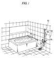
- FIG. 1 there is shown a bath room equipped with a shower bath system 10 according to the invention.
- the system 10 includes a hand-held shower unit 12 according to the first embodiment of the invention.
- the shower unit 12 is connected to an electrically operated flow control unit 14 through a flexible hose 16.
- the flow control unit 14 is provided with a conventional faucet spout 18 for the floor area.
- the flow control unit 14 includes a cold water inlet 20 connected in the conventional manner to a water supply, not shown, and a hot water inlet 22 connected to a hot water supply, not shown, such as a boiler.
- Conventional flow control valves 24 and 26 operated, respectively, by electric valve actuators 28 and 30 are disposed across the inlets 20 and 22 to control the flow rate therethrough.
- Each of the actuators 28 and 30 may be of the conventional type having a stepping motor which is controlled by an electronic control circuit 32.
- the inlets 20 and 22 are merged into a common pipe 34 so that the valves 24 and 26 operate as mixing valves for the common pipe 34.
- a conventional thermistor-type temperature sensor 36 and a conventional turbine-driven flowmeter 38 is arranged in the common pipe 34 to detect the temperature and flow rate of mixed water flowing therethrough.
- the common pipe 34 is bifurcated into a first outlet 40 connected to the shower hose 16 and a second outlet 42 connected to the faucet 18.
- Conventional shut-off valves 44 and 46 are provided in the outlets 40 and 42, respectively. Obviously, when the valve 44 is opened with the valve 46 closed, the mixed water under pressure will be fed entirely toward the shower unit 12. If the valve 44 is closed with or without the valve 46 closed, the water pressure to the shower unit 12 will be interrupted. When both valves 44 and 46 are opened, the shower hose 16 will be subjected to a substantial pressure drop.
- These shut-off valves 44 and 46 are operated, respectively, by conventional solenoid actuators 48 and 50 which are controlled by the control circuit 32.
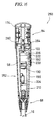
- the hand-held shower unit 12 has a tubular handle casing 52 having a longitudinal axis 54.
- the casing 52 may be made from suitable plastic material and may be comprised of two split halves joined together along a vertical parting plane 56 as will be readily apparent from FIG. 10.
- the handle casing 52 has a water conduit 58 extending therethrough from a first or proximal end 60 to a second or distal end 62 of the casing.
- the water conduit 58 is radially outwardly offset from the longitudinal axis 54 of the casing 52 so that a central cavity 64 having a dimension large enough to house an electric drive 66 and various other components is formed in the handle casing 52.
- the water conduit 58 has an elongated arcuated cross-section extending circumferentially of the casing 52 to provide a large cross-sectional flow area for the water flow flowing therethrough.
- the coupling assembly 68 includes a hose joint 70 provided with a serrated tubular section 72 over which an end of the hose 16 is fitted and secured by a collet ring 74.
- the joint 70 has an upper boss 76 which is fluid tightly and rotatably fitted in an associated bore of the casing 52 by way of suitable sealing means such as O-rings.
- the hose joint 70 is held in place by a retainer nut 78 screwed to the casing 52 in such a manner that an annular space 80 is formed between the lower end of the casing 52 and an annular end face 82 of the joint 70.
- a plurality of passages 84 extend across the joint 70 to communicate the interior of the flexible hose 16 to the annular space 80. Accordingly, water fed by the hose 16 will flow through passages 84 and annular space 80 into the water conduit 58.
- a Y-packing 86 fitted over the joint 70 establishes a fluid seal while permitting the hose joint 70 to rotate with respect to the retainer nut 78 and to the handle casing 52.
- Rotation of the hose joint 70 with respect to the casing 52 is limited by a stop pin 88 projecting from the joint 70 and engaging in an arcuated groove 90 formed on the lower end of the casing 52.
- the groove 90 is discontinued at 92 to form a stop wall against which the stop pin 88 is engageable.
- the hand-held shower unit 12 is fluid tightly swivelled to the flexible hose 16 for limited rotational movement having a rotational angle of less than 360°.
- Such arrangement for limited rotation is particularly advantageous in providing a high degree of freedom of relative rotation for the shower unit 12 with respect to the flexible hose 16, while preventing electric wires connecting the shower unit 12 and the flow control unit 14 from being overly twisted as described later in more detail.
- Water under pressure admitted in the water conduit 58 is supplied to a rotatable shower head 94 by way of a friction-free or contact-free sealing arrangement which will now be described.
- the second or distal end 62 of the handle casing 52 is comprised of a circular end plate 96 bonded to a radial wall 98.
- the end plate 96 is formed with a stepped axial bore 100 which opens into a larger bore 102 which is offset with respect to the longitudinal axis 54 of the handle casing 52.
- a pressure responsive movable sealing member 104 is fluid tightly and slidably received in the bores 100 and 102 of the end plate 96.
- the movable sealing member 104 comprises a disk-shaped upper portion 106 and a cylindrical lower portion 108, with the former engaging in the offset bore 102 and the latter in the axial bore 100.
- An O-ring 110 provides a fluid tight seal between the bore 102 and the upper portion 106, while an O-ring 112 serves to seal the lower portion 108 with respect to the bore 100.
- the upper portion 106 of the movable sealing member 104 has an elongated water outlet port 114 which is offset from the longitudinal axis 54 of the casing 52 and opens into the planar end face 115 of the sealing member 104.
- the outlet port 114 is in fluid communication with a similarly elongated through opening 116 which is formed in the end plate 96 and which opens into a D-shaped groove 118 which, in turn, is communicated with the water conduit 58.
- water will flow from the conduit 58 through the groove 118 and the opening 116 into the water outlet port 114.
- the movable sealing member 104 is provided with a through bore 120 coaxial with the handle casing 52.
- a shaft 122 extends through this bore 120 as best shown in FIGS. 3, 9A and 9B.
- the rotatable shower head 94 is detachably fastened by a screw 124 to the outer end of the shaft 122.
- the rotatable shower head 94 has a planar end face 126 perpendicular to the longitudinal axis 54 and closely facing the planar end face 115 of the sealing member 104 and the upper end face 128 of the end plate 96.
- the shaft 122 is rotatably supported by the sealing member 104 which, in turn, is movably supported by the end plate 96 for limited axial movement.
- a Y-packing 130 (FIGS. 9A and 9B) is used to seal the shaft 122 against the sealing member 104.
- the rotatable shower head 94 is cylindrical in shape and coaxially aligned with the handle casing 52.
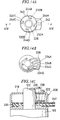
- the rotatable shower head 94 is provided with four spray or water delivery heads 132, 134, 136 and 138 having different spray or water delivery characteristics.
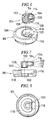
- the spray head 132 includes an outlet fitting 140 having perforations 142 adapted to spray water in the form of a normal diverging spray 144.
- the next spray head 134 is provided with an outlet fitting 146 having an enlarged single discharge opening 148 adapted to deliver a non-restricted laminar flow 150. This configuration is advantageous when water is to be delivered at a higher flow rate such as feeding a bath tub or wash basin.
- the third spray head 136 is designed to form an anti-splash aerated or frothed spray 152 and, to this end, has an outlet fitting 154 provided with air inlets 156 that are merged into venturi-forming discharge openings 158.
- the fourth spray head 138 is provided with an outlet fitting 160 having a plurality of discharge passages 162 which are converged toward a point to form converged water jets 164 which may be used to provide massaging effect.
- These outlet fittings 140, 146, 154 and 160 are in fluid communication, respectively, with water inlets 166, 168, 170 and 172 having an oblong cross-section and which are open onto the end face 126 of the shower head 94. As will be best understood from FIGS.
- these inlets 166, 168, 170 and 172 are radially offset from the axis 54 of the handle casing 52 so that, upon rotation of the rotatable shower head 94, they are aligned in sequence with the water outlet port 114 of the movable sealing member 104 to receive water under pressure therefrom.
- the rotatable shower head 94 is preferably surrounded by a cap 174 detachably fitted over the handle casing 52 and having a window 176 aligned circumferentially with the outlet port 114.
- the shaft 122 carrying the rotatable shower head 94 is provided with a shoulder 178 formed by a D-cut.
- the shower head 94 is seated on the shoulder 178 and is held in place by the screw 124 (FIG. 3).
- an adjustable flanged nut 180 is threadingly engaged over the shaft 122 and abuts against the inner surface 182 of the end wall 98.
- the surface 182 provides a bearing surface for the flanged nut 180 as the shaft 122 is rotated by the electric drive 66.
- an O-ring 184 is fitted in a groove formed on the end face 115 of the sealing member 104 and surrounding the water outlet port 114.
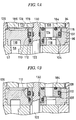
- the flanged nut 180 is adjusted in such a manner that the lower end face 126 of the head 94 closely faces the upper end face 115 of the movable sealing member 104, with a small clearance in the order of a fraction of a millimeter being formed therebetween as shown exaggerated in FIG. 9A, and that the lower end face 126 of the rotatable shower head 94 loosely contacts with the O-ring 184.
- the shower unit 12 may be controlled such that the shower head 94 is rotated when the pressure of water in the water conduit 58 is absent or less than a predetermined level.
- the movable sealing member 104 rests upon the end plate 96 as shown in FIG. 9A and, although not shown in FIG. 9A, the rotatable shower head 94 loosely engages the O-ring 184.
- the weight of the shower head 94 and the shaft 122 as assembled together, as well as the weight of the electric drive 66 suspended therefrom, are supported by the O-ring 184 which is then slightly compressed.
- the rotatable shower head 94 is free from any frictional contact with the stationary parts of the shower unit 12 other than the O-ring 184, the rotatable shower head 94 can be rotated readily even when the electric drive 66 is comprised of a micromotor having a limited output.
- the upper face of the plate 96 may be recessed as shown at 186 in FIG. 6.
- the sealing member 104 has, in the bore 102 in which it is fitted, a pressure receptive cross-sectional area which is equal to the cross-sectional area of the O-ring 110 minus the cross-sectional area of the O-ring 184 and minus the cross-sectional area of the O-ring 112.
- the net cross-sectional pressure receptive area of the sealing member 104 is shown hatched in FIG. 6.
- the movable sealing member 104 is subjected to an upward thrust due to the pressure difference acting on the pressure receptive area. As a result, the sealing member 104 is biased against the rotatable shower head 94 to compress the O-ring 184 as shown in FIG. 9B, thereby establishing a fluid tight seal therebetween. In this manner, the movable sealing member 104 enables to reduce frictional engagement between the rotatable shower head 94 and the casing 52 during rotation of the head 94 but to establish an fluid tight seal therebetween whenever water is being supplied.
- the electric drive 66 comprises a conventional geared micromotor 188 having a DC motor 190 and a reduction gear mechanism 192.
- the final gear, not shown, of the reduction gear mechanism 192 is coupled to the shaft 122 in a well known manner.
- the micromotor 190 is controlled by an electronic control circuit 194 mounted on a circuit board 196 which is also received in the inner cavity 64 of the handle casing 52 and affixed thereto.
- the geared micromotor assembly 188 primarily is supported by and suspended from the shaft 122.
- the housing of the reduction gear mechanism 192 is provided with a pair of radial webs 198 which are sandwiched between the casing halves as shown in FIG. 10. With this arrangement, the geared micromotor assembly 188 may readily be assembled to the shaft 122 with a high degree of alignment, regardless of fabrication tolerances that might exist.
- the shower unit 12 is provided with a pair of conventional push-button-type control switches 200 and 202 which are connected to the control circuit 194 by electric wires, not shown.
- the upper control switch 202 is intended to control water supply to the shower unit 12 by sending a command to open or close the flow control valves 24 and 26, whereas the lower control switch 200 is used to control the spray or water delivery characteristics by sending a signal to rotate the rotatable shower head 94.
- a conventional pressure sensor 204 is operatively associated with the water conduit 58 to detect the pressure of water flowing therethrough and its output signal is sent via signal lines, not shown, to the control circuit 194.
- the shower unit 12 is further provided with an angular position sensor 206 which is associated with the shaft 122 and which delivers signals to the control circuit 194 via signal lines, not shown.
- the position sensor 206 will be described later in some detail with reference to FIGS. 14A-14C.
- electric power is supplied from the control circuit 32 of the flow control unit 14 to the control circuit 194 of the shower unit 12 via a pair of supply lines 208 having a connector 210 as shown in FIGS. 3 and 12.
- the control circuits 32 and 194 preferably comprise programmable digital microcomputers which communicate with each other via a pair of twist wires 212 similarly shown in FIG. 12 and having a connector 214. As shown in FIGS.
- the lines 208 and 212 are helically wound around the flexible shower hose 16.
- the portion of these lines 208 and 212 extending out of the hose 16 extends through a pair of inclined passages 216 formed across the hose joint 70 and opening into a central bore of the boss 76 as shown in FIGS. 3 and 12.
- the lines 208 and 212 are drawn into the central cavity 64 of the handle casing 52.
- the wires 208 and 212 are substantially exempted from tension and stress throughout the swivelling motion of the shower unit 12.
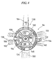
- the angular position sensor 206 is designed to detect which one of the four spray heads 132, 134, 136 and 138 of the rotatable shower head 94 is aligned with the water outlet port 114 of the handle casing 52, as well as to detect a timing at which the DC motor 190 must be braked to correctly position the spray heads.
- the position sensor 206 may be comprised of a combination of five limit switches of the conventional type associated with the shaft 122.
- the sensor 206 includes a housing 218 to which is secured a stationary contact plate 220 provided with a printed pattern forming fixed contacts.
- the fixed contacts printed on the plate 220 cooperate with three rotary contacts 222,224 and 226 mounted to a rotary blade 228 fastened by a screw 230 to the shaft 122 for rotation therewith.
- the printed pattern includes four fixed contacts 232A-232D which are soldered to terminals 234A-234D, respectively, and which cooperate with the movable contact 224.
- the inner circular fixed contact 236 which is soldered to a terminal 238 is in permanent contact with the movable contact 226 and provides a ground potential.
- the fixed contact 232A is engaged by the movable contact 224 so that the first limit switch 239A consisting of the fixed contacts 232A and 236 and the movable blade 228 is closed whereby the first spray head 132 is detected.
- the second limit switch 239B consisting of the fixed contacts 232B and 236 and the movable blade 228 is closed whereby the second spray head 134 is detected.
- the third and fourth limit switches 239C and 239D including, respectively, the fixed contacts 232C and 232D will be closed in the similar manner as the head is rotated.
- the printed pattern also includes an outer fixed contact 240 leading to a terminal 242.
- This contact 240 has four narrow inwardly-directed projections 244A-244D which cooperates with the movable contact 222 to form the fifth limit switch 239E.
- the fifth limit switch is intended to detect the precise angular position at which, during rotation, the rotatable shower head 94 must be stopped. Therefore, the control circuit 194 is programmed such that, upon receipt of a signal from the fifth switch, it reverses electric current fed to the DC motor 190 to produce braking effect as well known in the art.
- FIGS. 15 and 16 illustrate a modified form of the shower unit.
- the modified shower unit 250 differs from the shower unit 12 described hereinbefore in that, to facilitate assemblage of components, the handle casing is divided into an inner and an outer casing and that the movable sealing member is imparted an enlarged pressure receptive area to increase the sealing pressure. Parts and members similar to those described hereinbefore are indicated by like reference numerals and need not be described again.
- the handle casing 252 comprises an outer casing 254 and an inner casing 256 which is detachably fitted in the outer casing 254.
- the water conduit 58 extends through the inner casing 256 and opens into an axial bore 258 in which a movable sealing member 260 is slidably fitted and sealed by a Y-packing 262.
- the movable sealing member 260 is equivalent in function to the movable sealing member 104 of the first embodiment 12 and is provided with a water outlet port 264 with which the water inlets of different spray heads are selectively aligned.
- An O-ring 266 is similarly used around the outlet port 264 to provide a fluid tight seal between the movable sealing member 260 and the rotatable shower head 94.
- the movable sealing member 260 has a cross-sectional pressure receptive area which is close to the largest cross-sectional area of the handle casing 252. Accordingly, when the shower unit 250 is in use, an increased fluid tightness is established.
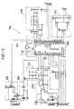
- the electronic control circuit 194 for the hand-held shower units 12 and 250 and the electronic control circuit 32 for the flow control unit 14 may comprise programmable digital microcomputers 300 and 302, respectively.
- the control circuit 32 includes a power circuit 304 fed, for example, by a battery 306 received in the flow control unit 14.
- the battery 306 also feeds a voltage regulator 308 of the control circuit 194 through electric lines 208 which are wound around the flexible hose 16 as described before.
- the microcomputer 300 includes a central processing unit (CPU) 310 which accesses the position sensor 206, the control switches 200 and 202 and the pressure sensor 204, through an input and output interface (I/O) 312.
- CPU central processing unit
- the CPU 310 controls the DC micromotor 190 via a motor driver circuit 314 to rotate and control the rotatable shower head 94 as described later with reference to flowcharts.
- the microcomputer 302 includes a CPU 316 and an I/O 318.
- the CPU 316 accesses the mixed water temperature sensor 36, the flowmeter 38 and a power control switch 320 through the I/O 318.
- the CPU 316 controls the solenoid actuator 48 for the shower valve 44, the solenoid actuator 50 for the faucet valve 46, the stepping motor 28 of the flow control valve 24 for cold water line, and the stepping motor 30 of the flow control valve 26 for hot water line, respectively, through driver circuits 322, 324, 326 and 328, as described later.
- the CPU 316 further controls a liquid crystal display (LCD) 330 and operates an alarm buzzer 332 via driver 334.
- LCD liquid crystal display
- the microcomputers 300 and 302 transmit and receive digital data and instructions with each other via wire lines 212. Communication is performed according to asynchronous serial data communication mode. To this end, instructions and information transmitted from the microcomputer 300 is input through a transceiver described later into an interrupt input terminal of the microcomputer 302 for processing with the topmost priority. Similarly, commands and signals transmitted from the microcomputer 302 is applied to an interrupt terminal of the microcomputer 300 for prompt processing. Since in this manner communication between the microcomputers 300 and 302 is performed digitally, it is possible to communicate data and instructions with only a pair of signal lines 212. Use of such limited number of signal lines is advantageous in providing the hose 16 with a high degree of flexibility.
- FIG. 18 there is shown a wiring diagram to enable those skilled in the art to implement the control circuit 194 shown in FIG. 17.
- a commercially available 8-bit single-chip microcomputer M34225 marketed by Mitsubishi Electric Corporation of Tokyo, may be used as the microcomputer 300 shown in FIG. 17.
- Asynchronous serial communication signals are transmitted from the microcomputer 300 via a transceiver 336. Signals from the other microcomputer 302 are received through a receiver 308 and transferred to the interrupt terminal of the microcomputer 300. Output from the pressure sensor 204 is forwarded to the microcomputer 300 via an amplifier compensator circuit 340.
- Voltage circuit 342 supplies a reference voltage for the pressure sensor 204.
- Connector indicated by the reference numeral CN3 connects the microcomputer 300 to the above-mentioned five limit switches of the position sensor 206.
- a voltage monitor circuit 344 monitors the voltage controlled by the regulator 308.
- the signals from the spray pattern control switch 200 and water supply control switch 202 are fed through a connector indicated by the reference symbol CN5.
- the DC motor 190 for rotating the rotatable shower head 94 may be connected to the driver circuit 314 through a connector referenced at CN4.
- FIG. 19 is a wiring diagram to enable those skilled in the art to implement the control circuit 32 shown in FIG. 17.
- a 8-bit single-chip microcomputer M37410M6H commercially available from Mitsubishi Electric Corporation, is used to implement the microcomputer 302. Communication with the microcomputer 300 for the shower unit is performed through a transmitter 346 and a receiver 348.
- the voltage of the power circuit 304 is monitored by a voltage monitor circuit 350 including an integrated circuit MB3773 available from Fujitsu Limited.
- Driver circuits 326 and 328 may be arranged as shown to control the stepping motors 28 and 30, respectively.
- Drivers 322 and 324 may be connected, respectively, to the solenoids 48 and 50 via a connector indicated at CN1.
- output from the temperature sensor 36 is transferred to the microcomputer 302 through a connector indicated by the reference numeral CN3.
- Output pulses from the turbine-driven flowmeter 38 is processed by a wave-shaping circuit 352.
- the CPU 310 of the shower unit control circuit 194 and by the CPU 316 of the flow control circuit 32 The CPU'es 310 and 316 are so programmed as to perform functions described below.
- the CPU 316 of the flow control unit 14 functions for every 15 ms, for example, as shown in FIG. 20.
- the current conditions of the unit 14 are read out by checking various sensors associated with the flow control unit 14, such as flowmeter 38, power control switch 320, temperature sensor 36 for the mixed water. Positions of the shower valve 44 and the faucet valve 46 may be ascertained by checking the driver circuits 322 and 324.
- the desired angular position of the rotatable shower head 94 as addressed by the user and stored in the memory is also checked. As described later, the desired head position is altered one by one in sequence as the spray pattern control switch 200 is operated. The obtained information is saved at function 402.
- the CPU 310 of the shower unit 12 functions for every 15 ms, for example, to renew the current shower head conditions.
- the present conditions of the shower unit 12 are read out by checking the position sensor 206, pressure sensor 204, spray pattern control switch 200 and water supply control switch 202. The information is saved at function 404 for subsequent use.
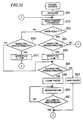
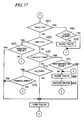
- FIGS. 22 and 23 are primarily intended to perform data communication between the CPU'es 310 and 316. Procedures shown in FIG. 22 may be carried out by the CPU 316 for every 125 ms, for example.
- the interrupt routine shown in FIG. 23 is commenced whenever function 413 or 414 is performed.
- the CPU 316 reads out the control unit information at point 411 and at function 412 determines if the faucet valve 46 is open. If open, the water from the conduit 34 will be being drained to the faucet 18 so that the water pressure applied via the shower hose 16 to the shower unit 16 will disappear or at least will be reduced. As described hereinbefore, this is a preferred pressure condition for rotating the rotatable shower head 94 without undergoing rotational friction.
- the CPU 316 sends to the CPU 310 a permission indicating that the shower head can be rotated, together with an information indicative of the desired angular position for the shower head 94. If the faucet valve is closed, the CPU 316 sends a rotation inhibition at function 414. As mentioned before, transmission 413 or 414 is directed to the interrupt input of the CPU 310. Therefore, in response to transmission 413 or 414, the CPU 310 immediately commences the interrupt routine of FIG. 23 to accept transmission at function 431 and save it at function 432.
- the CPU 316 sends an information request to the CPU 310 which responds at function 433 to receive it and to read the shower unit information at function 434 and transmits it to the CPU 316 at function 435 via the signal lines 212.
- the CPU 316 determines at function 417 if the pattern control switch 200 is pressed on by the user. If pressed on, the desired angular position for the rotatable shower head 94 is renewed at function 418 in such a manner that a next spray head is addressed. Then, the CPU 316 determines at function 419 whether the water supply control switch 202 is pressed on. The control switch 202 cooperates with the memory of the CPU 316 to function as a toggle switch.
- the CPU 316 operates at functions 420-422 to change over a flag which is stored in its memory to indicate the user's instructions.
- Flag “1” may be used to represent an instruction that water should be supplied to the shower unit 12, with flag "0” indicating that water supply must be interrupted. This flag is used during flow rate control as described later with reference to FIG. 26.
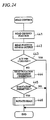
- functions shown therein may be performed periodically by the CPU 310 of the shower unit 12, for example, for every 2 ms.
- the addressed position for the rotatable shower head 94 is read out from the memory of the CPU 310 and at function 442 the position sensor output is retrieved from the memory.
- Function 443 determines whether the actual angular position of the shower head 94 is in commensurate with the addressed position. If not, permission or inhibition of rotation is read out at function 444 and a decision is made at function 445 to see whether rotation is permitted.
- the rotatable shower head 94 is rotated at function 446 if rotation is permitted.
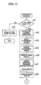
- the CPU 316 performs functions shown in FIG. 25 to control various valves including shut-off valves 44 and 46 and flow control valves 24 and 26.
- the functions of FIG. 25 may be commenced for every 250 ms, for example.
- Information concerning the flow control unit 14 and the shower unit 12 is read out at functions 451 and 452, respectively.
- the CPU 316 determines at function 453 whether the current angular position of the rotatable shower head 94 is equal to the desired position addressed by the user. If equal, the solenoid 48 is signalled to open the shower valve 44 at function 454 and the solenoid 50 is signalled to close the faucet valve 46 at function 455, to supply mixed water to the shower unit 12.
- the faucet valve 46 is opened at function 456 and the shower valve 44 is closed at 457 thereby to interrupt water supply to the shower unit 12. Thereafter the CPU 316 proceeds to the flow rate control functions which is shown in FIGS. 26 and 27 in a greater detail.
- FIGS. 26 and 27 Functions shown in FIGS. 26 and 27 are intended to control the flow rate of water through the flow control valves 24 and 26 in accordance with the water pressure detected by the pressure sensor 204.
- Control of flow rate in response to the pressure in the water conduit 58 of the shower unit 12 is preferable because the detection of the pressure variation by the pressure sensor 204 is carried out much faster than the conventional flowmeter 38 having a turbine which requires a certain time lag before it reaches the steady state revolution.
- Desirable flow rate may vary depending on the spray pattern of the spray heads 132, 134, 136 and 138. For example, the spray head 136 for an aerated spray requires a relatively high flow rate, whereas the spray head 138 for the converged jets must be operated at a lower flow rate in order to prevent injury.
- Flow rate control is conducted in such a manner that a "desired” flow rate for the selected spray head is first determined. Then a hypothetical “measured” flow rate is derived based on the pressure sensor output. The flow control valves 24 and 26 are controlled such that the measured flow rate becomes equal to the desired flow rate. Output from the flowmeter 38 may be used as representing the "actual” or “true” flow rate as described later.
- Q the measured flow rate
- K a constant
- Cv a flow coefficient unique to the selected particular spray head
- P a gauge pressure detected by the pressure sensor 204.
- the values of flow coefficient Cv for the spray heads 132, 134, 136 and 138 have been empirically determined and stored in the memory of the CPU 316 as a table which is shown in FIG. 28, wherein the suffix M represents generally the symbols A-D for the four spray heads.
- the flow coefficient Cv to be stored as the table of FIG. 28 may be determined for each of the spray heads 132, 134, 136 and 138 by operating the shower unit while measuring the revolutionary speed of the flowmeter 38 and the actual voltage output of the pressure sensor 204.
- the flag is checked to see if water supply is desired. If the flag is "0" indicating that water supply is not needed, at function 462 the stepping motors 28 and 30 are driven to fully close both of the flow control valves 24 and 26. If the flag is "1" indicating that water supply to the shower unit 12 is needed, control of the flow control valves 24 and 26 is permitted at function 463. Then at function 464 the output pulses from the turbine-driven flowmeter 38 are input and the revolutionary speed N of the flowmeter is calculated based on the interval between pulses in the well known manner. Function 466 looks-up the table shown in FIG. 28 to see the value Cv of the selected spray head.
- the expected output voltage V Q which is anticipated as being issued from the pressure sensor 204 when the flow rate is equal to Q, is computed according to equation (2).
- the table is looked up to see the desired pressure sensor output voltage V M which corresponds to the desired flow rate for various spray heads.
- the desired flow rate may be in the range of 7-13 liters per minute for the normal spray, 10-16 liters per minute for the non-restricted flow, 9-15 liters per minute for the aerated spray, and 5-11 liters for the converged spray.
- the values V M of the desired pressure sensor output voltage corresponding to the foregoing desired flow rates have been empirically determined preliminarily and included in the table.
- the CPU 316 determines if the actual pressure sensor voltage Va is equal to or greater than V M plus alpha. If it is, at function 470 the CPU 316 decrements the openings of both flow control valves 24 and 26 proportionally so as to decrease the flow rate. If it is not, then function 471 determines whether the actual pressure sensor voltage Va is equal to or smaller than V M minus alpha. If it is, at function 472 the CPU 316 increments the openings of both flow control valves 24 and 26 proportionally so as to increase the flow rate.
- the CPU 316 compares the expected pressure sensor voltage V Q with the minimum allowable voltage V ML and the maximum allowable voltage V MH stored in the table to confirm whether the actual flow rate is in a allowable range. If it is not, an alarm is done at function 474 by energizing the buzzer 332 and an LED and at function 475 the valves 24 and 26 are fully closed. If in the allowable range, then at function 476 the error between Va and V Q is calculated to determine the deviation of the pressure sensor output from the flowmeter output. Then at function 477 it is determined whether the detected error is less than a permissible range. If not, it is determined that the flow coefficient C VM of the table of FIG.
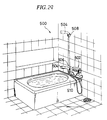
- FIG. 29 illustrates a shower bath arrangement according to the second embodiment of the invention.
- the shower unit is designed such that, in addition to the manual spray pattern control function described hereinbefore, the spray heads are automatically rotated and selected to change over the spray or water delivery characteristics in response to the position in which the shower unit is situated.
- the shower bath system 500 includes a flow control unit 502 which is similar to the flow control unit 14 described above.
- a shower unit 504 is similar in principle and structure to the shower unit 12 or 250 described before, except that it is adapted to cooperate with a pair of shower hangers 506 and 508 fixed on the wall of the bath room.
- the first or lower hanger 506 is located in the vicinity of the bath tub 510 so that mixed water flowing out of the shower unit 504 as hanged on the first hanger 506 is poured into the bath tub through a short distance of fall.
- the second or upper hanger 508 may be situated at some higher location.
- the hanger 506 has a positioning recess 512 which is adapted to mate with an associated positioning projection 514 formed on the handle casing 516 of the shower unit 504. It will be understood that due to the presence of the positioning arrangement, the shower unit 504 will be placed at a fixed orientation.
- the shower unit 504 is provided with a pair of magnetically-operated normally-open reed switches 518 and 520 which are spaced apart at both sides of the projection 514.
- a first permanent magnet segment 522 is provided on the inner wall of the hanger 506 in registration with the reed switch 518. Referring to FIG.
- the second hanger 508 is similarly provided with a positioning recess 524 cooperating with the positioning projection 514 of the handle casing 516.
- the second hanger 508 has a second permanent magnet segment 526 which magnetically cooperates with the second reed switch 520 of the shower unit 504.
- reed switches 518 and 520 are connected to the control circuit of the shower unit 504 which may be identical to the control circuit 194 described before.
- the wiring arrangement may be such that the CPU 310 accesses the reed switches 518 and 520 through the I/O interface 312.
- the control circuit 32 described above may be used with minor modification in program which will be described below with reference to FIG. 32.
- Functions described with reference to the flowcharts shown in FIGS. 20-27 may be modified to the extent that the CPU 310 of the shower unit 504 transmits to the CPU 316 of the flow control unit 502 an information concerning the position of the reed switches 518 and 520 and that between functions 416 and 417, functions 531-534 shown in FIG. 32 are performed.
- the CPU 316 determines if the first reed switch 518 is closed. Closure of the first switch 518 means that the shower unit 504 is hanged on the lower first hanger 506.
- the CPU 316 alters the desired angular position for the rotatable head 94 in such a manner that the spray head 134 for the non-restricted flow pattern is selected.
- the head is rotated to the aimed angular position, mixed water will supplied in the form of non-restricted flow 150 illustrated in FIG. 4.
- Water supply in this flow mode is advantageous when feeding the bath tub 510 through the shower unit 504, because a columnar flow of water issuing from the enlarged single discharge opening 148 is less likely to be cooled during fall. Therefore, a conventional faucet for the bath tub may be omitted and the hand-held shower unit 504 of the invention may be used also for the purpose of feeding the bath tub.
- the CPU 316 may be programmed such that it monitors via the flowmeter 38 the quantity of water being fed to the bath tub and that water supply is automatically terminated when the measured quantity of water becomes equal to a predetermined quantity.
- the CPU 316 checks the second reed switch 520 to see if it is closed. If it is, meaning that the shower unit 504 is hanged on the upper second hanger 508, then the CPU 316 changes the desired position so that the spray head 132 adapted to normal spray is addressed. As the rotatable shower head 94 is rotated to the addressed position, water will be delivered in a normal diverging spray pattern. In this manner, the spray or water delivery pattern is automatically switched over depending on the position at which the shower unit is hanged.
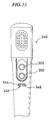
- FIG. 33 illustrates another form of the shower unit which may be used in the shower bath system 500 described above in place of the hanger-sensing shower unit 504.
- the shower unit 540 may be identical to the shower unit 12 or 250 described before, except that a conventional optical distance sensor 542 is provided in addition to the manual control switches 200 and 202.
- Optical distance sensors suitable for the purposes of the present invention are commercially available from various sources and includes the position sensitive distance detector available from Sharp Corp. of Osaka.
- Such distance sensor includes a collimator lens 544 through which near infrared radiation emitted by an LED, not shown, is forwardly projected. Radiation reflected by the shower bather is collected by an objective 546 and an image is focused on a linear photosensor, not shown.
- the sensor 542 is designed such that the dimension of the image focused on the photosensor varies according to the distance between the object and the sensor 542 so that the photosensor issues varying output in response to the distance.
- the output of the distance sensor 542 is read out by the CPU 310 of the control circuit 194 and is transferred to the CPU 316 of the control circuit 32 in the similar manner as described before.
- the CPU 316 may be programmed to rotate the spray head of the shower unit 540 such that an aerated anti-splash spray is delivered when a relatively short distance is sensed, a normal diverging spray is delivered when a medium distance is sensed, and a non-restricted flow is delivered when a relatively long distance is sensed.
- the faucet 600 includes faucet body 602 incorporating a conventional single-lever mixing valve 604 as connected by an inlet fitting 606 to sources of cold water and hot water.
- An outlet fitting 608 having a water passage 610 is swivelled at 612 to the faucet body 602 in the conventional manner.
- the fitting 608 has a valve seat 614 formed across the passage 610 which is opened and closed by a conventional latching-type pilot-operated solenoid valve assembly 616.
- the faucet 600 further includes a faucet spout 618 threadingly connected fluid tightly to the outlet fitting 608.
- the faucet spout 618 is generally similar in structure and principle to the shower unit 12 or 250 described hereinbefore, except for the points described below. Therefore, parts and members equivalent to those described before will be indicated by like reference numerals and will not be described again.
- the faucet spout 618 may includes a rotatable water delivery head 620 which is adapted to deliver water in, for example, three different water delivery patterns including an aerated anti-splash spray, a non-restricted flow and a non-aerated normal spray. Modifications to be rendered on the rotatable spray head 94 and the associated angular position sensor 206 described above to design the three-pattern delivery head 620 would be obvious for those skilled in the art from the foregoing description and detailed explanation would not be needed. Selection of water delivery pattern may be made both in manual and automatic modes.
- a mode control switch 622 is provided in addition to a manual delivery pattern control switch 624 to enable the user to select the desired mode at its own volition.
- the water delivery pattern is automatically switched over in response to the distance between the rotatable head 620 and the object under the faucet, such as dishes and vegetables.
- an optical distance sensor 626 similar to that described with reference to FIG. 33 is provided at the second end 62 of the faucet spout 618.
- An electronic control circuit 628 is similarly housed in the inner cavity 64 of the casing 52.
- a battery 630 in the cavity 64 is adapted to supply electric power to the control circuit 628 as well as to the latching-type solenoid valve 616.
- the control circuit 628 includes a microcomputer 632, with a CPU 634, which may be implemented by the M34225 chip described above.
- the CPU 634 accesses through an I/O 636 the control switches 622 and 624, the distance sensor 626 and an angular position sensor 638 associated with the shaft 122, controls the motor 190 through a driver circuit 640, and controls the solenoid valve 616 via an amplifier circuit 642 in the following manner.
- FIGS. 36 and 37 there are shown functions performed by the CPU 634 to control the faucet 600.
- the microcomputer 632 independently controls the faucet 600. Therefore, the functions shown may be performed continuously as long as the battery 630 is alive.
- a flag indicating the mode of operation of the faucet 600 is set to "1" and the solenoid valve 616 is closed.
- flag "1" may be used to represent the automatic mode wherein water delivery pattern is to be determined automatically in response to output from the distance sensor 626, whereas flag "0" may be used to indicate that a manual selection of delivery pattern is desired.
- present conditions of the faucet are read out by accessing to the switches 622 and 624, the angular position sensor 638 and the distance sensor 626.
- Functions 653-657 are performed to ensure that the mode control switch 622 operates as a toggle switch, meaning that the mode is changed over alternately each time the switch 622 is pressed on.
- the CPU 634 checks the mode control switch 622 to see if it is pressed on. If pressed upon, indicating that the mode is now to be switched over, then at function 655 the mode indicator flag is changed to "0". If not pressed upon, indicating that the mode is now automatic and that no mode change is necessary, then the CPU 634 proceeds to functions shown in FIG.
- the CPU 634 checks the manual pattern control switch 624 to see if it is actuated. It not actuated, the solenoid valve 616 is kept open. If the switch 624 is actuated, indicating that the user is now desiring that the water delivery pattern of the faucet 600 be changed, then at function 659 the valve 616 is closed to ensure that water pressure in the water conduit 58 disappears and that the rotatable water delivery head 620 is smoothly rotated without undergoing rotational friction by the movable sealing member 260.
- the CPU 634 signals at function 660 to rotate the DC motor 190 and awaits at function 661 until the rotatable head 620 is rotated to the next angular position. If rotation is completed, then the CPU returns to repeat function 652.
- the CPU 634 may be programmed such that an aerated anti-splash spray pattern is selected when a long distance is sensed, a non-restricted flow pattern is addressed when a mid range distance is detected, a non-aerated normal spray pattern is used when a short distance is sensed, and the valve 616 is closed if no object is sensed within a predetermined range.
- the distance may be defined, for example, as being short if it is less than 100 mm (L MIN ), middle for a range between 100 mm and 250 mm (L MID ), long for a range between 250 mm and 400 mm (L MAX ).
- the CPU 634 determines at function 663 whether the distance Ld detected by the distance sensor 626 is greater than the higher limit L MAX . If so, the valve 616 is checked at function 664 and is closed at function 665 if it is open. In this manner, the valve 616 is automatically closed if no object is sensed within the maximum range. If the detected distance Ld is equal to or less than L MAX , then at function 666 it is determined if Ld is greater than L MID . If it is, meaning that the object is in the long distance range, then the CPU checks the output of the position sensor 638 at function 667 to see whether the present water delivery pattern is aerated.
- the solenoid valve 616 is closed at function 668 and the motor 190 is activated at function 669. These functions are cyclically repeated until the rotatable head 620 is rotated to the aerated spray position. If at function 666 it is determined that the detected distance Ld is less than L MID , then function 670 checks if Ld is greater than L MIN . If it is greater, indicating that the object in the mid range, then at function 671 the present position of the rotatable head is checked and, if the position is not for the non-restricted flow, the valve 616 is closed at 668 and the motor is rotated at 669.
- the rotatable head will be rotated until the water discharge head adapted to the non-restricted flow is selected. If the determination at 670 is negative, then at function 672 the CPU 634 determines if Ld is equal to or less than L MIN . If it is, meaning the object is in a short distance range, then the valve 616 is closed at 668 and the motor is rotated at 669 unless at function 673 it is determined that the current position is for the normal spray pattern. In this manner, in the automatic control mode, the rotatable water delivery head is automatically rotated and the water delivery pattern changed over according to the position of the object.
- a conventional electrostatic capacitive sensor may be used to detect the fact that the shower unit is held in the hand of the user. Then, the rotatable shower head may be automatically rotated to deliver water in the form of a normal spray.
Claims (41)
- Dispositif de fourniture d'eau comprenant une unité de délivrance d'eau (12; 250; 504; 540, 618) pourvue d'une tête rotative de délivrance, comprenant :
un boitier tubulaire (52; 252) ayant une extrémité proximale (60) et une extrémité distale (62) et dans lequel s'étend un conduit d'eau (58), ladite extrémité proximale (60) du boîtier étant adaptée pour être reliée à une alimentation en eau pour admettre de l'eau sous pression dans ledit conduit, ladite extrémité distale (62) dudit boitier définissant une face d'extrémité plane (115), ledit conduit (58) se terminant dans une ouverture de sortie d'eau (114; 264) qui s'ouvre sur ladite face d'extrémité plane (115) et est radialement déportée par rapport à l'axe longitudinal (54) du boîtier; et
une tête de délivrance rotative (94, 620) supportée relativement audit boîtier (52; 252) par un côté de ladite extrémité distale (62) pour pouvoir tourner autour dudit axe longitudinal (54) dudit boîtier, ladite tête de délivrance ayant une face d'extrémité plane (126) dans le même plan que et en liaison à rotation avec ladite face d'extrémité plane (115) dudit boîtier, ladite tête de délivrance (94, 620) possédant une pluralité de pommes d'aspersion différentes (132; 134; 136; 138) également espacées angulairement les unes des autres et ayant des caractéristiques différentes de décharge ou d'aspersion, chacune desdites têtes d'aspersion ayant une entrée d'eau (166; 168; 170; 172) et une sortie d'aspersion dirigée radialement vers l'extérieur (140; 146; 154; 160) en communication fluidique avec ladite entrée d'eau (166; 168; 170; 172),
caractérisé en ce que
ladite face d'extrémité plane (115) est perpendiculaire à l'axe longitudinal (54) dudit boîtier, ledit conduit (58) étant déporté radialement par rapport à l'axe longitudinal (54) du boîtier d'au moins une certaine distance par rapport à celui-ci pour laisser place dans ledit boîtier à une cavité radialement centrale (64) adjacente à ladite extrémité distale (62),
ladite tête de délivrance est supportée relativement audit boîtier (52; 252) par le côté de ladite extrémité distale opposé à ladite cavité centrale (64);
ladite entrée d'eau (166; 168; 170; 172) s'ouvre sur ladite face d'extrémité (126) de ladite tête de délivrance (94, 620) et est déportée radialement par rapport à l'axe longitudinal (54) dudit boitier d'une distance égale à la distance de déport de ladite ouverture de sortie d'eau (114; 264);
un organe moteur électrique (66) est logé dans ladite cavité centrale (64) dudit boîtier et a une sortie en liaison d'entraînement avec ladite tête de délivrance (94, 620) pour la faire pivoter lorsqu'il est activé;
un moyen (208) est prévu pour alimenter ledit organe moteur électrique (66) en énergie électrique; et
un moyen de commande (194) est prévu pour activer ledit organe moteur électrique (66) pour faire pivoter ladite tête de délivrance (94, 620) de façon que l'une desdites entrées d'eau (166; 168; 170; 172) soit sélectivement alignée avec ladite ouverture de sortie d'eau (114; 264) l'eau sous pression admise dans ledit conduit (58) étant ainsi délivrée par l'une choisie desdites pommes d'aspersion (132; 134; 136; 138). - Dispositif selon la revendication 1, dans lequel un arbre tournant (122) est supporté par ladite extrémité distale (62) du boîtier pour tourner autour dudit axe longitudinal (54) de celui-ci, les extrémités dudit arbre s'étendant longitudinalement des deux côtés de ladite face d'extrémité (115); et la tête de délivrance (94) est montée à une extrémité extérieure dudit arbre (122) pour tourner avec celui-ci.
- Dispositif selon la revendication 1 ou 2, dans lequel ladite unité de délivrance d'eau (12; 250; 504; 540) comprend :
un élément d'étanchéité mobile actionné par pression (104; 260) est reçu de façon étanche aux fluides et à coulissement dans ledit alésage (102; 258), ledit élément d'étanchéité (104; 260) ayant une face d'extrémité extérieure (115) perpendiculaire à l'axe (54) dudit boîtier, ledit élément d'étanchéité (104; 260) ayant une ouverture traversante en communication fluidique avec ledit conduit (58), la face d'extrémité intérieure plane (126) faisant face à ladite face d'extrémité extérieure (115) dudit élément d'étanchéité (104; 260) et dans lequel
ledit organe moteur électrique (66) comprend un micromoteur (190);
ledit élément d'étanchéité (104; 260) a dans ledit l'alésage (102; 258) une surface soumise à la pression plus grande que la surface transversale de ladite ouverture de sortie (114; 264) si bien qu'une pression différentielle dirigée vers l'extérieur se développe sur ledit élément d'étanchéité (104; 260) lorsque de l'eau sous pression est admise dans ledit conduit d'eau (58);
ladite face d'extrémité extérieure (115) dudit élément d'étanchéité (104; 260) est sensiblement désaccouplée en l'absence de pression d'eau dans ledit conduit d'eau (58) de ladite face d'extrémité intérieure (126) de ladite tête de délivrance (94, 620) pour supprimer sensiblement tout contact à frottement entre elles et réduire de ce fait le couple exigé dudit micromoteur (190) pour faire pivoter ladite tête de délivrance (94, 620); et
ledit élément d'étanchéité (104; 260) est poussé vers ladite tête de délivrance (94, 620) sous l'effet de la pression d'eau dans ledit conduit (58) pour presser ladite face d'extrémité extérieure (115) de celui-ci contre ladite face d'extrémité intérieure (126) de la tête de délivrance (94) pour réaliser ainsi une étanchéité aux fluides entre celles-ci. - Dispositif selon la revendication 1, 2 ou 3, dans lequel ladite unité de délivrance d'eau est une unité de douche (12; 250; 504; 540) et ladite tête rotative de délivrance d'eau (94) est une tête de douche.
- Dispositif selon la revendication 4, dans lequel ladite tête de douche rotative (94) est fixée de façon amovible audit arbre (122) pour permettre le remplacement par une autre tête de douche.
- Dispositif selon la revendication 4, comprenant de plus une coiffe (174) fixée à ladite extrémité distale (62) du boitier et entourant ladite tête de douche rotative (94), ladite coiffe ayant une fenêtre (176) en alignement avec ladite sortie d'aspersion (140; 146; 154; 160) de l'une choisie desdites pommes d'aspersion (132; 134; 136; 138).
- Dispositif selon les revendications 3 et 4, dans lequel ladite pomme de douche rotative (94), ledit arbre tournant (122), ledit alésage axial (120) dudit élément d'étanchéité (104; 260) et ledit organe moteur électrique sont alignés axialement.
- Dispositif selon la revendication 7, dans lequel ledit organe moteur électrique (66) est suspendu audit arbre (122).
- Dispositif selon la revendication 4, dans lequel ladite unité de douche comprend de plus un capteur de pression (204) ayant pour rôle de capter la pression de l'eau dans ledit conduit d'eau (58) et d'émettre un signal représentatif de la pression détectée et dans lequel ledit moyen de commande (194) active, en réponse audit signal provenant dudit capteur de pression (204), ledit organe moteur électrique (66) seulement lorsque la pression de l'eau dans ledit conduit (58) est inférieure à une valeur prédéterminée.
- Procédé d'utilisation d'un dispositif tel que défini dans l'une quelconque des revendications 1 à 4, comprenant les étapes consistant à :(a) aligner une entrée d'eau choisie (166; 168; 170; 172) de ladite tête de délivrance rotative (94) avec ladite ouverture de sortie d'eau (114; 264) dudit boîtier;(b) admettre de l'eau sous pression dans ledit conduit d'eau (58) pour délivrer une projection d'eau par l'une choisie desdites pommes d'aspersion (132; 134; 136; 138);(c) réduire la pression de l'eau admise dans ledit conduit d'eau (58);(d) faire activer par ledit moyen de commande (194) ledit organe moteur électrique (66) de façon que ladite tête de délivrance rotative (94) soit tournée d'un angle réalisant l'alignement de l'entrée d'eau (166; 168; 170; 172) de la pomme d'aspersion suivante avec ladite ouverture de sortie d'eau (114; 264); et(e) rétablir la pression d'eau pour délivrer de l'eau d'aspersion par ladite pomme d'aspersion suivante (132; 134; 136; 138).
- Procédé selon la revendication 10, dans lequel l'étape (c) est exécutée en vidangeant l'alimentation en eau.
- Procédé selon la revendication 10 dans lequel l'étape (c) est exécutée en interrompant l'alimentation en eau dudit conduit d'eau (58), et l'étape (e) est exécutée en rétablissant l'alimentation en eau.
- Dispositif selon la revendication 3, dans lequel ledit organe moteur électrique (66) comprend un micromoteur à engrenages (188).
- Dispositif selon les revendications 3 et 4, dans lequel ladite unité de douche comprend de plus un détecteur de position angulaire (206) associé audit arbre (122) pour détecter la position en rotation de ladite tête de douche (94) et dans lequel ledit moyen de commande (194) coopère avec ledit détecteur de position (206) pour aligner sélectivement l'une desdites entrées d'eau (166; 168; 170; 172) de ladite tête de douche rotative (94) avec ladite ouverture de sortie d'eau (114; 264) dudit élément d'étanchéité (104; 260).
- Dispositif selon la revendication 1, 2, 3 ou 4, comprenant de plus un moyen de détection (518/522; 520/526; 542) sensible aux conditions de l'environnement dans lequel fonctionne ladite unité de délivrance (504; 540, 618) pour détecter les caractéristiques d'aspersion désirées dans lesdites conditions, ledit moyen de commande (194) répondant audit moyen de détection (518/522; 520/526; 542) et ayant pour rôle de provoquer une rotation de ladite tête de délivrance (94, 620) de telle sorte qu'une pomme d'aspersion adaptée aux caractéristiques d'aspersion désirées soit sélectivement mise en communication avec ladite ouverture de sortie d'eau (114; 264) du boîtier.
- Dispositif selon la revendication 15, dans lequel ledit moyen de détection (542) comprend un moyen pour mesurer la distance entre ladite tête de délivrance (94) et l'utilisateur.
- Dispositif selon la revendication 15, dans lequel ledit moyen de détection (626) comprend un moyen pour mesurer la distance entre ladite tête de délivrance (620) et un objet.
- Dispositif selon la revendication 16, dans lequel ledit moyen de commande (194) fait pivoter ladite tête de délivrance (94) de façon qu'une pomme d'aspersion conçue pour délivrer une aspersion anti-éclaboussement à mélange d'air soit choisie lorsqu'une distance relativement courte est détectée.
- Dispositif selon la revendication 16, dans lequel ledit moyen de commande (194) fait pivoter ladite tête de délivrance (94) de façon qu'une pomme d'aspersion conçue pour délivrer une aspersion divergente soit choisie lorsqu'une distance moyenne est détectée.
- Dispositif selon la revendication 16, dans lequel ledit moyen de commande (194) fait pivoter ladite tête de délivrance (94) de façon qu'une pomme d'aspersion conçue pour délivrer un jet libre soit choisie lorsqu'une distance relativement longue est détectée.
- Dispositif selon la revendication 15, dans lequel ladite unité de délivrance comprend une unité de douche manuelle (504; 540) et dans lequel ledit moyen de détection (518/522; 520/526) détecte lesdites caractéristiques d'aspersion désirées en coopérant avec des supports de douche (506; 508) disposées respectivement en des endroits différents.
- Dispositif selon la revendication 21, dans lequel ledit moyen de détection (518/522; 520/526) comprend une pluralité de commutateurs à actionnement magnétique (518; 520) disposés sur ledit boitier de poignée (52; 252) en des emplacements différents, lesdits commutateurs à actionnement magnétique (518; 520) étant conçus pour être actionnés sélectivement par des aimants permanents (522; 526) disposés sur différents supports de douche (506; 508).
- Dispositif selon la revendication 1, 2, 3 ou 4, dans lequel ledit conduit d'eau (58) a une section courbe allongée, en vue dans la direction dudit axe longitudinal (54) dudit boîtier, qui s'étend suivant la périphérie dudit boîtier.
- Dispositif selon la revendication 4, comprenant de plus :
une unité de commande d'écoulement (14; 502) située en amont de ladite unité de douche (12; 250; 504; 540) et possédant un passage d'eau qui la traverse pouvant être raccordé à ladite alimentation en eau, ladite unité de commande d'écoulement (14; 502) comprenant de plus une première soupape de commande d'écoulement actionnée électriquement (24/28; 26/30) pour commander l'écoulement de l'eau par ledit passage d'eau, un moyen (306) pour alimenter ladite soupape de commande (24/28; 26/30) en énergie électrique, et un circuit électronique de commande (32) pour commander ladite soupape de commande d'écoulement (24/28; 26/30); et
un tuyau flexible (16) branché entre ladite unité de commande d'écoulement (14; 502) et ladite unité de douche (12; 250; 504; 540) pour alimenter en eau sous pression ledit conduit d'eau (58) de ladite unité de douche (12; 250; 504; 540) lorsque ladite soupape de commande d'écoulement (24/28; 26/30) est ouverte. - Dispositif selon la revendication 24, dans lequel ledit circuit électronique de commande (32) de ladite unité de commande d'écoulement (14; 502) coopère avec ledit moyen de commande (194) de ladite unité de douche (12; 250; 504; 540) pour commander ladite soupape de commande d'écoulement (24/28; 26/30) de façon que le débit qui la traverse soit réduit lorsque ladite tête de douche rotative (94) doit être tournée, pour diminuer ainsi la pression appliquée par l'eau provenant dudit conduit d'eau (58) audit élément d'étanchéité mobile (104; 260).
- Dispositif selon la revendication 25, dans lequel ladite unité de commande d'écoulement (14; 502) comprend de plus un passage de vidange (18) branché sur ledit passage d'eau et une deuxième soupape de commande d'écoulement actionnée électriquement (46/50) pour commander l'écoulement de l'eau par ledit passage de vidange (18), ledit circuit électronique de commande (32) de ladite unité de commande d'écoulement (14; 502) ayant pour rôle d'ouvrir ladite deuxième soupape de commande d'écoulement (46/50) pour réduire la pression de l'eau provenant dudit conduit d'eau appliquée audit élément d'étanchéité mobile (104; 260).
- Dispositif selon la revendication 24, dans lequel ledit moyen de commande (194) de ladite unité de douche et ledit circuit électronique de commande (32) de ladite unité de commande d'écoulement (14; 502) comprennent, respectivement un premier et un deuxième micro-ordinateur numérique (300; 302), lesdits micro-ordinateurs étant connectés pour communiquer électroniquement l'un avec l'autre par l'intermédiaire d'un support de communication de données (212) s'étendant le long dudit tuyau flexible (16).
- Dispositif selon la revendication 27, dans lequel ladite unité de douche (12; 250; 504; 540) comprend de plus un capteur de pression (204) associé audit conduit d'eau (58) dans ledit boîtier de poignée et ayant pour rôle de détecter la pression de l'eau dans celui-ci pour émettre un signal indiquant la pression détectée, et dans lequel l'un desdits premier et deuxième micro-ordinateurs (300; 302) a pour rôle de dériver un débit désiré de la pomme d'aspersion (132; 134; 136; 138) alignée sélectivement avec ladite ouverture de sortie d'eau (114; 264) dudit élément d'étanchéité (104; 260), de dériver un débit mesuré dans ladite pomme d'aspersion (132; 134; 136; 138) en réponse audit signal provenant dudit capteur de pression (204), et de commander ladite soupape de commande d'écoulement (24/28; 26/30) de telle sorte que ledit débit mesuré devienne égal audit débit désiré.
- Dispositif selon la revendication 28, dans lequel ledit un des micro-ordinateurs (300; 302) a pour rôle de dériver ledit débit mesuré d'après l'équation :

où Q est le débit mesuré dans ladite pomme d'aspersion (132; 134; 136; 138) alignée avec ladite ouverture de sortie d'eau (114; 264) dudit élément d'étanchéité (104; 260), K est une constante, Cv est un coefficient d'écoulement mémorisé dans l'un desdits premier et deuxième micro-ordinateurs (300; 302) comme étant particulier à ladite pomme d'aspersion (132; 134; 136; 138), et P est une pression manométrique détectée par ledit détecteur de pression (204). - Dispositif selon la revendication 29, dans lequel ladite unité de commande d'écoulement (14; 502) comprend de plus un débitmètre (38) associé audit passage intérieur pour détecter le débit d'eau s'écoulant dans celui-ci pour délivrer un signal indiquant le débit détecté, ledit un des micro-ordinateurs (300; 302) renouvelant, en réponse audit signal dudit débitmètre (38), la valeur mémorisée pour ledit coefficient d'écoulement Cv de telle façon que ledit débit mesuré devienne égal audit débit détecté par ledit débitmètre (38).
- Dispositif selon la revendication 28, comprenant de plus un moyen d'alarme (32/332) sensible à la pression d'eau détectée par ledit détecteur de pression (204) pour indiquer une condition de pression d'eau anormalement haute du système.
- Dispositif selon la revendication 27, comprenant de plus un raccord souple (68) pour relier ladite autre extrémité dudit tuyau flexible (16) à ladite extrémité proximale (60) du boîtier de poignée, ledit raccord souple (68) étant fixé à ladite extrémité proximale (60) en autorisant un mouvement de rotation limité par rapport à celle-ci, ledit support de communication de données comprenant une paire de fils électriques (212) s'étendant autour dudit tuyau souple, lesdits fils électriques (212) traversant ledit raccord souple (68) et pénétrant dans ladite cavité centrale (64) dudit boîtier de poignée le long dudit axe longitudinal (54) dudit boîtier.
- Dispositif selon la revendication 3 comprenant :
un corps de robinet (602) pourvu d'une soupape de commande d'écoulement d'eau actionnée électriquement (614/616) ladite première extrémité (60) du boîtier (52) étant reliée audit corps de robinet (602) comme ladite alimentation en eau;
un moyen de commande (628) pour commander ladite soupape de commande d'écoulement d'eau (614/616) et ledit organe moteur électrique (66), ledit moyen de commande (628) ayant pour rôle de fermer ladite soupape de commande d'écoulement d'eau (614/616) lorsque ladite tête rotative de délivrance d'eau (620) doit être tournée; ledit moyen de commande (628) ayant ensuite pour rôle d'activer ledit organe moteur électrique (66) pour faire tourner ladite tête de délivrance (620) de telle façon qu'une desdites entrées d'eau (166; 168; 170) de ladite tête de délivrance soit sélectivement alignée avec ladite ouverture de sortie d'eau (264) dudit élément d'étanchéité (260). - Dispositif selon la revendication 33, dans lequel ledit dispositif comprend de plus, pour l'interversion automatique desdites pommes d'aspersion (132; 134; 136), un moyen de détection (626) pour détecter au moins une propriété d'un objet, ledit moyen de commande (628) coopérant avec ledit moyen de détection (626) et ayant pour rôle de provoquer une rotation de ladite tête rotative de délivrance d'eau (620) de telle sorte qu'une pomme d'aspersion (132; 134; 136) adaptée à la propriété détectée de l'objet soit mise sélectivement en communication avec ladite ouverture de sortie d'eau (264) du boîtier.
- Dispositif selon la revendication 34, dans lequel ledit moyen de détection (626) comprend un moyen pour mesurer la distance entre ladite tête de délivrance d'eau (620) et l'objet.
- Dispositif selon la revendication 35, dans lequel ledit moyen de commande (628) a pour rôle de faire tourner ladite tête de délivrance d'eau (620) de telle sorte qu'une pomme d'aspersion (132; 134; 136) conçue pour délivrer un jet d'eau anti-éclaboussement à mélange d'air soit choisie lorsqu'une distance relativement longue est détectée.
- Dispositif selon la revendication 35, dans lequel ledit moyen de commande (628) a pour rôle de faire tourner ladite tête de délivrance d'eau (620) de telle façon qu'une pomme d'aspersion (132; 134; 136) conçue pour délivrer un jet d'eau libre soit choisie lorsqu'une distance moyenne est détectée.
- Dispositif selon la revendication 35, dans lequel ledit moyen de commande (628) a pour rôle de faire tourner ladite pomme de délivrance d'eau (620) de telle façon qu'une pomme d'aspersion (132; 134; 136) conçue pour délivrer une pulvérisation d'eau soit choisie lorsqu'une distance relativement courte est détectée.
- Dispositif selon la revendication 33, dans lequel ledit moyen d'alimentation en énergie électrique comprend une pile (630) logée dans ledit boitier si bien que ledit micromoteur (190) fonctionne à pile.
- Dispositif selon la revendication 4, dans lequel ledit dispositif comprend de plus, pour alimenter en eau une baignoire (510) dans un mode de fonctionnement et fournir une douche dans un autre mode de fonctionnement, une unité de commande d'écoulement (502) pouvant être raccordée à une source d'eau sous pression et un tuyau souple (16) reliant ladite unité de commande (502) et ladite unité de douche (504), et dans lequel ladite tête de douche rotative (94) comprend une première tête d'aspersion (134) conçue pour délivrer un jet d'eau libre à un débit plus élevé dans ledit un mode de fonctionnement et une deuxième tête d'aspersion (132) adaptée pour pulvériser de l'eau dans ledit autre mode de fonctionnement.
- Dispositif selon la revendication 40, dans lequel ladite unité de commande d'écoulement (502) est conçue pour fournir une quantité d'eau mesurée à ladite unité de douche (504) dans ledit un mode.
Applications Claiming Priority (8)
| Application Number | Priority Date | Filing Date | Title |
|---|---|---|---|
| JP1908291 | 1991-02-12 | ||
| JP19082/91 | 1991-02-12 | ||
| JP27275/91 | 1991-02-21 | ||
| JP2727591 | 1991-02-21 | ||
| JP3039877A JPH04277379A (ja) | 1991-03-06 | 1991-03-06 | 流水路におけるシール構造 |
| JP39877/91 | 1991-03-06 | ||
| JP8422891 | 1991-04-16 | ||
| JP84228/91 | 1991-04-16 |
Publications (3)
| Publication Number | Publication Date |
|---|---|
| EP0499151A2 EP0499151A2 (fr) | 1992-08-19 |
| EP0499151A3 EP0499151A3 (en) | 1992-10-28 |
| EP0499151B1 true EP0499151B1 (fr) | 1995-06-21 |
Family
ID=27457111
Family Applications (1)
| Application Number | Title | Priority Date | Filing Date |
|---|---|---|---|
| EP92102021A Expired - Lifetime EP0499151B1 (fr) | 1991-02-12 | 1992-02-06 | Dispensateur d'eau à tête rotative entraînée par un petit moteur |
Country Status (5)
| Country | Link |
|---|---|
| US (1) | US5199639A (fr) |
| EP (1) | EP0499151B1 (fr) |
| KR (1) | KR970005611B1 (fr) |
| AT (1) | ATE123974T1 (fr) |
| DE (1) | DE69202995T2 (fr) |
Families Citing this family (49)
| Publication number | Priority date | Publication date | Assignee | Title |
|---|---|---|---|---|
| US5476225A (en) | 1994-06-24 | 1995-12-19 | Jing Mei Industrial Limited | Multi spray pattern shower head |
| US5961051A (en) * | 1995-10-31 | 1999-10-05 | Toto Ltd. | Shower apparatus |
| DE19743477A1 (de) * | 1997-10-01 | 1999-04-29 | Fraunhofer Ges Forschung | Duschanordnung mit Strahlarteinstellung |
| DE29905885U1 (de) * | 1999-02-25 | 1999-08-05 | Fan Chen Yueh | Rotationsvorrichtung für einen Duschkopf |
| JP4772250B2 (ja) | 2000-04-12 | 2011-09-14 | マルコ チェンクル | 非接触式小型電気スイッチ |
| WO2004026484A1 (fr) * | 2002-09-20 | 2004-04-01 | Toto Ltd. | Pomme de douche |
| KR100403485B1 (en) * | 2002-12-09 | 2003-10-30 | Gun Mo Goo | Water-saving apparatus and using method thereof |
| US7387401B2 (en) * | 2004-01-21 | 2008-06-17 | Frank Clark | Showerhead with turbine driven light source |
| US20060169801A1 (en) * | 2005-01-28 | 2006-08-03 | Chuanbao Zhu | Faucet side spray assembly |
| US20060255176A1 (en) * | 2005-03-21 | 2006-11-16 | Yeiser John O | Electric motor driven showerhead |
| US8438672B2 (en) | 2005-11-11 | 2013-05-14 | Masco Corporation Of Indiana | Integrated electronic shower system |
| US7867172B1 (en) | 2006-11-09 | 2011-01-11 | Dingane Baruti | Combination toothbrush and peak flow meter system |
| WO2007082301A2 (fr) * | 2006-01-12 | 2007-07-19 | Masco Corporation Of Indiana | Ensemble de mitigeur electronique |
| CN100471577C (zh) * | 2006-01-17 | 2009-03-25 | 潘尧钊 | 淋浴喷头的出水控制机构 |
| US7611070B2 (en) * | 2006-02-28 | 2009-11-03 | Paoluccio John J | Aspirating scented oxygen enriched faucet and shower head |
| WO2007116274A2 (fr) * | 2006-03-30 | 2007-10-18 | Packcenter S.R.L. | Dispositif de douche presentant de multiples configurations |
| EP1987884A1 (fr) * | 2007-05-03 | 2008-11-05 | Fabrizio Nobili | Pommeau de douche amélioré |
| US20090236000A1 (en) * | 2008-03-19 | 2009-09-24 | Miller Michael A | Diverter valve with handle |
| WO2011106000A1 (fr) * | 2010-02-25 | 2011-09-01 | Mordechai Lev | Pomme de douche à fonctionnement multimodal |
| US8061631B2 (en) * | 2008-04-15 | 2011-11-22 | Mordechai Lev | Showerhead with multimodal operation |
| US9387493B2 (en) | 2008-04-15 | 2016-07-12 | Sidus Technologies, Inc. | Showerhead with touch based multimodal rechargeable battery operation |
| US7942350B2 (en) * | 2008-09-16 | 2011-05-17 | Shoap Stephen D | Method and system for fluid transmission along significant distances |
| US9050612B2 (en) * | 2009-03-19 | 2015-06-09 | Delta Faucet Company | Shower device with independently operating valves |
| US8177147B2 (en) * | 2009-04-15 | 2012-05-15 | Ray Engel | Showerhead with rotatable oval spray pattern and handheld spray pattern controller |
| WO2011088436A2 (fr) | 2010-01-15 | 2011-07-21 | Vega Innovations Llc | Système de pulvérisation de douche hygiénique motorisé |
| US8536883B2 (en) * | 2010-04-29 | 2013-09-17 | Schlumberger Technology Corporation | Method of measuring a multiphase flow |
| US8430023B2 (en) * | 2010-05-04 | 2013-04-30 | India Hynes | Adjustable wine aerator |
| WO2012125213A1 (fr) | 2011-03-15 | 2012-09-20 | Sloan Valve Company | Robinets automatiques |
| US9695579B2 (en) | 2011-03-15 | 2017-07-04 | Sloan Valve Company | Automatic faucets |
| CN103842597B (zh) * | 2011-07-31 | 2017-08-01 | 仕龙阀门公司 | 自动水龙头 |
| CA2856196C (fr) | 2011-12-06 | 2020-09-01 | Masco Corporation Of Indiana | Distribution d'ozone dans un robinet |
| WO2013134525A2 (fr) | 2012-03-07 | 2013-09-12 | Moen Incorporated | Raccord d'équipement de plomberie électronique |
| US9545639B2 (en) | 2013-03-15 | 2017-01-17 | Delta Faucet Company | Multi-function wand assembly |
| KR101593450B1 (ko) * | 2014-02-10 | 2016-02-12 | 손윤호 | 펜 방식의 복합 수질측정장치 |
| US11325139B2 (en) | 2014-09-03 | 2022-05-10 | Kohler Co. | Rain shower |
| US20160208948A1 (en) * | 2015-01-19 | 2016-07-21 | Moen Incorporated | Electronic plumbing fixture fitting with electronic valve having operation modes |
| PL411553A1 (pl) | 2015-03-12 | 2016-09-26 | Jakub Falaciński | Kabina natryskowa |
| US10767270B2 (en) | 2015-07-13 | 2020-09-08 | Delta Faucet Company | Electrode for an ozone generator |
| CA2946465C (fr) | 2015-11-12 | 2022-03-29 | Delta Faucet Company | Generateur d'ozone destine a un robinet |
| CN108463437B (zh) | 2015-12-21 | 2022-07-08 | 德尔塔阀门公司 | 包括消毒装置的流体输送系统 |
| DE102016210063B3 (de) * | 2016-06-08 | 2017-08-24 | Hansgrohe Se | Brauseneinrichtung mit wählbaren Strahlformkörpern |
| CN109419407B (zh) * | 2017-08-23 | 2024-03-26 | 惠州进盈塑胶五金制品有限公司 | 一种新型喷油壶 |
| CN107520077A (zh) * | 2017-09-27 | 2017-12-29 | 福州幻科机电科技有限公司 | 一种隐蔽花洒装置的花洒内外摆驱动机构 |
| US11267004B2 (en) | 2018-09-14 | 2022-03-08 | Delta Faucet Company | Spinning showerhead |
| CN110963591A (zh) * | 2018-09-29 | 2020-04-07 | 台山市旺春达环保科技有限公司 | 一种分级过滤设备 |
| US11618043B2 (en) | 2019-08-09 | 2023-04-04 | Delta Faucet Company | Flow restricting and diverting manifold for multiple function showerhead systems |
| US11668079B2 (en) | 2020-01-24 | 2023-06-06 | Delta Faucet Company | Multiple function shower systems facilitating low actuation force mode switching |
| US11505926B2 (en) | 2020-01-24 | 2022-11-22 | Delta Faucet Company | Multiple function shower systems including consolidated mode switching controls |
| DE102021106076A1 (de) | 2021-03-12 | 2022-09-15 | Grohe Ag | Brausekopf für eine Wasserarmatur |
Family Cites Families (9)
| Publication number | Priority date | Publication date | Assignee | Title |
|---|---|---|---|---|
| US1968391A (en) * | 1933-01-18 | 1934-07-31 | William L Hamilton | Combined valve and nozzle |
| US2132333A (en) * | 1937-09-16 | 1938-10-04 | Hale Fire Pump Co Inc | Adjustable nozzle |
| BE795888A (fr) * | 1972-03-29 | 1973-06-18 | Grohe Kg Hans | Pomme de douche |
| JPS60592B2 (ja) * | 1978-06-26 | 1985-01-09 | 住友金属工業株式会社 | 循環水配管系における電縫鋼管の溝状腐食防止方法 |
| DE3506120A1 (de) * | 1985-02-22 | 1986-08-28 | Hans Grohe Gmbh & Co Kg, 7622 Schiltach | Wandanschlussstueck fuer eine handbrause |
| US4756030A (en) * | 1987-09-23 | 1988-07-12 | Juliver Steven J | Bathroom controller |
| JPH0320184A (ja) * | 1989-06-17 | 1991-01-29 | Toto Ltd | インバータ制御のシャワー装置 |
| DE3931657A1 (de) * | 1989-09-22 | 1990-10-25 | Daimler Benz Ag | Duesentraeger |
| JPH03122164A (ja) * | 1989-10-05 | 1991-05-24 | Hitachi Ltd | 導電性樹脂組成物 |
-
1992
- 1992-02-06 EP EP92102021A patent/EP0499151B1/fr not_active Expired - Lifetime
- 1992-02-06 AT AT92102021T patent/ATE123974T1/de active
- 1992-02-06 DE DE69202995T patent/DE69202995T2/de not_active Expired - Fee Related
- 1992-02-10 US US07/833,427 patent/US5199639A/en not_active Expired - Fee Related
- 1992-02-12 KR KR1019920002027A patent/KR970005611B1/ko active IP Right Grant
Also Published As
| Publication number | Publication date |
|---|---|
| EP0499151A2 (fr) | 1992-08-19 |
| EP0499151A3 (en) | 1992-10-28 |
| DE69202995D1 (de) | 1995-07-27 |
| US5199639A (en) | 1993-04-06 |
| ATE123974T1 (de) | 1995-07-15 |
| KR970005611B1 (ko) | 1997-04-18 |
| KR920016150A (ko) | 1992-09-24 |
| DE69202995T2 (de) | 1995-12-21 |
Similar Documents
| Publication | Publication Date | Title |
|---|---|---|
| EP0499151B1 (fr) | Dispensateur d'eau à tête rotative entraînée par un petit moteur | |
| US8572772B2 (en) | Electronic faucet with voice, temperature, flow and volume control | |
| US5979776A (en) | Water flow and temperature controller for a bathtub faucet | |
| US4682728A (en) | Method and apparatus for controlling the temperature and flow rate of a fluid | |
| KR100938793B1 (ko) | 자동 모드 및 수동 모드를 선택할 수 있는 근접 수도꼭지 | |
| US20170315569A1 (en) | Electronic user interface for electronic mixing of water for residential faucets | |
| CA2413093C (fr) | Dispositif de commande du debit de l'eau comprenant une valve regulatrice | |
| US6446875B1 (en) | Water temperature and pressure control system | |
| CN110906043B (zh) | 水龙头以及用于水龙头的定量分配输入单元 | |
| EP0245577B1 (fr) | Robinet pour liquide à commande variable d'automatique à manuelle | |
| KR100995955B1 (ko) | 급수 밸브 | |
| US11913203B2 (en) | Fluid-dispensing systems and methods related thereto | |
| JPS60252919A (ja) | 水栓制御装置 | |
| JPH09144084A (ja) | 湯水混合栓 | |
| GB2274985A (en) | Domestic shower control unit with diverter valve | |
| US11905692B2 (en) | Metered dispense pot filler | |
| US20240159031A1 (en) | Fluid-dispensing systems and methods related thereto | |
| CN112728203A (zh) | 可定量出水的水龙头 | |
| CA3138425A1 (fr) | Remplisseur de pot a distribution mesuree | |
| KR200268339Y1 (ko) | 수온 및/또는 수량 조절 수단이 장착된 샤워 헤드를구비한 샤워장치 | |
| JP2566234Y2 (ja) | 自動給水装置 | |
| JP3046544U (ja) | 水温検出表示装置 | |
| JPH0630920Y2 (ja) | 自動水栓装置 | |
| KR20030040977A (ko) | 수온 및/또는 수량 조절 수단이 장착된 샤워 헤드를구비한 샤워장치 | |
| JP2023123930A (ja) | 水道メータユニット制御システム |
Legal Events
| Date | Code | Title | Description |
|---|---|---|---|
| PUAI | Public reference made under article 153(3) epc to a published international application that has entered the european phase |
Free format text: ORIGINAL CODE: 0009012 |
|
| AK | Designated contracting states |
Kind code of ref document: A2 Designated state(s): AT BE CH DE DK ES FR GB GR IT LI LU MC NL PT SE |
|
| PUAL | Search report despatched |
Free format text: ORIGINAL CODE: 0009013 |
|
| AK | Designated contracting states |
Kind code of ref document: A3 Designated state(s): AT BE CH DE DK ES FR GB GR IT LI LU MC NL PT SE |
|
| 17P | Request for examination filed |
Effective date: 19921117 |
|
| 17Q | First examination report despatched |
Effective date: 19940307 |
|
| GRAA | (expected) grant |
Free format text: ORIGINAL CODE: 0009210 |
|
| AK | Designated contracting states |
Kind code of ref document: B1 Designated state(s): AT BE CH DE DK ES FR GB GR IT LI LU MC NL PT SE |
|
| PG25 | Lapsed in a contracting state [announced via postgrant information from national office to epo] |
Ref country code: IT Free format text: LAPSE BECAUSE OF FAILURE TO SUBMIT A TRANSLATION OF THE DESCRIPTION OR TO PAY THE FEE WITHIN THE PRESCRIBED TIME-LIMIT;WARNING: LAPSES OF ITALIAN PATENTS WITH EFFECTIVE DATE BEFORE 2007 MAY HAVE OCCURRED AT ANY TIME BEFORE 2007. THE CORRECT EFFECTIVE DATE MAY BE DIFFERENT FROM THE ONE RECORDED. Effective date: 19950621 Ref country code: AT Effective date: 19950621 Ref country code: BE Effective date: 19950621 Ref country code: GR Free format text: LAPSE BECAUSE OF FAILURE TO SUBMIT A TRANSLATION OF THE DESCRIPTION OR TO PAY THE FEE WITHIN THE PRESCRIBED TIME-LIMIT Effective date: 19950621 Ref country code: DK Effective date: 19950621 Ref country code: NL Free format text: LAPSE BECAUSE OF FAILURE TO SUBMIT A TRANSLATION OF THE DESCRIPTION OR TO PAY THE FEE WITHIN THE PRESCRIBED TIME-LIMIT Effective date: 19950621 Ref country code: MC Free format text: LAPSE BECAUSE OF NON-PAYMENT OF DUE FEES Effective date: 19950621 Ref country code: FR Effective date: 19950621 Ref country code: ES Free format text: THE PATENT HAS BEEN ANNULLED BY A DECISION OF A NATIONAL AUTHORITY Effective date: 19950621 Ref country code: CH Effective date: 19950621 Ref country code: LI Effective date: 19950621 |
|
| REF | Corresponds to: |
Ref document number: 123974 Country of ref document: AT Date of ref document: 19950715 Kind code of ref document: T |
|
| REF | Corresponds to: |
Ref document number: 69202995 Country of ref document: DE Date of ref document: 19950727 |
|
| PG25 | Lapsed in a contracting state [announced via postgrant information from national office to epo] |
Ref country code: PT Effective date: 19950921 Ref country code: SE Effective date: 19950921 |
|
| REG | Reference to a national code |
Ref country code: CH Ref legal event code: PL |
|
| EN | Fr: translation not filed | ||
| NLV1 | Nl: lapsed or annulled due to failure to fulfill the requirements of art. 29p and 29m of the patents act | ||
| PG25 | Lapsed in a contracting state [announced via postgrant information from national office to epo] |
Ref country code: GB Effective date: 19960206 |
|
| PG25 | Lapsed in a contracting state [announced via postgrant information from national office to epo] |
Ref country code: LU Free format text: LAPSE BECAUSE OF NON-PAYMENT OF DUE FEES Effective date: 19960229 |
|
| PLBE | No opposition filed within time limit |
Free format text: ORIGINAL CODE: 0009261 |
|
| STAA | Information on the status of an ep patent application or granted ep patent |
Free format text: STATUS: NO OPPOSITION FILED WITHIN TIME LIMIT |
|
| 26N | No opposition filed | ||
| GBPC | Gb: european patent ceased through non-payment of renewal fee |
Effective date: 19960206 |
|
| PGFP | Annual fee paid to national office [announced via postgrant information from national office to epo] |
Ref country code: DE Payment date: 19970227 Year of fee payment: 6 |
|
| PG25 | Lapsed in a contracting state [announced via postgrant information from national office to epo] |
Ref country code: DE Free format text: LAPSE BECAUSE OF NON-PAYMENT OF DUE FEES Effective date: 19981103 |