EP0498583A1 - Méthode de polymérisation en continue et appareil - Google Patents
Méthode de polymérisation en continue et appareil Download PDFInfo
- Publication number
- EP0498583A1 EP0498583A1 EP92300870A EP92300870A EP0498583A1 EP 0498583 A1 EP0498583 A1 EP 0498583A1 EP 92300870 A EP92300870 A EP 92300870A EP 92300870 A EP92300870 A EP 92300870A EP 0498583 A1 EP0498583 A1 EP 0498583A1
- Authority
- EP
- European Patent Office
- Prior art keywords
- polymerization
- material solution
- face
- reaction
- cylinder
- Prior art date
- Legal status (The legal status is an assumption and is not a legal conclusion. Google has not performed a legal analysis and makes no representation as to the accuracy of the status listed.)
- Granted
Links
Images


Classifications
-
- B—PERFORMING OPERATIONS; TRANSPORTING
- B01—PHYSICAL OR CHEMICAL PROCESSES OR APPARATUS IN GENERAL
- B01J—CHEMICAL OR PHYSICAL PROCESSES, e.g. CATALYSIS OR COLLOID CHEMISTRY; THEIR RELEVANT APPARATUS
- B01J19/00—Chemical, physical or physico-chemical processes in general; Their relevant apparatus
- B01J19/18—Stationary reactors having moving elements inside
- B01J19/1806—Stationary reactors having moving elements inside resulting in a turbulent flow of the reactants, such as in centrifugal-type reactors, or having a high Reynolds-number
-
- B—PERFORMING OPERATIONS; TRANSPORTING
- B01—PHYSICAL OR CHEMICAL PROCESSES OR APPARATUS IN GENERAL
- B01J—CHEMICAL OR PHYSICAL PROCESSES, e.g. CATALYSIS OR COLLOID CHEMISTRY; THEIR RELEVANT APPARATUS
- B01J19/00—Chemical, physical or physico-chemical processes in general; Their relevant apparatus
- B01J19/18—Stationary reactors having moving elements inside
- B01J19/1887—Stationary reactors having moving elements inside forming a thin film
-
- B—PERFORMING OPERATIONS; TRANSPORTING
- B01—PHYSICAL OR CHEMICAL PROCESSES OR APPARATUS IN GENERAL
- B01J—CHEMICAL OR PHYSICAL PROCESSES, e.g. CATALYSIS OR COLLOID CHEMISTRY; THEIR RELEVANT APPARATUS
- B01J19/00—Chemical, physical or physico-chemical processes in general; Their relevant apparatus
- B01J19/24—Stationary reactors without moving elements inside
-
- B—PERFORMING OPERATIONS; TRANSPORTING
- B01—PHYSICAL OR CHEMICAL PROCESSES OR APPARATUS IN GENERAL
- B01J—CHEMICAL OR PHYSICAL PROCESSES, e.g. CATALYSIS OR COLLOID CHEMISTRY; THEIR RELEVANT APPARATUS
- B01J2219/00—Chemical, physical or physico-chemical processes in general; Their relevant apparatus
- B01J2219/00049—Controlling or regulating processes
- B01J2219/00051—Controlling the temperature
- B01J2219/00074—Controlling the temperature by indirect heating or cooling employing heat exchange fluids
- B01J2219/00087—Controlling the temperature by indirect heating or cooling employing heat exchange fluids with heat exchange elements outside the reactor
- B01J2219/00094—Jackets
-
- B—PERFORMING OPERATIONS; TRANSPORTING
- B01—PHYSICAL OR CHEMICAL PROCESSES OR APPARATUS IN GENERAL
- B01J—CHEMICAL OR PHYSICAL PROCESSES, e.g. CATALYSIS OR COLLOID CHEMISTRY; THEIR RELEVANT APPARATUS
- B01J2219/00—Chemical, physical or physico-chemical processes in general; Their relevant apparatus
- B01J2219/18—Details relating to the spatial orientation of the reactor
- B01J2219/185—Details relating to the spatial orientation of the reactor vertical
Definitions
- the present invention relates to a method for obtaining continuously a particle type polymer by carrying out continuously an emulsion polymerization or a suspension polymerization of a material for polymerization containing a monomer under a flow condition using Taylor vortices and, furthermore, an apparatus to carry out the method.
- the polymer particles having a relatively small particle diameter has been used for film formation, elevation of physical properties such as water resistance, acid resistance, and heat resistance, etc., various kinds of controlling agents for viscosity, surface activity, and dispersion, etc, Polymer particles of these kinds need to have a particle diameter distribution as narrow as possible.
- polymer particles having a narrow particle diameter distribution are in many cases desired as the above-described polymer particles, if they are prepared by classifying with sieves or by other kinds of processes, the process becomes complex and also, because the proportion of effective components in products decreases, it is economically unfavorable. Accordingly, a polymerization working process to get polymer particles having a narrow particle diameter distribution has been desired.
- the emulsion polymerization is usually a method for producing polymer particles under a condition that an emulsifier, a monomer, and a water-soluble initiator coexists in a water medium, and it has been known as a method for producing small particles of from several ten nanometer to several micrometer.
- the suspension polymerization is a method which comprises adding a hydrophobic monomer in a water medium, dispersing the monomer with stirring, and carrying out a polymerization reaction inside drops of a dispersed solution, and it has been known as a method for preparing particles having a size of a micrometer or larger.
- a reaction operation although it is a polymerization working procedure in a liquid-liquid heterogeneous phase system, an industrially important reaction is in particular a radical polymerization reaction of a monomer having a polymerizable ethylenic carbon-carbon double bond.
- suspension polymerization can be treated in a similar way to a case of bulk polymerization, and that the molecular structure of an obtained polymer is also similar to that of a polymer obtained from the bulk polymerization.
- the suspension polymerization differs from the bulk polymerization and solution polymerization and, because the whole system does not convert into a viscous liquid, there is obtained a completely mixing condition, so that there is no serious problem.
- a batch method is a preferable main current of methods for industrially obtaining a polymer by the emulsion polymerization or suspension polymerization. Because, compared with the batch method, a continuous method has difficulty in controlling emulsion conditions or suspension conditions and has a defect of barely getting polymer particles having a desired particle diameter.
- the emulsion polymerization or suspension polymerization is carried out by a continuous method, there is an advantage that, compared with the batch method, a large amount of polymer particles can be obtained in a short period of time. Accordingly, if the above defects are improved, it becomes possible to carry out industrially a continuous polymerization method, so that unmeasurably large benefits are obtained in industry.
- the continuous polymerization method using a pipe type reaction vessel is a method which comprises running continuously a material for polymerization containing a monomer into a pipe having an uniform section and diameter, that is a reaction vessel, and carrying out the emulsion polymerization or suspension polymerization in an interior of the pipe.
- the continuous polymerization method using a continuous bath type reaction vessel is a method which comprises connecting a number of reaction baths having a stirring means in series, supplying continuously and successively a material solution into each of the reaction baths, and carrying out the emulsion polymerization or suspension polymerization successively in each of the reaction baths.
- the continuous polymerization method using a loop type reaction vessel is a method which comprises supplying a material solution into a loop type pipe, circulating the material solution in the pipe to carry out the emulsion polymerization or suspension polymerization, and then, leading the solution to an outside of the pipe.
- a problem in conventional arts to be solved is that the particle diameter distribution of a polymer is broad, especially that large particles are very much formed.
- a reason for this problem is that polymerization reaction time is not uniform by varying with particles (especially, in a case of the emulsion polymerization ), or that mixing occurs among liquid drops, that is a phenomenon of dispersion and unification of liquid drops in polymerization.
- the unification of dispersed liquid drops has been considered as occurring with considerable frequency and, especially, if the polymerization extent becomes 20 % or more, the adhesion among particles becomes remarkable and, because of increasing viscosity of drops, redispersion of drops barely occurs and, therefore, there exists a trend of finally gathering together.
- an emulsifier or a stabilizer these are also called as a suspending agent or a protecting agent ) is added in order to stabilize the dispersed solution.
- the cohering product becomes less if the L/D ratio becomes small, but in doing so, the flow of a material solution must be slow in order to secure the reaction time and, as a result, there is no significant difference between this continuous method and a batch method. If air bubbles invade into a material solution for polymerization, the cohering product easily generates. Also, stirring of the material solution is necessary in order to accelerate heat transfer and to prevent an one-sided reaction temperature.
- a cohering product on an inner face of the reaction vessel is in a small amount, air bubbles do not invade into a material solution for polymerization, and stirring of the material solution for polymerization is easy.
- the polymerization is carried out by supplying a material solution to each of reaction vessels in sequence, not only polymer particles having a small particle diameter are obtained, but also large polymer particles are obtained simultaneously, so that the particle diameter distribution of obtained polymer particles is broad.
- the first object of this invention to provide a continuous polymerization method, comprising: resolving defects that conventional batch methods have; being capable of obtaining polymer particles having a small particle diameter and a narrow particle diameter distribution; a product cohering at an inner face of a reaction vessel being in a very small amount; air bubbles not invading into a material solution for polymerization; and the material solution for polymerization being easily stirred.
- the second object of this invention is to provide an apparatus for bringing this method in practice.
- the present inventors have considered that, when the emulsion polymerization or suspension polymerization is continuously carried out, it is essential to lead a material solution to a sufficiently and completely mixing condition which is necessary for obtaining a particle type polymer; and thus, they examined a method to realize such the mixing condition.
- the inventors considered to utilize a phenomenon that, if at least one cylinder of a coaxial double cylinder is rotated to stir a material solution during a polymerization reaction, a liquid placed into a clearance between an inner and an outer cylinders of the double cylinder causes a run.
- the liquid run of this kind by rotating a double cylinder shows several types such as a layer flow by which the whole fluid draws uniformly a circular orbit round the axis, a flow causing Taylor vortices, and a disordered run.
- the inventors repeated a work of carrying out continuously the emulsion polymerization or suspension polymerization by utilizing these various runs and, as a result, they have found that, in only a case of the flow which causes Taylor vortices, the forementioned completely mixing condition can be realized.
- the present invention was completed on a basis of this finding.
- a continuous polymerization method which comprises supplying a material solution for polymerization continuously from one end side of a coaxial double cylinder to a clearance existing between an inner cylinder and an outer cylinder of the double cylinder, which stretches toward a direction crossing a horizontal plane; carrying out continuously an emulsion polymerization or a suspension polymerization while rotating at least one cylinder of the double cylinder round the axis to cause Taylor vortices in the material solution for polymerization; and leading continuously a reaction solution containing a formed polymer from the other end side of the double cylinder to an outside; whereby polymer particles are continuously obtained.
- the material solution for polymerization can be supplied either from the upper end side of the double cylinder or from the lower end side of it.
- a reaction solution is taken out from the lower end side and, in a case of being supplied from the lower end side, it is taken out from the upper end side.
- the present invention provides an apparatus for a continuous polymerization with an application of Taylor vortices, which comprises a reaction vessel main body having a cylinder type inner face and being set so that its center axis has a direction crossing a horizontal plane; an inner cylinder capable of rotating, which has an outer face making a coaxial double cylinder with the inner face of the main body and of which lower end face is closed; a rotating means to rotate the inner cylinder round the forementioned axis; on either one of the upper and lower end faces of the main body, an inlet for supplying a material solution for polymerization being set at a position corresponding to an end face of the inner cylinder; carrying out continuously an emulsion polymerization or a suspension polymerization while causing the Taylor vortices in a clearance existing between the inner cylinder and the outer cylinder of the double cylinder by rotating the inner cylinder.
- the upper end side ( an upper face ) of the inner cylinder is also closed and, on an upper face of the reaction vessel main body, an outlet for taking out is set at a position corresponding to the upper face of the inner cylinder.
- a material solution for polymerization is supplied as a material-suspended solution obtained by suspending a part or the whole of a material for polymerization in water beforehand by using a dispersing machine, etc.
- a process of obtaining a material-suspended solution by suspending a material solution and a polymerization process to minimize collision among particles and reunification of those can be separated. Because of this, it is possible to add a strong force for dispersing and a minimum stirring force by the Taylor vortex to a suspended solution.
- This method is effective in determining the particle diameter and particle diameter distribution of a suspended solution by dispersion at specific values and in obtaining these values themselves as properties of the particle and, the method is preferred in obtaining suspended particles having a narrow particle diameter distribution.
- a jacket for heating and cooling on an outside face of the reaction vessel main body.
- a continuous polymerization apparatus of present invention may be such that a dispersing machine to prepare a material-suspended solution by suspending a reaction material in water is combined with a reaction vessel main body.
- a preferable continuous polymerization apparatus of present invention may be such that jackets for heating and cooling are arranged on the outside face of a reaction vessel main body by dividing this outside face into several areas along a direction of a proceeding material solution.
- the monomer using in this invention is an ethylene-based unsaturated monomer, and preferable examples of this are, for example, a monovinyl aromatic monomer; a unsaturated carboxylic acid such as acrylic acid and methacrylic acid, etc.; an ester monomer of these acids; a vinyl ester monomer, a vinyl ether monomer; a diolefin monomer; a monoolefin monomer; a halogenated olefin monomer; a polyvinyl monomer; a polyfunctional monomer ( but the olefin monomer and polyvinyl monomer are omitted ), etc. These compounds are used alone or by combining two or more kinds.
- Preferable monovinyl aromatic monomers are, for example, the monovinyl aromatic compounds represented by the following ( 1 ) formula.
- Their practical examples are, for example, styrene, ⁇ -methylstyrene, vinyltoluene, ⁇ -chlorostyrene, o-, m-, or p-chlorostyrene, p-ethylstyrene, and sodium styrenesulfonate, etc, and they are used alone or in combination of two or more kinds.
- R1 denotes a hydrogen atom, a methyl group, or a halogen atom
- R2 denotes a hydrogen atom, a lower class alkyl group ( carbon number of 1 to 6 ), a halogen atom, an alkoxy group, an amino group, a nitro group, a carboxyl group, or a sulfonic acid group
- n is an integral number of from 1 to 5 and, in a case where n is from 2 to 5, R2 does not need to be an identical number.
- Preferable unsaturated carboxylic acids such as acrylic acid and methacrylic acid and these ester monomers are, for example, acrylic-based monomers represented by the following ( 2 ) formula. Practical examples of these monomers are, for example, acrylic acid, methacrylic acid, methyl acrylate, butyl acrylate, 2-ethylhexyl acrylate, cyclohexyl acrylate, phenyl acrylate, methyl methacrylate, hexyl methacrylate, 2-ethylhexyl methacrylate, 2-hydroxyethyl acrylate, 3-hydroxybutyl acrylate, 4-hydroxybutyl acrylate, 2-hydroxyethyl methacrylate, 3-aminopropyl acrylate, and 3-diethylaminopropyl acrylate, etc., and these compounds are used alone or in combination of two or more kinds.
- R3 denotes a hydrogen atom or a methyl group
- R4 denotes a hydrogen atom, a hydrocarbon group having a carbon number of 12 or less, a hydroxyalkyl group, a vinyl ester group, or an aminoalkyl group.
- Preferable vinyl ester monomers are, for example, vinyl esters represented by the following formula ( 3 ). Practical examples are, for example, vinyl formate, vinyl acetate, and vinyl propionate, etc., and these compounds are used alone or in combination of two or more kinds.
- CH2 CH - O - CO - R5 ( 3 ) [ In the formula, R5 denotes a hydrogen atom or a lower class alkyl group having a carbon number of from 1 to 6. ]
- Preferable vinyl monomers are, for example, vinyl ethers represented by the following formula ( 4 ). Practical examples are, for example, vinyl methyl ether, vinyl ethyl ether, vinyl n-butyl ether, vinyl phenyl ether, and vinyl cyclohexyl ether, etc., and these compounds are used alone or in combination of two or more kinds.
- CH2 CH - O - R6 ( 4 ) [ In the formula, R6 denotes a monovalent hydrocarbon group having a carbon number of 12 or less. ]
- Preferable diolefin monomers are, for example, diolefins represented by the following formula ( 5 ). Practical examples are, for example, butadiene, isoprene, and chloroprene, and these compounds are used alone or in combination of two or more kinds.
- R7, R8, and R9 independently denote a hydrogen atom, a lower class alkyl group having a carbon number of from 1 to 6, or a halogen atom.
- Preferable monoolefin monomers are, for example, monoolefins represented by the following formula ( 6 ). Practical examples are, for example, ethylene, propylene, butene-1, pentene-1, and 4-methylpentene-1, etc., and these compounds are used alone or in combination of two or more kinds.
- R10 and R11 independently denote a hydrogen atom or a lower class alkyl group having a carbon number of from 1 to 6.
- Preferable halogenated olefin monomers are, for example, vinyl chloride and vinylidene chloride, etc., and these compounds are used alone or in combination of two or more kinds.
- Preferable polyvinyl monomers are, for example, divinylbenzene, diallyl phthalate, and triallyl cyanulate, etc., and these compounds are used alone or in combination of two or more kinds.
- the forementioned polyfunctional monomers are compounds having intramolecularly two or more of an ethylenic unsaturated group capable of undergoing radical polymerization and compounds other than the diolefin-based monomers and polyvinyl-based monomers.
- Practical examples are, for example, polymerizable unsaturated monocarboxylic acid esters of polyvalent alcohols such as ethylene glycol diacrylate, ethylene glycol dimethacrylate, triethylene glycol dimethacrylate, tetramethylene glycol dimethacrylate, 1,3-butylene glycol dimethacrylate, trimethylolpropane triacrylate, trimethylolpropane trimethacrylate, 1,4-butanediol acrylate, neopentyl glycol diacrylate, neopentyl glycol dimethacrylate, 1,6-hexanediol diacrylate, 1,6-hexanediol dimethacrylate, pentaerythri
- useful emulsifiers are, for example, a nonionic surfactant, an anionic surfactant, a cationic surfactant, and an amphoteric surfactant, etc., and both of a reactive and a unreactive emulsifier can be used and these agents may be used alone or in combination of two or more kinds.
- preferable polymerization initiators are, for example, an azo-based initiator and a peroxide-based initiator in a case of water-soluble ones and, they are any optional one in a case of oil-soluble initiators which are used together-with the water-soluble ones, and they are used alone or in combination of two or more kinds.
- a monomer and an emulsifier may be separately supplied to a reaction vessel, or a monomer and an emulsifier may be pre-emulsified beforehand and then, supplied to a reaction vessel.
- a seeded emulsion polymerization method may be used.
- the seeded emulsion polymerization method is, for example, a method in which a material solution for polymerization containing nucleus particles for polymerization obtained by undergoing emulsion polymerization of a part of the polymerization material is supplied.
- the emulsion polymerization by the seeded method is preferable from a viewpoint of intending monodisperse of particles. That is, the particle diameter becomes smaller by the seeded method and also, the particle diameter distribution becomes narrow. This is because a monomer, that is a material, is quickly absorbed by the nucleus particles and because it is possible to suppress generation of new particles in a water phase that is a dispersion phase.
- a material solution for polymerization is prepared by using the forementioned monomer, emulsifier, polymerization-initiator, and chemicals which are, if necessary, used, in a proper proportion and by a proper method.
- the material solution for polymerization is prepared by mixing an emulsified solution containing nucleus particles obtained by carrying out emulsion polymerization of a part of the material for polymerization (hereinafter, may be said as "seed emulsion") and a residual material for polymerization. This mixing may be carried out beforehand before supplying for a reaction vessel, or carried out in a reaction vessel after supplying separately for the reaction vessel.
- the seed emulsion is prepared, for example, by warming an aqueous monomer solution having a monomer concentration of about 10 % by weight or less up to a suitable initiator-decomposing temperature and by adding an initiator solution ( an aqueous solution in a case where the initiator is water-soluble and, in a case where it is oil-soluble, a solution by an organic solvent ) having an optional concentration at a stretch. If necessary, an emulsifier may be used with the monomer to stabilize particles.
- the nucleus particles are, for example, non-crosslinked polymer particles and crosslinked polymer particles obtained from the emulsion polymerization, and they may be used alone or in combination of two or more kinds.
- a stabilizer of this invention used in carrying out suspension polymerization is used with a purpose of decreasing an interfacial intension between a dispersed phase and a continuous phase, covering the surfaces of drops, preventing unification with other drops, and moderating unification of drops by increasing viscosity of the continuous phase. Therefore, a preferable stabilizer is such as not interfering with a polymerization reaction and not decreasing working efficiency and quality of products.
- a water-soluble macromolecule such as polyvinyl alcohol, polyacrylic acid, polymethacrylic acid, gelatine, tragacanth , methylcellulose, and polymethacrylamide, etc.; talc, bentonite, silic acid, diatomaceous, clay, BaSO4, Al( OH )3, CaSO4, BaCO3, MgCO3, Ca( PO4)2, and CaCO3, etc.
- a surfactant such as a nonionic surfactant, an anionic surfactant, a cationic surfactant, and an amphoteric surfactant, etc. may be jointly used and, in this case, the surfactants may be either reactive or non-reactive and they are used alone or in combination of two or more kinds.
- Preferable oil-soluble polymerization initiators using in the suspension polymerization of present invention are, for example, an oily azo compound such as azobis( isobutyronitrile ), 2,2′-azobis( 2-methylbutyronitrile ), and 2,2′-azobis ( 2,4-dimethylvaleronitrile ), etc.; and an oily peroxide such as benzoyl peroxide, p-chlorobenzoyl peroxide, lauroyl peroxide, and tert-butyl perbenzoate, etc. ; and they are used alone or in combination of two or more kinds.
- an oily azo compound such as azobis( isobutyronitrile ), 2,2′-azobis( 2-methylbutyronitrile ), and 2,2′-azobis ( 2,4-dimethylvaleronitrile ), etc.
- an oily peroxide such as benzoyl peroxide, p-chlorobenzoyl peroxide, lauroy
- an optional water-soluble polymerization initiator for example, a water-soluble peroxide such as potassium persulfonate and ammonium persulfonate; a water-soluble azo compound such as 4,4′-azobis( 4-cyanovaleric acid ) ( in an anionic series ) and 2,2′-azobis( 2-methylpropionamidine ) ( in a cationic series ) ] may be jointly used with an oil-soluble initiator.
- a water-soluble peroxide such as potassium persulfonate and ammonium persulfonate
- a water-soluble azo compound such as 4,4′-azobis( 4-cyanovaleric acid ) ( in an anionic series ) and 2,2′-azobis( 2-methylpropionamidine ) ( in a cationic series )
- an oil-soluble initiator for example, a water-soluble peroxide such as potassium persulfonate and ammonium persulfonate; a water-soluble azo compound such as 4,
- a material solution for polymerization used in carrying out suspension polymerization in the present invention is prepared by using the above-mentioned monomer, stabilizer, polymerization initiator, and other chemicals which are used in case of necessity, in a proper proportion.
- the operation of obtaining a suspended solution may be carried out in a reaction vessel after components of the material for polymerization being separately supplied for this reaction vessel, but it is preferred to carry out beforehand before supplying to the reaction vessel.
- the apparatus using in dispersion may be such as being commonly used, and its examples are a dispersing machine using a inpeller, a dispersing machine for which an ultrasonic wave is applied, and a dispersing machine for which cavitation is applied.
- a pressing type dispersing machine and a pushing-out liquid-liquid dispersing machine in which a thin pipe or a thin hole is used, are preferably used.
- the components of the material for polymerization are charged in a dispersing machine and then, dispersed and suspended at room temperature or a temperature set beforehand. Then, the suspended components are introduced into a reaction vessel and subjected to suspension polymerization at a defined temperature and under a defined Taylor vortex-generating condition.
- non-volatile component in a material solution for polymerization is not especially limited, for example, an amount of 55 % by weight or less is desired. This is because rapid temperature-rise in a reaction solution by a reaction heat-generation should be depressed.
- a preferable continuously supplying method is a supplying method by using a potential energy from a pump of various types or from a tunk arranged above a reaction vessel.
- the double cylinder It is necessary to set the double cylinder so that its center axis stretches toward a direction crossing a horizontal plane, and the axis is generally set so that the center axis stretches toward a vertical direction. This is because, if the center axis is set in such a manner as to stretch toward a horizontal direction, the Taylor vortex does not generate.
- the supplying inlet of a material solution for polymerization for the clearance between double cylinders and the outlet for taking out the solution from the clearance can be set at any place of the reaction apparatus, those are set with the apparatus so that one end side of the double cylinder is the supplying inlet and the other end side is the outlet for taking-out.
- the rate of supplying a material solution for polymerization ( a rate of a flow amount ), volume of a reaction apparatus ( a volume of a clearance between cylinders of the double cylinder ), and polymerization time ( a staying time ) relates one another. Usually, once a reaction vessel is arranged, the volume of this reaction vessel is unchangable in many cases.
- the polymerization time is properly set according to a material for polymerization. Because of this, although it is general to set properly the rate of supplying a material solution for polymerization judging from the reaction vessel volume and polymerization time, the present invention has not any special limitation on these matters.
- the polymerization time is usually in a range of from a few minutes as a lower limit to some hours as an upper limit and a preferable time is 30 minutes or more.
- the polymerization temperature is usually in a range of from room temperature to about 95°C , and it is preferably determined by a radical generation temperature of an using polymerization initiator.
- polymerization occurs under a condition that a material solution for polymerization charged between an inner cylinder and an outer cylinder of a double cylinder forms Taylor vortices.
- the Taylor vortices is formed when at least one cylinder of an inner cylinder and an outer cylinder of a double cylinder is rotating and an angular velocity of the rotation overpasses a limit.
- the inner cylinder of a double cylinder may only rotate, or the outer cylinder only rotate, or both of the inner and outer cylinders may rotate.
- the rotating direction may be either rightwise ( so-called clockwise ) or leftwise ( counter clockwise ).
- the outer cylinder itself is a reaction vessel main body, it is arranged without rotating at a settled condition, and only the inner cylinder is arranged in such a manner as to be capable of rotating.
- the inner cylinder has an outer face of a cylinder shape or it may be a cylindrical matter having a shape of thiskind, or its interior may be an empty space. In this case, an arrangement to carry out a heating control of this interior (for example, heating and cooling ) may be installed. Since the Taylor vortex does not generate in an interior of the inner cylinder, it is proper that the bottom face of the inner cylinder may be closed to prevent invading of a material solution for polymerization into the interior of the inner cylinder.
- the upper end face of the inner cylinder may be closed, for example, in a case where it is designed so that a liquid level is on a lower side rather than at an upper end of the inner cylinder (that is, a case where the outlet for taking out a reaction solution is not arranged at the upper end of the inner cylinder, but on a somewhat lower side ), or in a case where a reaction solution enters into an interior of the inner cylinder and it is taken out to an outside, even if the upper end face is open, it is not inconvenient.
- a preferable material to form the inner cylinder is a material, through which a matter does not penetrate at all or does not almost penetrate, for example, a metal, glass, and ceramic, etc.
- the center shaft is set in such a manner as to make one body with the inner cylinder.
- the rotating shaft is supported in such a manner as to be capable of freely rotating by shaft bearings which are set rigidly on the upper and lower faces of the outer cylinder, and it is installed on a rotating means such as a motor.
- a rotating shaft of the motor may make one body with the inner cylinder.
- the inner and outer cylinders may be mathematically strict cylinders, but those are not limited with these and may be cylinders of such a precision as commonly used in an industrial field. It is enough for the outer cylinder to have an inner face of a cylindrical shape and it is unnecessary that the outer side is an cylindrical shape.
- the outer cylinder usually serves as the inner face of the reaction vessel main body and its lower end face ( the bottom face ) is closed in order to put a material solution for polymerization into an interior of the outer cylinder and, at this bottom face, an supplying inlet of the material solution is arranged.
- the supplying inlet may be arranged at a position on the bottom face of the outer cylinder, which corresponds to the bottom face of the inner cylinder.
- the material solution can be supplied continuously from the supplying inlet in such a manner as to hit the bottom face of the inner cylinder, so that it is supplied without breaking the Taylor vortex being formed between the inner and outer cylinders.
- a preferable material to make the outer cylinder is a material, through which a matter does not penetrate at all, for example, a metal, glass, and ceramic, etc.
- the outlet for taking out is arranged at an end face of the upper side of the outer cylinder ( the upper face ) in such a manner as to face the upper face of the inner cylinder.
- the conditions to form the Taylor vortex is represented by magnitude of a non-dimentional number Ta which is called as the Taylor number, and a preferable range of this number is a layer flow region of Ta cr ⁇ Ta ⁇ 2,000 and a more preferable range is 30 ⁇ Ta ⁇ 800.
- the Ta cr is a critical Taylor number and it is a lowest limited value forming the Taylor vortex in a homogeneous system. If Ta is lower than Ta cr , the Taylor vortex may not generate and, if it is lower than 30, sufficient stirring to prevent separation of a monomer may not be done. If Ta exceeds 2,000, the Taylor vortex is broken and the present reaction system becomes similar to that in a stirring bath.
- the b, R1,v , and ⁇ values are each other independently and properly set, and they have not any limitation.
- the b/R1 is desired so as to be in a range of from 0,4 to 0,8 and, more preferably, to be in a range of from 0,55 to 0,65.
- a material solution for polymerization undergoes polymerization under a condition of forming Taylor vortices
- efficiency of heat exchange rises and, compacting of the apparatus and/or increase of an amount to be treated can be intended.
- jackets for heating or cooling are arranged at the outside of the outer cylinder.
- the jackets are arranged by dividing the outside in several areas along a direction crossing a horizontal plane and those may be jackets usable for, if necessary, both heating and cooling.
- a jacket at every step may be arranged capable of using each other independently.
- the word “continuous” means not only “without cessation and slowly”, but also comprises a meaning of "intermittent”. In a case of being supplied intermittently, it is preferred to supply a material solution which corresponds to one of the undermentioned doughnut shape flow.
- Both the completely mixing flow and the plug flow generate by Taylor vortices caused in a polymer solution being supplied continuously to a clearance between double cylinders.
- the material solution for polymerization 9 generates a flow having a shape of piled doughnuts which enclose the inner cylinder 2.
- the flow of piled doughnuts has overall the same rotating direction round the center axis, generating vortices in each of the doughnuts have different directions.
- the rotations of vortices show directions which are each other reverse between neighboring upper and lower doughnuts. This is a completely mixing flow.
- the continuous polymerization method of present invention undergoes a polymerization reaction continuously by stirring a material solution utilizing the Taylor vortex, a large amount of polymer particles can be obtained in a short period of time, when compared with a batch method, and also, in comparison with conventional continuous methods, without accompanying an increase in the attaching amount of cohering products, the polymer particles can be obtained constantly and continuously for a long period of time.
- the Taylor vortex shows a locally excellent mixing property and, furthermore, because it is possible to enhance the heat-exchange effectivity, the method of present invention is able to correspond sufficiently to a highly exothermic reaction.
- the obtained polymer particles have a particle diameter distribution narrower than that from conventional continuous methods (especially, a small amount of large particles ) and also, have a small average particle diameter.
- a material solution for polymerization contains nucleus particles obtained by carrying out the emulsion polymerization of a part of the material for polymerization, there is obtained polymer particles having a further small particle diameter and a further narrow particle diameter distribution.
- the material solution for polymerization is supplied as a material-suspended solution obtained by dispersing a part or the whole of the material for polymerization in water beforehand, there is an advantage that separation of the monomer material barely occurs and polymer particles having a narrow particle diameter distribution are obtained and a forming amount of cohering products is smaller.
- the continuous polymerization apparatus of present invention can undergo the emulsion polymerization or suspension polymerization continuously under the conditions of supplying a material solution continuously without breaking the Taylor vortex.
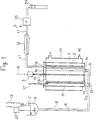
- Fig. 1 is a view to explain an outline of the continuous polymerization apparatus of present invention.
- Fig. 2 is a view to explain another outline of the continuous polymerization apparatus of present invention.
- Fig. 3 is a view to explain the Taylor vortex.
- Fig. 4 is a view to explain the jacket for heating and cooling and the reaction vessel main body partly in section.
- Fig. 5 is a cross-sectional view of the inner cylinder.
- Fig. 6 is an enlarged side view of bottom plates of the main bodies 1 and 10.
- Fig. 7 is an enlarged top view of bottom plates of the main bodies 1 and 10.
- Fig. 8 is an enlarged view to explain the shaft bearing.
- Fig. 1 shows an outline of the continuous polymerization apparatus of this invention.
- This apparatus has the reaction vessel main body 1, inner cylinder 2, motor 3 which is a rotating means, supplying means 4, and means for taking out 5.
- the reaction vessel main body 1 has a cylinder shape inner face and its provisional center axis 6 is set in such a manner as to have a vertical direction.
- the inner cylinder 2 has a cylindrical stainless steel plate having an outer face to make a coaxial double cylinder with an inner face of the main body 1, and it shows a cylindrical shape by that the lower side face ( the bottom face ) and the upper side face ( the top face ) are, respectively, closed by the bottom plate 2a and the upper plate 2b which are both made by the same material and set by welding.
- the inner cylinder 2, bottom plate 2a, and upper plate 2b consists of the same material, for example, a stainless steel.
- the bottom plate 2a and upper plate 2b of the inner cylinder are firmly set by welding with the rotating axis 15, which rotates by the motor 3.
- the inner cylinder 2 is able to rotate freely by the motor 3 around the center axis 6.
- the bottom face of reaction vessel main body 1 is a circular shape so as to face the bottom plate 2a of inner cylinder.
- the bottom plate 1a is set on the circular bottom face of the main body 1, and the inlet 1c to supply the material solution for polymerization 9 is installed with the bottom plate 1a so as to front on the bottom plate 2a of the inner cylinder.
- the supplying means 4 consists of the tank 7 to prepare a material solution for polymerization as an emulsion and the pipe route 8 which comes from a bottom face of this tank 7 to the supplying inlet 1c.
- the bulb 18 is arranged to control an amount of the flow.
- the tank 7 is installed so that its bottom face is a position higher that that of the upper plate 1b of the main body 1.
- a monomer is properly supplied dropwise from the dropping funnel 13 and, the stirrer 21 is set to stir the material solution 9.
- the taking-out outlet 1d is set on the upper plate 1b which closes the cylindrical upper face of the main body 1.
- the means for taking-out 5 consists of the pipe route 11, which comes from the outlet 1d to the bath for storing a reaction solution 30, and the cooler 12 and rotary pump 13 which are installed on the way of pipe route 11.
- the jacket for heating and cooling 14 is set on the outside of main body 1. By running warm water 16 in the jacket 14 for heating and cooling, the polymerization temperature in the inside of main body 1 is properly controlled.
- the material solution for polymerization 9 prepared in the tank 7 as an emulsion or a suspension comes into the main body 1 from the supplying inlet 1c through the pipe route 8 by the pull of gravity. At this time, the material solution 9 does not directly enter into the clearance which is between the inner cylinder and the outer cylinder of the double cylinder, but it once hits on the bottom plate 2a of the inner cylinder, moves in such a manner as to spread sideways, and enters into the clearance. Thus, without disturbing Taylor vortices caused between the inner cylinder and the outer cylinder, the material solution can be continuously supplied.
- the polymerization is carried out in the clearance between the cylinders by Taylor vortices caused by rotating the inner cylinder 2 by the motor 3 ( refer to Figure 3 ).
- thermometer 9 is set in an inside of the main body 1, temperature control is easily carried out.
- the material solution 9 which was transferred upward is an emulsified or a suspended reaction solution and taken out by operating the rotary pump 13. If necessary, the solution 9 is cooled by the cooler 12 on the way of pipe route 11.
- the reaction solution taken out is stored in the bath for storing 30. Polymer particles are obtained by filtering this reaction solution.
- Fig. 2 shows another outline of the continuous polymerization apparatus of this invention.
- the material solution is supplied from an upper side of the double cylinder, that is from the supplying inlet 10c arranged on the upper plate 10b of reaction vessel main body 10, and the apparatus is similar to that shown in Fig. 1 except that taking-out of the reaction solution is carried out at a lower side of the double cylinder by the pull of gravity, that is from the taking-out outlet 10d set on the bottom plate 10a of reaction vessel main body 10.
- the preliminary heater 20 may be arranged so as to be capable of heating before the material solution is placed into the reaction vessel main body 10.
- both the supply and taking-out are carried out by the pull of gravity. Control of the flow amount can be carried out, for example, by the bulb 19 arranged at the pipe route on an lower side of the taking-out outlet 10d.
- reaction may be carried out by arranging several units of an apparatus of this type ( a reaction vessel ) in series and running the material solution in sequence and, thereby, dividing the reaction into a multistep.
- nucleus particles for carrying out the emulsion polymerization are produced as follows.
- a mixture solution was made by dissolving 0,02 g of a chain-transfer agent (carbon tetrabromide) in a mixture of 8 g of styrene, 4 g of n-butyl acrylate, and 8 g of ethylene glycol dimethacrylate.
- a chain-transfer agent carbon tetrabromide
- 30 g of an emulsifier an amphoteric surfactant, made by Nippon Paint Co., Ltd., trade name "R-4820 Varnish”
- R-4820 Varnish an amphoteric surfactant
- aqueous initiator solution a mixture of 10 g of deionized water, 0.2 of azobiscyanovaleric acid, and 0,128 g of dimethylethanolamine
- a thus-obtained mixture was allowed to react at 83 °C for 1 hour, whereby an emulsified solution of homogeneous crosslinked nucleus particles having a particle diameter of 22 nm (seed emulsion I) was obtained.
- Figs. 1 and 2 were used. Details of each apparatus are as follows ( refer to Figs. 4 to 8 ).
- a matter denoted by the same symbol and sign represents the same matter.
- the numeral value which represents a size in the figures has an unit of mm.
- Reaction vessel main body 1
- a glass pipe heat-resistant glass
- the supplying inlet was a penetrating hole having 15 mm in diameter arranged at a position 20 mm apart outward from a center of the bottom plate (which was, in an apparatus shown in Fig. 2, arranged on the upper plate ) ( refer to Figs. 6 and 7 ).
- the outlet for taking out is a penetrating hole having 15 mm in diameter arranged at a position 20 mm apart outward from a center of the upper plate (which was, in an apparatus shown in Fig. 2, arranged on the bottom plate ) ( refer to Figs. 6 and 7 ).
- the shaft bearing was arranged by putting an shaft bearing plate 31 of a doughnut shape into the penetrating hole 33 having a radius of 18 mm from the centers of the upper plate and the bottom plate, wherein the bearing plate 31 had an outer diameter of 18 mm and the penetrating hole 32 of 8 mm in inner diameter, was made by a tetrafluoroethylene resin, and also, had a thickness of 5 mm ( refer to Figs. 6 to 8 ).
- the inner cylinder 2 was made by incorporating; an upper plate consisting of a stainless plate of 2 mm in thickness and 52.9 mm in diameter and a bottom plate consisting of a stainless plate of 2 mm in thickness; a bottom plate consisting of a stainless plate of 2 mm in thickness and 52.9 mm in diameter; and a stainless pipe of 3.8 mm in thickness, 60.5 mm in outer diameter, and 400 mm in length; into one body by welding.
- the volume of a practically-used reaction bath ( a volume of the clearance between the double cylinders made by the main body 1 and the inner cylinder 2 ) was 1700 cm3.
- the rotating shaft 15 was made by welding a stainless rod of 645 mm in length and 8 mm in diameter with the upper and bottom plates of the inner cylinder 2 and it was supported by the upper and bottom plates of the main body 1 in such a manner as to be capable of freely rotating.
- the jacket for heating 14 was made by glass ( heat-resistant glass ) of 3 mm in thickness, 150 mm in outer diameter, and 345 mm in length, and it was installed in such a manner as to cover an area of 30 mm from both ends of the main body 1.
- a monomer a mixture of 72 g of styrene, 36 g of n-butyl acrylate, and 72 g of ethylene glycol dimethacrylate
- an aqueous initiator solution a mixture of 70.3 g of deionized water, 1.8 g of azobiscyanovaleric acid, and 1.2 g of dimethylethanolamine
- Polymer particles were obtained by carrying out the emulsion polymerization continuously under the conditions shown in Table 3 and by using a conventional reaction vessel of a multistage wing bath type.
- the material solutions had the same formulation to those in the examples 1 and 2 ( refer to Table 1 ).
- An outline of the apparatus is as follows. Volume: 645 ml Inner diameter: 50 mm Number of stage: 7 Height of one stage: 50 mm Wing for stirring: four flat-vaned turbine having a 32 mm diameter.
- Partition plate plate having an opening of 20 mm in diameter, of which center is the stirring shaft.
- Obstacle plate rectangular lumbers of 3 mm x 3 mm were installed at three positions along the wall. Supply: the lowest stage Taking-out: the top stage
- the average particle diameter was measured by a dynamic light-scattering measurement apparatus, made by Otsuka Electronics Co., Ltd. (trade name "LPA 3000, 3100") and a transmission electron microscope, made by Japan Electron Optics Laboratory Co., Ltd, (trade name "JEM-2000 FX II").
- the particle distribution was investigated by image processing of photographs by a transmission electron microscope.
- the conversion was determined by a nonvolatile portion converting method.
- the attaching amount of cohering products was determined by air-drying a residue on the 400 mesh sieve and calculating a difference by weight between this dried residue and the amount of a solid portion in the material solution ( in this case, a portion passed through the sieve was regarded as only a liquid ).
- the stirring condition was investigated by a naked eye observation of the movement of a reaction solution during the emulsion polymerization and shown by the following standard. gentle ⁇ almost no wave on the air-liquid interface. too strong ⁇ intensive waving on the air-liquid interface.
- the examples shows particle diameter distributions in the electron microscope photographs decreased by an amount of from 10 to 20 % and conversion improved by an amount of about 5 %.
- the examples 4 and 5 there is found an extremely reducing effect on the attaching amount of cohering products.
- the comparative examples shows decrease in the conversion, large particle diameter distributions, and because of a strong stirring force, there concentratedly generated cohering products on the feather surface around the material-supplying inlet. Besides, since temperature control was difficult by generating reaction heat in the comparative example 3, the supplying amount was forced to decrease.
- a suspending solution prepared by the same formulation and method to those used for the example 6 was continuously supplied at a flowing amount of 8.3 ml per minute by using a multistep wing bath type reaction vessel to carry out continuously the suspension polymerization at a reaction temperature of from 81 to 83°C with an average residence time of 180 minutes, and an obtained dispersed solution was filtered by a 200 mesh net to remove coarse particles and dried, whereby a crosslinked resin particle powder having an average particle diameter of 33 ⁇ m was obtained.
- the yield was 76 %.
Applications Claiming Priority (4)
| Application Number | Priority Date | Filing Date | Title |
|---|---|---|---|
| JP1458191 | 1991-02-05 | ||
| JP14581/91 | 1991-02-05 | ||
| JP274355/91 | 1991-10-22 | ||
| JP3274355A JPH04363303A (ja) | 1991-02-05 | 1991-10-22 | 連続重合方法および装置 |
Publications (2)
| Publication Number | Publication Date |
|---|---|
| EP0498583A1 true EP0498583A1 (fr) | 1992-08-12 |
| EP0498583B1 EP0498583B1 (fr) | 1996-10-09 |
Family
ID=26350546
Family Applications (1)
| Application Number | Title | Priority Date | Filing Date |
|---|---|---|---|
| EP92300870A Revoked EP0498583B1 (fr) | 1991-02-05 | 1992-01-31 | Méthode de polymérisation en continue et appareil |
Country Status (5)
| Country | Link |
|---|---|
| US (2) | US5340891A (fr) |
| EP (1) | EP0498583B1 (fr) |
| JP (1) | JPH04363303A (fr) |
| CA (1) | CA2060441A1 (fr) |
| DE (1) | DE69214312T2 (fr) |
Cited By (21)
| Publication number | Priority date | Publication date | Assignee | Title |
|---|---|---|---|---|
| WO1996027433A1 (fr) * | 1995-03-06 | 1996-09-12 | E.I. Du Pont De Nemours And Company | Appareil et procede de melange de liquides |
| WO1998022524A1 (fr) * | 1996-11-20 | 1998-05-28 | Basf Aktiengesellschaft | Procede de reticulation continue de produits de condensation et d'addition |
| DE19828742A1 (de) * | 1998-06-27 | 1999-12-30 | Basf Coatings Ag | Taylorreaktor für Stoffumwandlungen, bei deren Verlauf einer Änderung der Viskosität v des Reaktionsmediums eintritt |
| WO2002049756A1 (fr) * | 2000-12-21 | 2002-06-27 | Ciba Specialty Chemicals Water Treatments Limited | Reacteur tubulaire equipe de cylindres coaxiaux et procede d'utilisation dudit reacteur |
| WO2003029310A1 (fr) * | 2001-09-28 | 2003-04-10 | Röhm Gbmh & Co.Kg | Procede et dispositif de fabrication d'un poly(meth)acrylate de poids moleculaire eleve |
| US6727316B1 (en) | 1999-06-30 | 2004-04-27 | Basf Coatings Ag | Coating material and its use for producing filler coats and stone impact protection primers |
| US6737468B1 (en) | 1999-07-02 | 2004-05-18 | Basf Coatings Ag | Base coat and its use for producing color and/or effect-producing base coatings and multi-layer coatings |
| US6797761B2 (en) | 2000-02-10 | 2004-09-28 | Basf Coatings Ag | Aqueous primary dispersions, method for preparation and use thereof |
| US6815081B1 (en) | 1999-06-30 | 2004-11-09 | Basf Coatings Ag | Coloring and/or effect-creating multilayer enamel coating, method for the production thereof and its use |
| US6822038B1 (en) | 1999-07-12 | 2004-11-23 | Basf Coatings Ac | Aqueous coating substance, method for its production and its use |
| US6822044B1 (en) | 1999-07-02 | 2004-11-23 | Basf Coatings Ag | Varnish and its use for producing varnish coatings and color-and/or effect-producing multi-layer coatings |
| US6884839B1 (en) | 1999-12-11 | 2005-04-26 | Basf Coatings Ag | Aqueous primary dispersions and coating matters, a method for producing same and the use thereof |
| WO2005047401A2 (fr) | 2003-11-17 | 2005-05-26 | Basf Coatings Ag | Dispersions aqueuses a viscosite intrinseque, leur procede de production, et leur utilisation |
| US6946512B2 (en) | 2000-04-12 | 2005-09-20 | Basf Coatings Ag | Molding materials and method for producing molded parts |
| US7034074B2 (en) | 2000-04-14 | 2006-04-25 | Basf Coatings Ag | Aqueous primary dispersions and coating agents, methods for producing them and their use |
| US7157526B2 (en) | 2001-02-13 | 2007-01-02 | Basf Coatings Ag | Aqueous primary dispersion, substantially or completely devoid of volatile organic substances, method for the production thereof and use of the same |
| EP1897894A1 (fr) | 2001-06-01 | 2008-03-12 | BASF Coatings AG | Suspensions de laque pulvérulente (pâtes pulvérulentes) et laque pulvérulente, leur procédé de fabrication et leur utilisation |
| WO2008135211A1 (fr) * | 2007-05-04 | 2008-11-13 | Basf Coatings Ag | Procédé de polymérisation en continu pour la production de polymères à étroite distribution de masse molaire, et réacteur taylor-couette pour la mise en oeuvre de ce procédé |
| US7479520B2 (en) | 2001-02-13 | 2009-01-20 | Basf Coatings Ag | Aqueous coating substance that is substantially or completely free of volatile organic substances, method for producing the same and the use thereof |
| US7855266B2 (en) | 1999-11-05 | 2010-12-21 | Basf Coatings Ag | Method for multilayer coatings with self-crosslinking graft polyurethane copolymers, self-crosslinking polyurethanes and graft copolymers thereof |
| WO2018001474A1 (fr) | 2016-06-29 | 2018-01-04 | Wacker Chemie Ag | Procédés de fabrication de copolymères d'acétate de vinyle et d'éthylène par polymérisation en émulsion |
Families Citing this family (22)
| Publication number | Priority date | Publication date | Assignee | Title |
|---|---|---|---|---|
| CA2088129A1 (fr) * | 1992-02-06 | 1993-08-07 | Fritz Erdmann Kempter | Polymerisation continue de monomeres vinyliques |
| CA2127140A1 (fr) * | 1993-07-19 | 1995-01-20 | James E. Cantrill | Particulation d'un sirop metastable |
| US5551859A (en) * | 1993-07-19 | 1996-09-03 | Novacor Chemicals (International) S.A. | Particulator |
| CA2127141A1 (fr) * | 1993-07-19 | 1995-01-20 | James E. Cantrill | Determination de la taille de particules |
| US5861129A (en) * | 1995-09-13 | 1999-01-19 | Katoot; Mohammad W. | Polymer optical fibers and process for manufacture thereof |
| US6200503B1 (en) | 1996-09-13 | 2001-03-13 | Mohammad W. Katoot | Graded index polymer optical fibers and process for manufacture thereof |
| US6091872A (en) * | 1996-10-29 | 2000-07-18 | Katoot; Mohammad W. | Optical fiber imaging system |
| US6365072B1 (en) | 1999-03-19 | 2002-04-02 | Mk Industries, Inc. | Polymer optical fibers and process for manufacturing thereof |
| FR2796966B1 (fr) | 1999-07-30 | 2001-09-21 | Ugine Sa | Procede de fabrication de bandes minces en acier de type "trip" et bandes minces ainsi obtenues |
| DE19960389B4 (de) * | 1999-12-15 | 2009-01-15 | Basf Coatings Ag | Verfahren zur Polymerisation olefinisch ungesättigter Monomere mittels eines Taylorreaktors |
| DE10149015B4 (de) * | 2001-10-04 | 2005-04-14 | Basf Coatings Ag | Verfahren zur kontinuierlichen Polymerisation in Masse und Taylorreaktor für seine Durchführung |
| US20050284618A1 (en) * | 2004-06-29 | 2005-12-29 | Mcgrevy Alan N | Counter current temperature control configuration |
| US20050287670A1 (en) * | 2004-06-29 | 2005-12-29 | Gulliver Eric A | Cell culturing systems, methods and apparatus |
| WO2007036157A1 (fr) * | 2005-09-30 | 2007-04-05 | Accelergy Shanghai R & D Center Co., Ltd | Appareil de mélange et de réaction |
| JP5000613B2 (ja) * | 2008-09-30 | 2012-08-15 | 株式会社日本触媒 | 有機粒子含有組成物 |
| EP3305816A4 (fr) | 2015-06-04 | 2019-02-27 | Nippon Shokubai Co., Ltd. | Particules fines de polymère organique |
| KR102635153B1 (ko) * | 2018-09-27 | 2024-02-13 | 가부시키가이샤 닛폰 쇼쿠바이 | 흡수성 수지의 제조 방법 및 흡수성 수지 |
| KR102116444B1 (ko) * | 2019-10-04 | 2020-05-28 | 한국화학연구원 | 구형 비드의 제조방법 |
| CN111151211A (zh) * | 2020-01-20 | 2020-05-15 | 南通海晴医药科技有限公司 | 一种反应器及其使用方法 |
| CH717232A1 (de) * | 2020-03-16 | 2021-09-30 | Shcheblanov Aleksandr | Generator zum Erzeugen rigförmiger und räumlicher Wirbel in einer Flüssigkeit. |
| CN111790331A (zh) * | 2020-07-29 | 2020-10-20 | 贵州微化科技有限公司 | 一种相对运动的环隙微反应器 |
| CN116237095A (zh) * | 2023-02-18 | 2023-06-09 | 四川大学 | 基于浸润原理可控制备单分散乳液的微流控方法 |
Citations (3)
| Publication number | Priority date | Publication date | Assignee | Title |
|---|---|---|---|---|
| NL65551C (fr) * | ||||
| FR923042A (fr) * | 1946-03-01 | 1947-06-25 | Shell Dev | Procédé d'établissement du contact entre les fluides |
| DD230157A3 (de) * | 1982-03-04 | 1985-11-27 | Giprokaucuk | Reaktor zur durchfuehrung eines polymerisationsprozesses |
Family Cites Families (2)
| Publication number | Priority date | Publication date | Assignee | Title |
|---|---|---|---|---|
| DE230157C (fr) * | ||||
| US3424733A (en) * | 1963-04-16 | 1969-01-28 | Phillips Petroleum Co | Method and apparatus for handling of a fluid |
-
1991
- 1991-10-22 JP JP3274355A patent/JPH04363303A/ja active Pending
-
1992
- 1992-01-31 DE DE69214312T patent/DE69214312T2/de not_active Revoked
- 1992-01-31 CA CA002060441A patent/CA2060441A1/fr not_active Abandoned
- 1992-01-31 EP EP92300870A patent/EP0498583B1/fr not_active Revoked
-
1993
- 1993-11-29 US US08/158,924 patent/US5340891A/en not_active Expired - Fee Related
-
1994
- 1994-03-30 US US08/221,392 patent/US5470539A/en not_active Expired - Fee Related
Patent Citations (3)
| Publication number | Priority date | Publication date | Assignee | Title |
|---|---|---|---|---|
| NL65551C (fr) * | ||||
| FR923042A (fr) * | 1946-03-01 | 1947-06-25 | Shell Dev | Procédé d'établissement du contact entre les fluides |
| DD230157A3 (de) * | 1982-03-04 | 1985-11-27 | Giprokaucuk | Reaktor zur durchfuehrung eines polymerisationsprozesses |
Cited By (26)
| Publication number | Priority date | Publication date | Assignee | Title |
|---|---|---|---|---|
| WO1996027433A1 (fr) * | 1995-03-06 | 1996-09-12 | E.I. Du Pont De Nemours And Company | Appareil et procede de melange de liquides |
| WO1998022524A1 (fr) * | 1996-11-20 | 1998-05-28 | Basf Aktiengesellschaft | Procede de reticulation continue de produits de condensation et d'addition |
| DE19828742A1 (de) * | 1998-06-27 | 1999-12-30 | Basf Coatings Ag | Taylorreaktor für Stoffumwandlungen, bei deren Verlauf einer Änderung der Viskosität v des Reaktionsmediums eintritt |
| WO2000000280A1 (fr) * | 1998-06-27 | 2000-01-06 | Basf Coatings Ag | REACTEUR DE TAYLOR POUR TRANSFORMATIONS DE MATIERES ACCOMPAGNEES D'UNE MODIFICATION DE LA VISCOSITE ξ DU MILIEU DE REACTION |
| US7122161B1 (en) | 1998-06-27 | 2006-10-17 | Basf Coatings Ag | Taylor reactor for materials conversion in the course of which a change in viscosity of the reaction medium occurs |
| US6727316B1 (en) | 1999-06-30 | 2004-04-27 | Basf Coatings Ag | Coating material and its use for producing filler coats and stone impact protection primers |
| US6815081B1 (en) | 1999-06-30 | 2004-11-09 | Basf Coatings Ag | Coloring and/or effect-creating multilayer enamel coating, method for the production thereof and its use |
| US6822044B1 (en) | 1999-07-02 | 2004-11-23 | Basf Coatings Ag | Varnish and its use for producing varnish coatings and color-and/or effect-producing multi-layer coatings |
| US6737468B1 (en) | 1999-07-02 | 2004-05-18 | Basf Coatings Ag | Base coat and its use for producing color and/or effect-producing base coatings and multi-layer coatings |
| US6822038B1 (en) | 1999-07-12 | 2004-11-23 | Basf Coatings Ac | Aqueous coating substance, method for its production and its use |
| US7855266B2 (en) | 1999-11-05 | 2010-12-21 | Basf Coatings Ag | Method for multilayer coatings with self-crosslinking graft polyurethane copolymers, self-crosslinking polyurethanes and graft copolymers thereof |
| US6884839B1 (en) | 1999-12-11 | 2005-04-26 | Basf Coatings Ag | Aqueous primary dispersions and coating matters, a method for producing same and the use thereof |
| US6797761B2 (en) | 2000-02-10 | 2004-09-28 | Basf Coatings Ag | Aqueous primary dispersions, method for preparation and use thereof |
| US6946512B2 (en) | 2000-04-12 | 2005-09-20 | Basf Coatings Ag | Molding materials and method for producing molded parts |
| US7034074B2 (en) | 2000-04-14 | 2006-04-25 | Basf Coatings Ag | Aqueous primary dispersions and coating agents, methods for producing them and their use |
| CN100346871C (zh) * | 2000-12-21 | 2007-11-07 | 西巴特殊化学水处理有限公司 | 带有同轴圆筒的管式反应器及其使用方法 |
| US7601786B2 (en) | 2000-12-21 | 2009-10-13 | Ciba Specialty Chemicals Water Treatments Ltd. | Tubular reactor with coaxial cylinders and process using this reactor |
| WO2002049756A1 (fr) * | 2000-12-21 | 2002-06-27 | Ciba Specialty Chemicals Water Treatments Limited | Reacteur tubulaire equipe de cylindres coaxiaux et procede d'utilisation dudit reacteur |
| US7157526B2 (en) | 2001-02-13 | 2007-01-02 | Basf Coatings Ag | Aqueous primary dispersion, substantially or completely devoid of volatile organic substances, method for the production thereof and use of the same |
| US7479520B2 (en) | 2001-02-13 | 2009-01-20 | Basf Coatings Ag | Aqueous coating substance that is substantially or completely free of volatile organic substances, method for producing the same and the use thereof |
| EP1897894A1 (fr) | 2001-06-01 | 2008-03-12 | BASF Coatings AG | Suspensions de laque pulvérulente (pâtes pulvérulentes) et laque pulvérulente, leur procédé de fabrication et leur utilisation |
| WO2003029310A1 (fr) * | 2001-09-28 | 2003-04-10 | Röhm Gbmh & Co.Kg | Procede et dispositif de fabrication d'un poly(meth)acrylate de poids moleculaire eleve |
| WO2005047401A2 (fr) | 2003-11-17 | 2005-05-26 | Basf Coatings Ag | Dispersions aqueuses a viscosite intrinseque, leur procede de production, et leur utilisation |
| WO2008135211A1 (fr) * | 2007-05-04 | 2008-11-13 | Basf Coatings Ag | Procédé de polymérisation en continu pour la production de polymères à étroite distribution de masse molaire, et réacteur taylor-couette pour la mise en oeuvre de ce procédé |
| WO2018001474A1 (fr) | 2016-06-29 | 2018-01-04 | Wacker Chemie Ag | Procédés de fabrication de copolymères d'acétate de vinyle et d'éthylène par polymérisation en émulsion |
| US10519255B2 (en) | 2016-06-29 | 2019-12-31 | Wacker Chemie Ag | Process for preparing vinyl acetate-ethylene copolymers by emulsion polymerization |
Also Published As
| Publication number | Publication date |
|---|---|
| DE69214312T2 (de) | 1997-05-07 |
| CA2060441A1 (fr) | 1992-08-06 |
| DE69214312D1 (de) | 1996-11-14 |
| US5340891A (en) | 1994-08-23 |
| JPH04363303A (ja) | 1992-12-16 |
| US5470539A (en) | 1995-11-28 |
| EP0498583B1 (fr) | 1996-10-09 |
Similar Documents
| Publication | Publication Date | Title |
|---|---|---|
| US5340891A (en) | Continuous polymerization method and apparatus | |
| EP0173518B1 (fr) | Procédé de préparation de particules de polymères de grandeur uniforme | |
| Paquet Jr et al. | Tubular reactors for emulsion polymerization: I. Experimental investigation | |
| EP0443609B1 (fr) | Méthode et appareil de polymérisation en suspension | |
| EP1591158B1 (fr) | Contrôle du cisaillement et de la turbulence de la configuration d'écoulement dans une phase liquide dans un récipient | |
| JPH10195205A (ja) | 樹脂粒子の製造方法、製造装置およびその製品 | |
| JPH08109208A (ja) | 乳化重合用シード粒子製造方法及び連続多段乳化重合方法 | |
| JPH05132504A (ja) | 重合体粒子の製造方法 | |
| US3003986A (en) | Process of emulsion polymerization of ethylenically unsaturated monomers utilizing taylor ring flow pattern | |
| US5608017A (en) | Suspension polymerization method | |
| US3950138A (en) | Apparatus for conducting chemical reactions, particularly polymerization, continuously | |
| JP2001522394A (ja) | ミクロ懸濁液から管状反応器において粒子状単独重合体及び共重合体を製造する方法 | |
| JPH04150934A (ja) | エマルジョン樹脂の製造方法 | |
| US5717041A (en) | Suspension polymerization method and particles obtained therewith | |
| JPH06102684B2 (ja) | 懸濁重合法 | |
| JP3380131B2 (ja) | 重合体粒子の製造方法 | |
| JP2832867B2 (ja) | 懸濁重合法 | |
| JP2005179427A (ja) | メタクリル樹脂粒子の製造方法 | |
| JP3328033B2 (ja) | 懸濁重合方法 | |
| JPH03131603A (ja) | 懸濁重合法 | |
| Zhang | A study of suspension polymerisation of Methyl Mathacrylate and Styrene in a batch oscillatory baffled reactor | |
| JP4817358B2 (ja) | ビニル系樹脂微粒子の製造方法 | |
| JPS6286001A (ja) | ポリマー粒子分散液の製造方法 | |
| JPH044202A (ja) | 懸濁重合法 | |
| JPH0632806A (ja) | 連続重合装置 |
Legal Events
| Date | Code | Title | Description |
|---|---|---|---|
| PUAI | Public reference made under article 153(3) epc to a published international application that has entered the european phase |
Free format text: ORIGINAL CODE: 0009012 |
|
| AK | Designated contracting states |
Kind code of ref document: A1 Designated state(s): DE FR GB NL |
|
| 17P | Request for examination filed |
Effective date: 19920918 |
|
| 17Q | First examination report despatched |
Effective date: 19930903 |
|
| GRAG | Despatch of communication of intention to grant |
Free format text: ORIGINAL CODE: EPIDOS AGRA |
|
| GRAH | Despatch of communication of intention to grant a patent |
Free format text: ORIGINAL CODE: EPIDOS IGRA |
|
| GRAH | Despatch of communication of intention to grant a patent |
Free format text: ORIGINAL CODE: EPIDOS IGRA |
|
| GRAA | (expected) grant |
Free format text: ORIGINAL CODE: 0009210 |
|
| AK | Designated contracting states |
Kind code of ref document: B1 Designated state(s): DE FR GB NL |
|
| PG25 | Lapsed in a contracting state [announced via postgrant information from national office to epo] |
Ref country code: NL Free format text: LAPSE BECAUSE OF FAILURE TO SUBMIT A TRANSLATION OF THE DESCRIPTION OR TO PAY THE FEE WITHIN THE PRESCRIBED TIME-LIMIT Effective date: 19961009 |
|
| ET | Fr: translation filed | ||
| REF | Corresponds to: |
Ref document number: 69214312 Country of ref document: DE Date of ref document: 19961114 |
|
| NLV1 | Nl: lapsed or annulled due to failure to fulfill the requirements of art. 29p and 29m of the patents act | ||
| PLBQ | Unpublished change to opponent data |
Free format text: ORIGINAL CODE: EPIDOS OPPO |
|
| PLBI | Opposition filed |
Free format text: ORIGINAL CODE: 0009260 |
|
| PLBF | Reply of patent proprietor to notice(s) of opposition |
Free format text: ORIGINAL CODE: EPIDOS OBSO |
|
| 26 | Opposition filed |
Opponent name: BASF AKTIENGESELLSCHAFT, LUDWIGSHAFEN Effective date: 19970703 |
|
| PLBF | Reply of patent proprietor to notice(s) of opposition |
Free format text: ORIGINAL CODE: EPIDOS OBSO |
|
| PGFP | Annual fee paid to national office [announced via postgrant information from national office to epo] |
Ref country code: FR Payment date: 19980109 Year of fee payment: 7 |
|
| PGFP | Annual fee paid to national office [announced via postgrant information from national office to epo] |
Ref country code: GB Payment date: 19980122 Year of fee payment: 7 |
|
| PGFP | Annual fee paid to national office [announced via postgrant information from national office to epo] |
Ref country code: DE Payment date: 19980206 Year of fee payment: 7 |
|
| RDAH | Patent revoked |
Free format text: ORIGINAL CODE: EPIDOS REVO |
|
| RDAG | Patent revoked |
Free format text: ORIGINAL CODE: 0009271 |
|
| STAA | Information on the status of an ep patent application or granted ep patent |
Free format text: STATUS: PATENT REVOKED |
|
| 27W | Patent revoked |
Effective date: 19990321 |
|
| GBPR | Gb: patent revoked under art. 102 of the ep convention designating the uk as contracting state |
Free format text: 990321 |