EP0494479B1 - Auf Glas basierende optische Platte und deren Herstellungsverfahren - Google Patents
Auf Glas basierende optische Platte und deren Herstellungsverfahren Download PDFInfo
- Publication number
- EP0494479B1 EP0494479B1 EP91300096A EP91300096A EP0494479B1 EP 0494479 B1 EP0494479 B1 EP 0494479B1 EP 91300096 A EP91300096 A EP 91300096A EP 91300096 A EP91300096 A EP 91300096A EP 0494479 B1 EP0494479 B1 EP 0494479B1
- Authority
- EP
- European Patent Office
- Prior art keywords
- laminate
- reflective
- optically
- glass
- forming
- Prior art date
- Legal status (The legal status is an assumption and is not a legal conclusion. Google has not performed a legal analysis and makes no representation as to the accuracy of the status listed.)
- Expired - Lifetime
Links
- 230000003287 optical effect Effects 0.000 title claims description 38
- 239000011521 glass Substances 0.000 title claims description 18
- 238000004519 manufacturing process Methods 0.000 title claims description 16
- 238000000034 method Methods 0.000 claims description 36
- 238000010030 laminating Methods 0.000 claims description 23
- 239000004411 aluminium Substances 0.000 claims description 19
- 229910052782 aluminium Inorganic materials 0.000 claims description 19
- BOTDANWDWHJENH-UHFFFAOYSA-N Tetraethyl orthosilicate Chemical compound CCO[Si](OCC)(OCC)OCC BOTDANWDWHJENH-UHFFFAOYSA-N 0.000 claims description 18
- XAGFODPZIPBFFR-UHFFFAOYSA-N aluminium Chemical compound [Al] XAGFODPZIPBFFR-UHFFFAOYSA-N 0.000 claims description 17
- 229910052751 metal Inorganic materials 0.000 claims description 16
- 239000002184 metal Substances 0.000 claims description 16
- MCULRUJILOGHCJ-UHFFFAOYSA-N triisobutylaluminium Chemical compound CC(C)C[Al](CC(C)C)CC(C)C MCULRUJILOGHCJ-UHFFFAOYSA-N 0.000 claims description 15
- 239000005340 laminated glass Substances 0.000 claims description 14
- 239000012530 fluid Substances 0.000 claims description 13
- 229920000642 polymer Polymers 0.000 claims description 13
- 239000000853 adhesive Substances 0.000 claims description 11
- 230000001070 adhesive effect Effects 0.000 claims description 11
- 238000004049 embossing Methods 0.000 claims description 10
- VYPSYNLAJGMNEJ-UHFFFAOYSA-N Silicium dioxide Chemical compound O=[Si]=O VYPSYNLAJGMNEJ-UHFFFAOYSA-N 0.000 claims description 8
- 150000001875 compounds Chemical class 0.000 claims description 7
- 230000000670 limiting effect Effects 0.000 claims description 7
- -1 silicate compound Chemical class 0.000 claims description 6
- 239000000654 additive Substances 0.000 claims description 5
- 239000007924 injection Substances 0.000 claims description 5
- 239000007787 solid Substances 0.000 claims description 5
- 238000002347 injection Methods 0.000 claims description 4
- 229920003229 poly(methyl methacrylate) Polymers 0.000 claims description 4
- 239000004926 polymethyl methacrylate Substances 0.000 claims description 4
- 235000012239 silicon dioxide Nutrition 0.000 claims description 4
- 239000000377 silicon dioxide Substances 0.000 claims description 4
- 238000007789 sealing Methods 0.000 claims description 3
- 229920000515 polycarbonate Polymers 0.000 claims description 2
- 239000004417 polycarbonate Substances 0.000 claims description 2
- 150000002902 organometallic compounds Chemical class 0.000 claims 4
- 238000005507 spraying Methods 0.000 claims 3
- QVGXLLKOCUKJST-UHFFFAOYSA-N atomic oxygen Chemical compound [O] QVGXLLKOCUKJST-UHFFFAOYSA-N 0.000 claims 1
- 229910052681 coesite Inorganic materials 0.000 claims 1
- 229910052906 cristobalite Inorganic materials 0.000 claims 1
- 229910052760 oxygen Inorganic materials 0.000 claims 1
- 239000001301 oxygen Substances 0.000 claims 1
- 229910052710 silicon Inorganic materials 0.000 claims 1
- 239000010703 silicon Substances 0.000 claims 1
- 229910052682 stishovite Inorganic materials 0.000 claims 1
- 229910052905 tridymite Inorganic materials 0.000 claims 1
- 239000010410 layer Substances 0.000 description 30
- 210000004907 gland Anatomy 0.000 description 16
- ATJFFYVFTNAWJD-UHFFFAOYSA-N Tin Chemical compound [Sn] ATJFFYVFTNAWJD-UHFFFAOYSA-N 0.000 description 15
- 239000007789 gas Substances 0.000 description 12
- 238000003475 lamination Methods 0.000 description 12
- XKRFYHLGVUSROY-UHFFFAOYSA-N Argon Chemical compound [Ar] XKRFYHLGVUSROY-UHFFFAOYSA-N 0.000 description 8
- 230000015572 biosynthetic process Effects 0.000 description 7
- 239000000975 dye Substances 0.000 description 6
- 229910052786 argon Inorganic materials 0.000 description 4
- 239000011261 inert gas Substances 0.000 description 4
- 230000001105 regulatory effect Effects 0.000 description 4
- 239000000758 substrate Substances 0.000 description 4
- LFQSCWFLJHTTHZ-UHFFFAOYSA-N Ethanol Chemical compound CCO LFQSCWFLJHTTHZ-UHFFFAOYSA-N 0.000 description 3
- OKKJLVBELUTLKV-UHFFFAOYSA-N Methanol Chemical compound OC OKKJLVBELUTLKV-UHFFFAOYSA-N 0.000 description 3
- 239000012790 adhesive layer Substances 0.000 description 3
- 150000004703 alkoxides Chemical class 0.000 description 3
- 238000005520 cutting process Methods 0.000 description 3
- 238000000151 deposition Methods 0.000 description 3
- 230000008021 deposition Effects 0.000 description 3
- 230000009977 dual effect Effects 0.000 description 3
- 238000000605 extraction Methods 0.000 description 3
- 230000002401 inhibitory effect Effects 0.000 description 3
- 230000036961 partial effect Effects 0.000 description 3
- 238000000197 pyrolysis Methods 0.000 description 3
- 125000004066 1-hydroxyethyl group Chemical group [H]OC([H])([*])C([H])([H])[H] 0.000 description 2
- IJGRMHOSHXDMSA-UHFFFAOYSA-N Atomic nitrogen Chemical compound N#N IJGRMHOSHXDMSA-UHFFFAOYSA-N 0.000 description 2
- LRHPLDYGYMQRHN-UHFFFAOYSA-N N-Butanol Chemical compound CCCCO LRHPLDYGYMQRHN-UHFFFAOYSA-N 0.000 description 2
- BPQQTUXANYXVAA-UHFFFAOYSA-N Orthosilicate Chemical compound [O-][Si]([O-])([O-])[O-] BPQQTUXANYXVAA-UHFFFAOYSA-N 0.000 description 2
- WQDUMFSSJAZKTM-UHFFFAOYSA-N Sodium methoxide Chemical compound [Na+].[O-]C WQDUMFSSJAZKTM-UHFFFAOYSA-N 0.000 description 2
- 238000000576 coating method Methods 0.000 description 2
- 239000002131 composite material Substances 0.000 description 2
- 239000000428 dust Substances 0.000 description 2
- 235000019441 ethanol Nutrition 0.000 description 2
- 239000007788 liquid Substances 0.000 description 2
- 230000007246 mechanism Effects 0.000 description 2
- 230000005499 meniscus Effects 0.000 description 2
- 239000000203 mixture Substances 0.000 description 2
- 238000005192 partition Methods 0.000 description 2
- 239000011253 protective coating Substances 0.000 description 2
- 230000005855 radiation Effects 0.000 description 2
- 239000005368 silicate glass Substances 0.000 description 2
- 239000000243 solution Substances 0.000 description 2
- 239000007921 spray Substances 0.000 description 2
- 238000003860 storage Methods 0.000 description 2
- 239000000126 substance Substances 0.000 description 2
- JLZIIHMTTRXXIN-UHFFFAOYSA-N 2-(2-hydroxy-4-methoxybenzoyl)benzoic acid Chemical compound OC1=CC(OC)=CC=C1C(=O)C1=CC=CC=C1C(O)=O JLZIIHMTTRXXIN-UHFFFAOYSA-N 0.000 description 1
- ZCILGMFPJBRCNO-UHFFFAOYSA-N 4-phenyl-2H-benzotriazol-5-ol Chemical class OC1=CC=C2NN=NC2=C1C1=CC=CC=C1 ZCILGMFPJBRCNO-UHFFFAOYSA-N 0.000 description 1
- 239000004215 Carbon black (E152) Substances 0.000 description 1
- XZMCDFZZKTWFGF-UHFFFAOYSA-N Cyanamide Chemical compound NC#N XZMCDFZZKTWFGF-UHFFFAOYSA-N 0.000 description 1
- 239000011358 absorbing material Substances 0.000 description 1
- 230000000996 additive effect Effects 0.000 description 1
- 239000000956 alloy Substances 0.000 description 1
- SMZOGRDCAXLAAR-UHFFFAOYSA-N aluminium isopropoxide Chemical compound [Al+3].CC(C)[O-].CC(C)[O-].CC(C)[O-] SMZOGRDCAXLAAR-UHFFFAOYSA-N 0.000 description 1
- 239000011230 binding agent Substances 0.000 description 1
- 230000000903 blocking effect Effects 0.000 description 1
- 239000001273 butane Substances 0.000 description 1
- 239000011575 calcium Substances 0.000 description 1
- AMJQWGIYCROUQF-UHFFFAOYSA-N calcium;methanolate Chemical compound [Ca+2].[O-]C.[O-]C AMJQWGIYCROUQF-UHFFFAOYSA-N 0.000 description 1
- 230000006835 compression Effects 0.000 description 1
- 238000007906 compression Methods 0.000 description 1
- 238000000748 compression moulding Methods 0.000 description 1
- 238000010924 continuous production Methods 0.000 description 1
- 238000000354 decomposition reaction Methods 0.000 description 1
- 230000007547 defect Effects 0.000 description 1
- 238000005137 deposition process Methods 0.000 description 1
- SRXOCFMDUSFFAK-UHFFFAOYSA-N dimethyl peroxide Chemical compound COOC SRXOCFMDUSFFAK-UHFFFAOYSA-N 0.000 description 1
- 230000003467 diminishing effect Effects 0.000 description 1
- 229910001873 dinitrogen Inorganic materials 0.000 description 1
- 238000007598 dipping method Methods 0.000 description 1
- 230000000694 effects Effects 0.000 description 1
- 238000005516 engineering process Methods 0.000 description 1
- 239000000284 extract Substances 0.000 description 1
- 229930195733 hydrocarbon Natural products 0.000 description 1
- 150000002430 hydrocarbons Chemical class 0.000 description 1
- 239000001257 hydrogen Substances 0.000 description 1
- 229910052739 hydrogen Inorganic materials 0.000 description 1
- 125000004435 hydrogen atom Chemical class [H]* 0.000 description 1
- 230000000977 initiatory effect Effects 0.000 description 1
- 238000001746 injection moulding Methods 0.000 description 1
- 229910052909 inorganic silicate Inorganic materials 0.000 description 1
- 229910000765 intermetallic Inorganic materials 0.000 description 1
- AZVCGYPLLBEUNV-UHFFFAOYSA-N lithium;ethanolate Chemical compound [Li+].CC[O-] AZVCGYPLLBEUNV-UHFFFAOYSA-N 0.000 description 1
- 239000000463 material Substances 0.000 description 1
- 229910001092 metal group alloy Inorganic materials 0.000 description 1
- GRVDJDISBSALJP-UHFFFAOYSA-N methyloxidanyl Chemical compound [O]C GRVDJDISBSALJP-UHFFFAOYSA-N 0.000 description 1
- 238000000465 moulding Methods 0.000 description 1
- IJDNQMDRQITEOD-UHFFFAOYSA-N n-butane Chemical compound CCCC IJDNQMDRQITEOD-UHFFFAOYSA-N 0.000 description 1
- OFBQJSOFQDEBGM-UHFFFAOYSA-N n-pentane Natural products CCCCC OFBQJSOFQDEBGM-UHFFFAOYSA-N 0.000 description 1
- 239000003960 organic solvent Substances 0.000 description 1
- 239000002245 particle Substances 0.000 description 1
- 238000007747 plating Methods 0.000 description 1
- 229920002959 polymer blend Polymers 0.000 description 1
- 229920002635 polyurethane Polymers 0.000 description 1
- 239000004814 polyurethane Substances 0.000 description 1
- 238000001556 precipitation Methods 0.000 description 1
- BDERNNFJNOPAEC-UHFFFAOYSA-N propan-1-ol Chemical compound CCCO BDERNNFJNOPAEC-UHFFFAOYSA-N 0.000 description 1
- 230000001681 protective effect Effects 0.000 description 1
- 239000011241 protective layer Substances 0.000 description 1
- 239000000985 reactive dye Substances 0.000 description 1
- 238000002310 reflectometry Methods 0.000 description 1
- 239000011347 resin Substances 0.000 description 1
- 229920005989 resin Polymers 0.000 description 1
- 230000000717 retained effect Effects 0.000 description 1
- 238000005096 rolling process Methods 0.000 description 1
- 238000000926 separation method Methods 0.000 description 1
- 239000011734 sodium Substances 0.000 description 1
- 239000002904 solvent Substances 0.000 description 1
- 238000004528 spin coating Methods 0.000 description 1
- 238000004544 sputter deposition Methods 0.000 description 1
- 239000002344 surface layer Substances 0.000 description 1
- 229920001169 thermoplastic Polymers 0.000 description 1
- 229920001187 thermosetting polymer Polymers 0.000 description 1
- 239000004416 thermosoftening plastic Substances 0.000 description 1
- 238000002834 transmittance Methods 0.000 description 1
- 238000009966 trimming Methods 0.000 description 1
- 238000001771 vacuum deposition Methods 0.000 description 1
Images

Classifications
-
- G—PHYSICS
- G11—INFORMATION STORAGE
- G11B—INFORMATION STORAGE BASED ON RELATIVE MOVEMENT BETWEEN RECORD CARRIER AND TRANSDUCER
- G11B7/00—Recording or reproducing by optical means, e.g. recording using a thermal beam of optical radiation by modifying optical properties or the physical structure, reproducing using an optical beam at lower power by sensing optical properties; Record carriers therefor
- G11B7/24—Record carriers characterised by shape, structure or physical properties, or by the selection of the material
- G11B7/26—Apparatus or processes specially adapted for the manufacture of record carriers
-
- C—CHEMISTRY; METALLURGY
- C03—GLASS; MINERAL OR SLAG WOOL
- C03B—MANUFACTURE, SHAPING, OR SUPPLEMENTARY PROCESSES
- C03B18/00—Shaping glass in contact with the surface of a liquid
- C03B18/02—Forming sheets
-
- C—CHEMISTRY; METALLURGY
- C03—GLASS; MINERAL OR SLAG WOOL
- C03B—MANUFACTURE, SHAPING, OR SUPPLEMENTARY PROCESSES
- C03B19/00—Other methods of shaping glass
- C03B19/14—Other methods of shaping glass by gas- or vapour- phase reaction processes
-
- C—CHEMISTRY; METALLURGY
- C03—GLASS; MINERAL OR SLAG WOOL
- C03C—CHEMICAL COMPOSITION OF GLASSES, GLAZES OR VITREOUS ENAMELS; SURFACE TREATMENT OF GLASS; SURFACE TREATMENT OF FIBRES OR FILAMENTS MADE FROM GLASS, MINERALS OR SLAGS; JOINING GLASS TO GLASS OR OTHER MATERIALS
- C03C17/00—Surface treatment of glass, not in the form of fibres or filaments, by coating
- C03C17/06—Surface treatment of glass, not in the form of fibres or filaments, by coating with metals
- C03C17/09—Surface treatment of glass, not in the form of fibres or filaments, by coating with metals by deposition from the vapour phase
-
- C—CHEMISTRY; METALLURGY
- C03—GLASS; MINERAL OR SLAG WOOL
- C03C—CHEMICAL COMPOSITION OF GLASSES, GLAZES OR VITREOUS ENAMELS; SURFACE TREATMENT OF GLASS; SURFACE TREATMENT OF FIBRES OR FILAMENTS MADE FROM GLASS, MINERALS OR SLAGS; JOINING GLASS TO GLASS OR OTHER MATERIALS
- C03C2217/00—Coatings on glass
- C03C2217/20—Materials for coating a single layer on glass
- C03C2217/25—Metals
- C03C2217/251—Al, Cu, Mg or noble metals
- C03C2217/252—Al
-
- C—CHEMISTRY; METALLURGY
- C03—GLASS; MINERAL OR SLAG WOOL
- C03C—CHEMICAL COMPOSITION OF GLASSES, GLAZES OR VITREOUS ENAMELS; SURFACE TREATMENT OF GLASS; SURFACE TREATMENT OF FIBRES OR FILAMENTS MADE FROM GLASS, MINERALS OR SLAGS; JOINING GLASS TO GLASS OR OTHER MATERIALS
- C03C2218/00—Methods for coating glass
- C03C2218/10—Deposition methods
- C03C2218/15—Deposition methods from the vapour phase
- C03C2218/152—Deposition methods from the vapour phase by cvd
-
- Y—GENERAL TAGGING OF NEW TECHNOLOGICAL DEVELOPMENTS; GENERAL TAGGING OF CROSS-SECTIONAL TECHNOLOGIES SPANNING OVER SEVERAL SECTIONS OF THE IPC; TECHNICAL SUBJECTS COVERED BY FORMER USPC CROSS-REFERENCE ART COLLECTIONS [XRACs] AND DIGESTS
- Y10—TECHNICAL SUBJECTS COVERED BY FORMER USPC
- Y10T—TECHNICAL SUBJECTS COVERED BY FORMER US CLASSIFICATION
- Y10T156/00—Adhesive bonding and miscellaneous chemical manufacture
- Y10T156/10—Methods of surface bonding and/or assembly therefor
- Y10T156/1002—Methods of surface bonding and/or assembly therefor with permanent bending or reshaping or surface deformation of self sustaining lamina
- Y10T156/1007—Running or continuous length work
- Y10T156/1023—Surface deformation only [e.g., embossing]
Definitions
- the invention relates to a method for the manufacture of a second surface optical recording storage disk, card or device with ultraviolet (UV) inhibiting characteristics
- Existing optical disk or card art relating to write once-read many (WORM), magneto-optical (erasable) type or similar optical recording devices generally consists of a laminated or multilayered structure having a rigid support substrate, a reflective layer, a photosensitive optically reactive second surface layer which is, depending upon disk or card application, covered by a first surface optically transparent protective coating layer.
- WORM write once-read many
- a photosensitive optically reactive second surface layer which is, depending upon disk or card application, covered by a first surface optically transparent protective coating layer.
- each said layer has been subsequently superimposed intermittently upon the preceding layer on a disk by disk basis, by various succeeding methods such as injection or compression molding, spin coating, sputtering, vacuum deposition, and, in general, by means of individual layer by layer lamination techniques.
- Each substrate is processed to receive succeeding such lamination coatings individually, serially or in batches of small numbers.
- first surface optically recordable laminations which have been conveniently and efficiently manufactured in relatively wide webs of great length and width.
- optical recording laminations can be manufactured in an efficient and economical manner.
- first surface optical recording laminations may be cut into circular or rectangular sheets as well as traditional lengthy tapes, the relatively thin, first surface optically recordable disks or cards produced in such manner have significant disadvantages when compared to earlier second surface optical recording structures.
- the relatively thin laminate sheet structure of an optical disk that may be cut from an optical laminate sheet has no rigid structural component and therefore has a tendency to bend and curl. Therefore, it is necessary that such laminate sheet derived optical recording disks be spun immediately above a flat stationary surface at a speed above a critical minimum which tends to flatten the disk to optical record or reproduce requirements by formation of an air bearing film.
- prior art optical recording media tend to decompose naturally in time due to effects of UV radiation.
- the present invention discloses a means for diminishing the normally incurred decomposition process.
- the invention disclosed herein provides a method of fabrication of UV inhibited second surface optical recording disks or cards by combining attributes of two existing optical recording mediums, ie first surface optically recordable laminates and second surface optically recordable disks, and in addition provides a unique laminating process
- the invention conceives a continuous process for applying an optically transparent UV inhibiting cover, conventionally injection molded in disk shape or other desired shape, with or without preset data or tracking grooves as desired, to an assembly line produced first surface optical recording lamination conventionally having a pliant web support base, a reflective layer, and an optically reactive layer.
- the web support base is created by deposition of and extraction of a silicate glass, such as silicon dioxide glass (SiO2), from a fluid flow and subsequent pyrolysis of tetraethoxy silane [(C2H5O)4 Si], also knows as tetratheyl orthosilicate [(C2H5)4 SiO4], on a hot molten metal surface, such as tin (Sn) such that a web laminate of glass is formed thereon.
- a web laminate of aluminium from a fluid/flow of an aluminium alkyl, such as triisobutyl aluminium [A] (C4H9)3] on the hot surface of the congealed glass web.
- an optically active layer is applied to the reflective aluminium layer.
- the cover component is compressed and embossed into the first surface optical recordable lamination component to bond and seal permanently the two components and thereby yield a second surface optical recording medium.
- the newly formed second surface optical recording structure is then cut from the lamination sheet to yield an independent second surface optical recording medium that is, in essence, manufactured in a simple and efficient flow process as opposed to the conventional multistep process of manufacturing second surface optical recording disk by starting with a disk substrate and the successively adding each desired layer, ie reflective layer, protective layer, etc., on a disk by disk basis.
- a laminating process for manufacture of second surface optically recordable media characterised in that the process comprises the steps of: pyrolizing a first fluid to form a solid glass base laminate; pyrolizing a second fluid to form a solid reflective laminate bonded with said base laminate; covering said reflective laminate with an optically active laminate to form a first surface optically recordable laminate sheet; covering said optically active laminate with an optically transparent adhesive laminate; sequentially applying individual optically transparent, UV limiting covers to said adhesive laminate; compressing and embossing each cover into said adhesive laminate and said optically active laminate to form a series of individual second surface optically recordable media; and severing each individual second surface optically recordable medium from said series of media to form discrete second surface optically recordable media.
- a laminating apparatus for manufacture of second surface optically recordable media characterised in that it comprises: means for forming a glass base laminate sheet; means coupled to said base laminate forming means for forming and bonding a reflective laminate to said base laminate sheet; means coupled to said reflective laminate forming means for forming and bonding an optically active laminate to said reflective laminate sheet to form a first surface optically recordable laminate sheet; means coupled to said optically active laminate forming means for sequentially embossing optically transparent ultraviolet (UV) limiting covers of defined geometric dimensions on said first surface optically recordable laminate sheet for forming a plurality of second surface optically recordable media; and means coupled to said cover embossing means for individually severing and sealing each second surface optically recordable medium and for forming discrete second surface optically recordable media.
- UV optically transparent ultraviolet
- a laminated second surface optical recording medium characterised in that it comprises: a glass base laminate; an aluminium reflective laminate bonded to said base laminate; a dye polymer optically active laminate bonded to said reflective laminate; and an optically transparent, UV limiting cover bonded to said active laminate.
- Another object of the invention is to make a laminate substratum as part of a unified disk formation process by pyrolisis extraction of a silicate (glass) laminate from a fluid flow of tetraethoxy silane with or without alkoxide additives upon a flowing surface of molten tin.
- a further object of the invention is to superimpose as part of a unified disk formation process a reflective laminate upon the glass laminate substratum by pyrolisis extraction of an aluminium laminate from a fluid flow of triisobutyl aluminium upon the flowing glass laminate.
- Yet another object of the invention is to utilise at least two transformers whose conduction paths pass through and thereby resistively heat different volumes of molten tin to establish a temperature gradient between said volumes and thereby effecting pyrolize both tetraethoxy silane and triisobutyl aluminium on the surface of the molten tin.
- Yet a further object of the invention is to make novel second surface optically recordable media having inherent UV inhibiting characteristics.
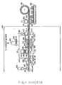
- Figure 1 illustrates an overall view of the manufacturing process to produce second surface optically recordable disks.
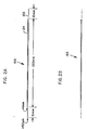
- Figure 2A illustrates a sideview of the second surface optically recordable disk on severance from laminate sheet.
- Figure 2B illustrates the completed optical disk with trimmed and sealed edge/periphery.
- FIG. 1 The conceptual method for manufacture of second surface optically recordable media is, in large part, illustrated in Figure 1.
- the flow schematic of Figure 1 illustrates an overall view of the process and system claimed herein. It should be understood that various laminate layers described in the system of Figure 1 are not drawn to relative scale with respect to each other or the mechanisms through which they pass. All laminates are drawn with equal thickness for clarity of illustration.
- FIG. 1 an internal view of a rectangular laminating enclosure 10 is illustrated having a first, second, third and fourth fluid inlets 12,14, 16 and 18 leading to a first, second, third and fourth vacated upper compartments, 20,22,24 and 26, respectively, separated by a first, second and third baffels 28, 30 and 32.
- a first and second combustible gas outputs 31 and 34, respectively, allow for exit of nonuseable gases which may be flared at a distal ends thereof 33 and 35.
- First fluid, inlet 12 is coupled through a first regulator 36, with flow feedback 37, to a tetraethoxy silane (TEOS) solution, [SiO(C2H5)4], [Si(C2H5O)4] liquid with or without other metal alkoxide additives dissolved in an appropriate organic solvent.
- TEOS tetraethoxy silane
- aluminium isopropoxide [Al(C3H5O)3], sodium methoxide [Na(CH3O)] lithium ethoxide [Li(C2H5O)], or calcium methoxide [Ca(CH3O)2]
- solvents for the foregoing solids might be methanol (CH3OH), ethanol (C2H5OH), propanol (C3H7OH), butanol (C4H9OH), or some suitable combination of the foregoing.
- the purpose of the metal alkoxide additives is to adjust physical or chemical properties of the glass. An example would be to match the thermal expansion of the glass to that of aluminium.
- Second and fourth inlets 14 and 18 are coupled through a second regulator 40, with flow feedback 41, to an inert gas argon (Ar) source 42.
- Third inlet 16 is coupled through a third regulator 44, with flow feedback 45, to a triisobutyl aluminium (TIBA), [A](C2H5)3],source 46.
- TIBA triisobutyl aluminium
- a dual-sprocket ladder chain-drive 48 travelling in the direction of indicated arrow 49 circulates throughout a body of molten metal such as tin (Sn) 50 in a lower compartment 51 of laminating enclosure 10.
- Chain drive 48 may be regulated by servo means 52 coupled to other components of the overall laminating process for proper timing as would be conventional in the art.
- Lower compartment 51 is provided with a forward indent 54 that is designed to be tangential to the surface of circulating molten metal 50 such that a forward meniscus 56 will not be allowed to interfere with lamination initiation thereon.
- An existing miniscus 58 at an exit window 60 of enclosure 10, allows separation of a lamination formed on molten metal 50 surface while passing through and supported by superior and inferior air bearings 62 and 64, respectively.
- Lower compartment 51, and molten metal 50, therein, are maintained at an elevated temperature by first and second transformers 66 and 68 which are independently regulated by a first and second variacs 70 and 72, respectively, such that the forward volume of molten metal 50 may be maintained at a higher temperature by transformer 66, relative to the exit volume heated by transformer 68.
- transformer 66 and 68 actually pass through metal 50, which in the preferred embodiment is tin, and due to resistance to relative current flow therein, generates the respective heat.
- TEOS tetraethoxy silane solution
- Thickness of the laminate is in direct proportion to the volume flow of TEOS and the speed of the moving surface of molten tin 50, which in turn is maintained in motion by chaindrive 48.
- An inert gas which is argon (Ar) in the preferred embodiment, is applied to second compartment 22 at a pressure somewhat higher than any gas pressure in first compartment 20, such that the multitude of low atomic weight gases given off in the pyrolysis of TEOS to form glass laminate 13, is vented through first exit pipe 31 and flared at 33.
- the flow of molten tin 50, from first, second and third compartments 20, 22 and 24, toward exit window 60 caused by chain drive 48, carries glass laminate with a desired thickness determined by temperature of molten tin, by volume flow of TEOS, by speed of chain drive 48, by length of first compartment 20, and by rate of dual laminate 11 as it is pulled from enclosure 10.
- laminate 13 passes through second compartment 22, containing inert gas, into third compartment 24 where a gas flow of triisobutyl aluminium (TIBA) is applied to the surface thereof.
- TIBA triisobutyl aluminium
- a designed thickness of 25 micrometers (um) of aluminium laminate 15 is determined by temperature, by volume flow of TIBA, by speed of chain drive 48 and accompanying flow of tin, by length of third compartment 24, and by rate of flow of dual laminate 11, as it is pulled fro-enclosure 10.
- flow of argon (Ar) gas in fourth compartment 26 not only maintains TIBA and pyrolized gas derivatives thereof, in third compartment 24, but also keeps contaminates, exterior to enclosure 10, out of enclosure 10, and thereby maintains a clean laminating process.
- Aluminium reflective laminate 15 having reflectivity characteristics of at least 80%, is an aluminium laminate in the preferred embodiment of approximately 25 micrometers in thickness but may also be any reflective metal, metallic compound or alloy.
- reflective laminate 15 is derived in the preferred embodiment from the precipitation of pure aluminium (Al) from a gas of triisobutyl aluminium [Al](C4H9)3], flowing upon a body of molten tin, with butane (C4H8) and hydrogen (H2) derivatives given off.
- Composite laminate 11, thusly created exits enclosure 10 by automatically separating from tin meniscus 58 at exit slot 60.
- laminate 11 is first supported by superior and inferior air bearings 62 and 64 respectively, conventional to the art.
- a thickness sensor 74 may be any conventional x-ray, dielectric type or type sensor having the capacity to monitor and assure that a consistent and desired thickness of aluminium reflective laminate and glass laminate are maintained.
- servo 52 having a thickness adjusting mechanism 53, is coupled via dashed lines 76, 78, 80 and 82 to TIBA mixture regulator 44, to argon regulator 40, to TEOS regulator 36 and to tensioning and speed control mechanisims 84 and 86, conventional to the art.
- regulator 44 is opened more to allow a greater flow of TIBA mixture into third compartment 24 of enclosure 10.
- TEOS regulator 36 is opened wider to allow a greater flow of TEOS.
- Composite laminate 11 is next pulled under a dye polymer dispenser 88 where a layer of optically reactive dye polymer 90 is sprayed timely and uniformly across the surface of reflective aluminium layer 15 to complete a process of forming a first layer optically reactive (recordable) laminate sheet.
- Optically reactive layer 90 which is generally in the realm of 100 nanometers (nm) in thickness, is a soluble dye polymer or dye-binder polymer blend, and is illustrated as being sprayed onto reflective layer 15, in a finely atomized spray; however, layer 90, may likewise be applied by rolling or dipping techniques, conventional to the art.
- an adhesive layer 101 is applied by a finely atomized spray of an adhjesive dispenser 103, operated upon by a pressurized nitrogen gas (N2) source 106.
- N2 pressurized nitrogen gas
- dye polymer and adhesive may be combined by use of a similar substance having both characteristics, eg, an adhesive dye polymer.
- first surface optically recordable laminate sheet 102 comprising optically active layer 90, reflective layer 15, and glass substratum, 134, is next passed through a partially evacuated cover placement and embossing compartment 104.
- laminate sheet 102 On entering compartment 104, laminate sheet 102, first passes through a superior and an inferior stationary triple compartment entrance gland seals, 106 and 108 respectively. Entrance gland seals 106 and 108 and exit gland seals 107 and 109, operate to create a partial vacuum within compartment 104.
- an outlet 110 is coupled to a vacuum pump creating a partial vacuum in first gland compartment 112.
- a first gland partition 114 having a small passage therethrough, allows for a creation of a greater vacuum in second gland compartment 116.
- a second gland partition 118 having a small passageway therethrough, allows for creation of an even greater vacuum in third gland compartment 120, which leads to creation of a better vacuum in interior 121 of compressing compartment 104.
- a cover storage and dispensing device 122 positioned within compressing compartment 104, retains a stock of disk shaped covers 124 that are retained and dropped one at a time at regulated intervals by tripping means 126.
- Covers 124 may be in the preferred embodiment 80, 120, 130 or 200 millimeters (mm) in diameter and approximately one (1) mm in thickness.
- Covers 124 may be injection or compression molded, optical grade polycarbonate or polymethylmethacrylate (PMMA) of low birefringence.
- the optical material is first treated for low transmittance of ultraviolet (UV) energy in order that protective cover 124, once mated with optically recordable laminate sheet 102, will not transmit damaging light energy that would decompose the dye polymer comprising the optically active layer of the recordable medium when subjected to an environment of harmful radiation.
- UV energy absorbing material of the hydroxyphenyl benzotriazole class an example of which might be a compound commercially offered under Cyanamid Corporation trademark "Cyasorb,” UV 5411, may be spin coated upon covers 124 or may be an additive to the molding compound itself.
- disk dispenser 122 systematically drops individual covers 124, on adhesive layer 101.
- Laminate sheet 102, with cover 124, is then compressed for permanent bonding and embossing between a superior and an inferior conveyor belt, 128 and 130, respectively.
- a superior and an inferior back plate, 140 and 142 respectively, are fixedly positioned behind conveyor belts 128 and 130, respectively, to guide and maintain position of belts 128 and 130, as they compress and emboss covers 124, into adhesive layer 101, and into optically active layer 90, of laminate sheet 102.
- Second surface optically recordable media 144 exit embossing enclosure 104 through exit gland seals 107 and 109. Although all other gland seals, 106, 108 and 109 are stationary, superior exit gland seal 107, is provided with lifting means 146 to temporarily lift seal 107, as newly formed second surgace optically recordable media 144 exit enclosure 104.
- a slide valve 148 is provided in the intake side of an exhaust blower 150, such that as gland seal 107 is lifted slightly, slide valve 148 is closed. As gland seal 107 is returned to its seat, slide valve 148 is opened allowing exhaust blower 150 to evacuate enclosure 122 once more.
- Cutting means 152 and 154 are basically cylindrical punches in the preferred embodiment but may, of course, be any desired geometrical shape to make a variety of uniquely shaped recordable media for particular applications.
- Superior punch 152 is designed to be the same shape and diameter as covers 124 in the preferred embodiment.
- Punches 152 and 154 function in such manner that as covers 124 and respective embossed portion of laminate sheet 102 are severed from laminate sheet 102, the embossed laminate portion of the individual second surface optically recordable disk 156 thereby formed extends as a lip around the periphery of respective covers 124, attached thereto. Diameter of laminate 102 should be somewhat 23% greater than, diameter of respective covers 124
- the second surface recordable medium 144 is cut from laminate sheet 102, it is converted into a second surface recordable disk 156, and is dropped to a finishing conveyor belt 158.
- Laminate sheet 102, with holes 162, punched therethrough is collected by a tension regulated collection roller 160 for disposal.
- an overall process enclosure 164 the foregoing process is not confined to a cleanroom environment, but within a dirty global environment by virtue of the higher gas pressure inside enclosure 164, than outside thereof.
- laminate sheet 102 comprising substratum glass laminate 13, reflective laminate 15, and reactive laminate 90, as well as covers 124, have been grossly distorted in relative thickness in Figure 1 for purpose of illustration of the overall invention flow process.
- Figure 2 provides, however, a clearer view of the relative dimension and a proper perspective of the semi-finished and finished product, Figure 2a and Figure 2b, respectively.
- a 130 mm cover 124 having a 15 mm extended laminate 102 lip, is subjected to a cutting, trimming and sealing process, conventional in the art.
- Faying surface of cover 124 is conventionally sealed with any of various thermoplastic or thermosetting resins, widely varying in flexibility, used in tough chemical-resistive coatings and adhesives, eg polyurethane, to yield the finished 130 mm, second surface optically recordable disk, illustrated in figure 2b.
Landscapes
- Chemical & Material Sciences (AREA)
- Engineering & Computer Science (AREA)
- Materials Engineering (AREA)
- Organic Chemistry (AREA)
- Chemical Kinetics & Catalysis (AREA)
- Manufacturing & Machinery (AREA)
- Life Sciences & Earth Sciences (AREA)
- General Chemical & Material Sciences (AREA)
- Geochemistry & Mineralogy (AREA)
- Manufacturing Optical Record Carriers (AREA)
Claims (18)
- Ein Laminierverfahren zur Herstellung von Zweitschicht-Medien auf die optische Aufzeichnungen gemacht werden können, dadurch charakterisiert, daß das Verfahren folgende Stufen umfaßt: das Zersetzen einer ersten Flüssigkeit (38) durch Pyrolyse, so daß diese ein festes Glas-Basislaminat (13) bildet; das Zersetzen einer zweiten Flüssigkeit (46) durch Pyrolyse, so daß diese ein festes reflektierendes Laminat (15) bildet, das mit dem genannten Basislaminat (13) verklebt ist; das Überziehen des genannten reflektierenden Laminats (15) mit einem optisch aktiven Laminat (90), so daß eine Erstschicht-Laminatplatte, auf die optische Aufzeichnungen gemacht werden können (102), gebildet wird; das Überziehen des genannten optisch aktiven Laminats (90) mit einem optisch transparenten Klebelaminat (101); das aufeinanderfolgende Auftragen optisch transparenter, UV-hemmender Schichten (124) auf das genannte Klebelaminat (101); das Zusammenpressen und Prägen jeder Schicht (124) mit dem und in das genannte Klebelaminat (101) und das genannte optisch aktive Laminat (90) , so daß diese eine Reihe von Zweitschicht-Medien, auf die optische Aufzeichnungen gemacht werden können (144), bilden; und das Abtrennen jedes individuellen Zweitschicht-Mediums, auf das optische Aufzeichnungen gemacht werden können (144) von der genannten Reihe von Medien, so daß diskrete Zweitschicht-Medien, auf die optische Aufzeichnungen gemacht werden können (156), gebildet werden.
- Ein Laminierverfahren wie nach Anspruch 1, dadurch charakterisiert, daß das genannte Basislaminat (13) durch Extrahieren eines Laminats (13) von amorphem Glas (SiO₂) auf einer fließenden Oberfläche von geschmolzenem Metall (50) durch einen Flüssigkeitsfluß einer Silikatverbindung (38) auf die genannte Schicht, gebildet wird.
- Ein Laminierverfahren wie nach Anspruch 2, dadurch charakterisiert, daß die genannte Silikatverbindung (38) aus Tetraähtoxylsilan besteht.
- Ein Laminierverfahren wie nach Ansprüchen 1 bis 3, dadurch charakterisiert, daß das genannte reflektierende Laminat (15) durch Extrahieren eines Laminats (15) aus reflektivem Metall von einer Verbindung (46) auf das genannte Glaslaminat (13) gebildet wird.
- Ein Laminierverfahren wie nach Anspruch 4, dadurch charakterisiert, daß die genannte organometallische Verbindung (46) aus Triisobutyl-Aluminium besteht.
- Ein Laminierverfahren wie nach einem der vorhergehenden Ansprüche, dadurch charakterisiert, daß das genannte optisch aktive Laminat (90) durch Aufsprühen einer Schicht von Farbpolymer (90) auf das genannte reflektive Laminat (15) gebildet wird.
- Ein Laminierverfahren wie nach einem der vorhergehenden Ansprüche, dadurch charakterisiert, daß das genannte Klebelaminat (101) durch Aufsprühen einer Schicht von Klebstoff auf das genannte reflektive Laminat (15) gebildet wird.
- Ein Laminierverfahren wie nach einem der vorhergehenden Ansprüche, dadurch charakterisiert, daß die genannten Schichten (124) aus spritzgegossenen transparenten Polymeren gebildet werden.
- Ein Laminierverfahren wie nach Anspruch 8, dadurch charakterisiert, daß das transparente Polymer aus Polymethylmethakrylat besteht.
- Ein Laminierverfahren wie nach Anspruch 8, dadurch charakterisiert, daß das transparente Polymer aus Polykarbonat besteht.
- Ein Laminiergerät zur Herstellung von Zweitschicht-Medien, auf die optische Aufzeichnungen gemacht werden können, dadurch charakterisiert, daß es folgendes Umfaßt: Einrichtungen (10,12,36) zur Bildung einer Glas-Basislaminatplatte (13); Einrichtungen (10,16,44), die mit den genannten Einrichtungen zur Bildung des Basislaminats (10,12,36) verbunden sind, um ein reflektierendes Laminat (15) zu bilden und mit der genannten Basislaminatplatte (13) zu verkleben; eine Einrichtung (88), die mit den genannten Einrichtungen zur Bildung des reflektierenden Laminats (10,16,44) verbunden ist, um ein optisch aktives Laminat (90) zu bilden und mit der genannten reflektierenden Laminatplatte (15) zu verkleben und so eine Erstschicht-Laminatplatte, auf die optische Aufzeichnungen gemacht werden können (102), zu bilden; eine Einrichtung (104), die mit der genannten Einrichtung zur Bildung des optisch aktiven Laminats (88) verbunden ist, um nacheinander optisch transparente Ultraviolett (UV) hemmende Schichten (124) von festgelegten geometrischen Größen auf die genannte Erstschicht-Laminatplatte, auf die optische Aufzeichnungen gemacht werden können (102) zu prägen und so eine Vielzahl von Zweitschicht-Medien, auf die optische Aufzeichnungen gemacht werden können (144) zu bilden; und Einrichtungen (152,154), die mit der genannten schichtprägenden Einrichtung (104) verbunden sind, um jedes Zweitschicht-Medium, auf das optische Aufzeichnungen gemacht werden können (144), individuell zu trennen und zu versiegeln und so diskrete Zweitschicht-Medien, auf die optische Aufzeichnungen gemacht werden können (156), zu bilden.
- Ein Laminiergerät wie nach Anspruch 11, dadurch charakterisiert. daß die genannten Basislaminat-bildenden Einrichtungen (10,12,36) einen Behälter (51) umfassen, der einen flüssigen Körper geschmolzenen Metalls (50) hält und Einrichtungen (12,36) zur Verteilung eines Flüssigkeitsflusses einer Verbindung, die Silikon und Sauerstoff enthält (38) auf der Oberfläche des genannten geschmolzenen Metalls (50) enthält, und um die genannte Verbindung durch Pyrolyse zu zersetzen, um ein amorphes Glaslaminat (13) zu extrahieren.
- Ein Laminiergerät wie nach Anspruch 12, dadurch charakterisiert, daß der genannte Behälter (51) weiterhin Einrichtungen (16,44) zur Verteilung eines Flüssigkeitsflußes einer Verbindung, die reflektierendes Metall enthält (46), auf dem genannten Glaslaminat (13) beinhaltet, sowie Einrichtungen, um die genannte Verbindung (46) durch Pyrolyse zu zersetzen, um so eine Metallschicht zu extrahieren, um das genannte reflektierende Laminat (15) zu bilden.
- Ein Laminiergerät wie nach einem der Ansprüche 11 bis 13, dadurch charakterisiert, daß die genannte Einrichtung zur Bildung des optisch aktiven Laminats (88) eine Sprühvorrichtung zur Verteilung eines Farbpolymers (90) umfaßt.
- Ein Laminiergerät wie nach einem der Ansprüche 11 bis 14, dadurch charakterisiert, daß die genannte Einrichtung zur Prägung der Schichten (104) Schichtstapelungs-, Verteilungs- und Komprimiereinrichtungen (122,128,130) umfaßt.
- Ein Laminiergerät wie nach einem der Ansprüche 11 bis 15, dadurch charakterisiert, daß die genannte Trenneinrichtung (152,154) eine Stanzpresse umfaßt
- Ein laminiertes Zweitschicht-Medium, auf das optische Aufzeichnungen gemacht werden können, dadurch charakterisiert, daß es folgendes umfaßt: ein Glas-Basislaminat (13); ein reflektierendes Laminat aus Aluminium (15), das mit dem genannten Basislaminat (13) verklebt ist; ein optisch aktives Laminat aus Farbpolymer (90), das mit dem genannten reflektierenden Laminat (15) verklebt ist; und eine optisch transparente UV hemmende Schicht (124), die mit dem-genannten aktiven Laminat (90) verklebt ist.
- Ein Medium, auf das optische Aufzeichnungen gemacht werden können, wie nach Anspruch 17, dadurch charakterisiert, daß die genannte Schicht aus einer spritzgegossenen Polymethyl-Methakrylat-Platte besteht, die mit bestimmten UV hemmenden Zusätzen behandelt wurde.
Priority Applications (1)
| Application Number | Priority Date | Filing Date | Title |
|---|---|---|---|
| DE69115672T DE69115672D1 (de) | 1991-01-07 | 1991-01-07 | Auf Glas basierende optische Platte und deren Herstellungsverfahren |
Applications Claiming Priority (1)
| Application Number | Priority Date | Filing Date | Title |
|---|---|---|---|
| US07/316,027 US5002622A (en) | 1989-02-27 | 1989-02-27 | Glass based optical disc manufacturing process |
Publications (2)
| Publication Number | Publication Date |
|---|---|
| EP0494479A1 EP0494479A1 (de) | 1992-07-15 |
| EP0494479B1 true EP0494479B1 (de) | 1995-12-20 |
Family
ID=23227148
Family Applications (1)
| Application Number | Title | Priority Date | Filing Date |
|---|---|---|---|
| EP91300096A Expired - Lifetime EP0494479B1 (de) | 1989-02-27 | 1991-01-07 | Auf Glas basierende optische Platte und deren Herstellungsverfahren |
Country Status (2)
| Country | Link |
|---|---|
| US (1) | US5002622A (de) |
| EP (1) | EP0494479B1 (de) |
Families Citing this family (5)
| Publication number | Priority date | Publication date | Assignee | Title |
|---|---|---|---|---|
| EP0627734A1 (de) * | 1993-06-04 | 1994-12-07 | Canon Kabushiki Kaisha | Verfahren zur Herstellung eines optischen Aufzeichnungsmediums |
| US6007888A (en) * | 1998-05-08 | 1999-12-28 | Kime; Milford B. | Directed energy assisted in vacuo micro embossing |
| US20100112355A1 (en) * | 2008-11-06 | 2010-05-06 | Cessna Aircraft Company | Aircraft Transparency |
| ES3006307T3 (en) * | 2013-06-27 | 2025-03-18 | Vitro Flat Glass Llc | Glass manufacturing system incorporating an optical low-coherence interferometry assembly |
| US11833503B2 (en) | 2021-12-07 | 2023-12-05 | Insilixa, Inc. | Methods and compositions for surface functionalization of optical semiconductor-integrated biochips |
Family Cites Families (6)
| Publication number | Priority date | Publication date | Assignee | Title |
|---|---|---|---|---|
| US3847585A (en) * | 1973-01-08 | 1974-11-12 | Dow Chemical Co | Method for the preparation of multilayer optical filters |
| US4499477A (en) * | 1983-03-14 | 1985-02-12 | Minnesota Mining And Manufacturing Company | Cover assembly for optical recording medium |
| JPS60177449A (ja) * | 1984-02-22 | 1985-09-11 | Daicel Chem Ind Ltd | 光学式情報記録担体 |
| US4600682A (en) * | 1984-07-06 | 1986-07-15 | Storage Technology Corporation | Optical storage structure |
| US4861656A (en) * | 1986-12-24 | 1989-08-29 | Tdk Corporation | Optical recording medium |
| US4871601A (en) * | 1987-02-25 | 1989-10-03 | Canon Kabushiki Kaisha | Optical information recording carrier |
-
1989
- 1989-02-27 US US07/316,027 patent/US5002622A/en not_active Expired - Fee Related
-
1991
- 1991-01-07 EP EP91300096A patent/EP0494479B1/de not_active Expired - Lifetime
Also Published As
| Publication number | Publication date |
|---|---|
| EP0494479A1 (de) | 1992-07-15 |
| US5002622A (en) | 1991-03-26 |
Similar Documents
| Publication | Publication Date | Title |
|---|---|---|
| US5464710A (en) | Enhancement of optically variable images | |
| US20050160893A1 (en) | Method and apparatus for forming microstructures on polymeric substrates | |
| US5080947A (en) | Information recording medium | |
| NL8101298A (nl) | Materiaal voor het opnemen en weergeven. | |
| US5087510A (en) | Electrolessly deposited metal holograms | |
| US5002622A (en) | Glass based optical disc manufacturing process | |
| US4964934A (en) | Optical disk manufacturing process | |
| US6210609B1 (en) | Method of manufacturing optical recording medium | |
| WO2004000533A1 (en) | Embossing apparatus, method of use thereof and resulting article | |
| US5426013A (en) | Optical recording media containing uniform partially oxidized metal layer | |
| JPH07262627A (ja) | 多層光磁気記録媒体 | |
| EP0477447B1 (de) | Verfahren zur Herstellung einer optischen Speichervorrichtung | |
| JPH04232627A (ja) | ガラスをベースにした光ディスク及びその製造方法 | |
| US20070014886A1 (en) | Method and apparatus for forming microstructures on polymeric substrates | |
| US7335521B2 (en) | Method for the production of multilayer discs | |
| Bornemann et al. | Changes of the optical properties of “smooth” silver by silver deposits at low temperatures | |
| JP2581036B2 (ja) | 光記録媒体 | |
| JPS6275948A (ja) | 光記録媒体の製造方法 | |
| JPS6058529B2 (ja) | 着色磁気記録体 | |
| JPS5945009B2 (ja) | 蒸着フイルムの製造装置 | |
| JPH0257387A (ja) | 光メモリー媒体 | |
| JPH0690812B2 (ja) | 光記録媒体の製造方法 | |
| JPS60187950A (ja) | 光記録媒体 | |
| JPS6045271B2 (ja) | 真空蒸着装置 | |
| JPH04147445A (ja) | 第2表面光学的記憶装置を製造する方法 |
Legal Events
| Date | Code | Title | Description |
|---|---|---|---|
| PUAI | Public reference made under article 153(3) epc to a published international application that has entered the european phase |
Free format text: ORIGINAL CODE: 0009012 |
|
| AK | Designated contracting states |
Kind code of ref document: A1 Designated state(s): DE FR GB IT NL |
|
| 17P | Request for examination filed |
Effective date: 19921130 |
|
| 17Q | First examination report despatched |
Effective date: 19940405 |
|
| GRAA | (expected) grant |
Free format text: ORIGINAL CODE: 0009210 |
|
| AK | Designated contracting states |
Kind code of ref document: B1 Designated state(s): DE FR GB IT NL |
|
| PG25 | Lapsed in a contracting state [announced via postgrant information from national office to epo] |
Ref country code: IT Free format text: LAPSE BECAUSE OF FAILURE TO SUBMIT A TRANSLATION OF THE DESCRIPTION OR TO PAY THE FEE WITHIN THE PRE;WARNING: LAPSES OF ITALIAN PATENTS WITH EFFECTIVE DATE BEFORE 2007 MAY HAVE OCCURRED AT ANY TIME BEFORE 2007. THE CORRECT EFFECTIVE DATE MAY BE DIFFERENT FROM THE ONE RECORDED.SCRIBED TIME-LIMIT Effective date: 19951220 Ref country code: NL Free format text: LAPSE BECAUSE OF FAILURE TO SUBMIT A TRANSLATION OF THE DESCRIPTION OR TO PAY THE FEE WITHIN THE PRESCRIBED TIME-LIMIT Effective date: 19951220 Ref country code: FR Effective date: 19951220 |
|
| REF | Corresponds to: |
Ref document number: 69115672 Country of ref document: DE Date of ref document: 19960201 |
|
| PGFP | Annual fee paid to national office [announced via postgrant information from national office to epo] |
Ref country code: FR Payment date: 19960221 Year of fee payment: 6 |
|
| PGFP | Annual fee paid to national office [announced via postgrant information from national office to epo] |
Ref country code: DE Payment date: 19960223 Year of fee payment: 6 Ref country code: NL Payment date: 19960223 Year of fee payment: 6 |
|
| PG25 | Lapsed in a contracting state [announced via postgrant information from national office to epo] |
Ref country code: DE Effective date: 19960321 |
|
| EN | Fr: translation not filed | ||
| NLV1 | Nl: lapsed or annulled due to failure to fulfill the requirements of art. 29p and 29m of the patents act | ||
| PLBE | No opposition filed within time limit |
Free format text: ORIGINAL CODE: 0009261 |
|
| STAA | Information on the status of an ep patent application or granted ep patent |
Free format text: STATUS: NO OPPOSITION FILED WITHIN TIME LIMIT |
|
| 26N | No opposition filed | ||
| PGFP | Annual fee paid to national office [announced via postgrant information from national office to epo] |
Ref country code: GB Payment date: 19961220 Year of fee payment: 7 |
|
| PG25 | Lapsed in a contracting state [announced via postgrant information from national office to epo] |
Ref country code: GB Free format text: LAPSE BECAUSE OF NON-PAYMENT OF DUE FEES Effective date: 19980107 |
|
| GBPC | Gb: european patent ceased through non-payment of renewal fee |
Effective date: 19980107 |