EP0494471B1 - Schlösser - Google Patents
Schlösser Download PDFInfo
- Publication number
- EP0494471B1 EP0494471B1 EP91203319A EP91203319A EP0494471B1 EP 0494471 B1 EP0494471 B1 EP 0494471B1 EP 91203319 A EP91203319 A EP 91203319A EP 91203319 A EP91203319 A EP 91203319A EP 0494471 B1 EP0494471 B1 EP 0494471B1
- Authority
- EP
- European Patent Office
- Prior art keywords
- key
- keyway
- bit
- transmission element
- lock
- Prior art date
- Legal status (The legal status is an assumption and is not a legal conclusion. Google has not performed a legal analysis and makes no representation as to the accuracy of the status listed.)
- Expired - Lifetime
Links
Images


Classifications
-
- G—PHYSICS
- G07—CHECKING-DEVICES
- G07C—TIME OR ATTENDANCE REGISTERS; REGISTERING OR INDICATING THE WORKING OF MACHINES; GENERATING RANDOM NUMBERS; VOTING OR LOTTERY APPARATUS; ARRANGEMENTS, SYSTEMS OR APPARATUS FOR CHECKING NOT PROVIDED FOR ELSEWHERE
- G07C9/00—Individual registration on entry or exit
- G07C9/00174—Electronically operated locks; Circuits therefor; Nonmechanical keys therefor, e.g. passive or active electrical keys or other data carriers without mechanical keys
- G07C9/00309—Electronically operated locks; Circuits therefor; Nonmechanical keys therefor, e.g. passive or active electrical keys or other data carriers without mechanical keys operated with bidirectional data transmission between data carrier and locks
-
- G—PHYSICS
- G07—CHECKING-DEVICES
- G07C—TIME OR ATTENDANCE REGISTERS; REGISTERING OR INDICATING THE WORKING OF MACHINES; GENERATING RANDOM NUMBERS; VOTING OR LOTTERY APPARATUS; ARRANGEMENTS, SYSTEMS OR APPARATUS FOR CHECKING NOT PROVIDED FOR ELSEWHERE
- G07C9/00—Individual registration on entry or exit
- G07C9/00174—Electronically operated locks; Circuits therefor; Nonmechanical keys therefor, e.g. passive or active electrical keys or other data carriers without mechanical keys
- G07C2009/00753—Electronically operated locks; Circuits therefor; Nonmechanical keys therefor, e.g. passive or active electrical keys or other data carriers without mechanical keys operated by active electrical keys
- G07C2009/00769—Electronically operated locks; Circuits therefor; Nonmechanical keys therefor, e.g. passive or active electrical keys or other data carriers without mechanical keys operated by active electrical keys with data transmission performed by wireless means
- G07C2009/00777—Electronically operated locks; Circuits therefor; Nonmechanical keys therefor, e.g. passive or active electrical keys or other data carriers without mechanical keys operated by active electrical keys with data transmission performed by wireless means by induction
-
- Y—GENERAL TAGGING OF NEW TECHNOLOGICAL DEVELOPMENTS; GENERAL TAGGING OF CROSS-SECTIONAL TECHNOLOGIES SPANNING OVER SEVERAL SECTIONS OF THE IPC; TECHNICAL SUBJECTS COVERED BY FORMER USPC CROSS-REFERENCE ART COLLECTIONS [XRACs] AND DIGESTS
- Y10—TECHNICAL SUBJECTS COVERED BY FORMER USPC
- Y10T—TECHNICAL SUBJECTS COVERED BY FORMER US CLASSIFICATION
- Y10T70/00—Locks
- Y10T70/70—Operating mechanism
- Y10T70/7051—Using a powered device [e.g., motor]
- Y10T70/7062—Electrical type [e.g., solenoid]
- Y10T70/7068—Actuated after correct combination recognized [e.g., numerical, alphabetical, or magnet[s] pattern]
- Y10T70/7073—Including use of a key
- Y10T70/7079—Key rotated [e.g., Eurocylinder]
-
- Y—GENERAL TAGGING OF NEW TECHNOLOGICAL DEVELOPMENTS; GENERAL TAGGING OF CROSS-SECTIONAL TECHNOLOGIES SPANNING OVER SEVERAL SECTIONS OF THE IPC; TECHNICAL SUBJECTS COVERED BY FORMER USPC CROSS-REFERENCE ART COLLECTIONS [XRACs] AND DIGESTS
- Y10—TECHNICAL SUBJECTS COVERED BY FORMER USPC
- Y10T—TECHNICAL SUBJECTS COVERED BY FORMER US CLASSIFICATION
- Y10T70/00—Locks
- Y10T70/70—Operating mechanism
- Y10T70/7441—Key
- Y10T70/778—Operating elements
- Y10T70/7791—Keys
- Y10T70/7904—Magnetic features
Definitions
- the present invention relates to locks and more particularly to "electronic" key locks of the kind where a code is received by the lock from a proper key by way of inductive coupling between the two.
- Inductively-coupled key locks are relatively well known, at least in the patents literature, as exemplified by DE-2634303, EP-0115747, GB-2158870, GB-2174452, US-4549176, US-4602253 and WO-88/03594.
- the lock generates an alternating magnetic field in a region into which the key is brought, the key having circuit elements which control an inductive transmission element on the key to modulate or add to the field generated by the lock in such a way as to enable detection by the lock of a code programmed into the key.
- the power for the circuit elements of the key is derived by rectification of the voltage induced by the alternating field of the lock.
- the present invention is therefore concerned with an "electronic" lock which can resemble a conventional mechanical cylinder lock in that it comprises a housing bearing a rotatable barrel with a keyway, into which the key is inserted and turned in order to retract the associated bolt or other such locking member.
- a lock of this style operating on the inductive coupling principle, more particularly for vehicle doors, is disclosed in GB-2174452.
- the induction elements of both lock and key comprise a respective coil with a soft iron core.
- the lock coil is mounted longitudinally in a bushing at the end of the barrel, to one side of the keyway, while the key coil is mounted longitudinally in its tip, so that when the key is fully inserted in the barrel the two coils lie side-by-side, with their cores in parallel. It is evident that in an arrangement such as that, however, only a partial inductive coupling between the two coils can be achieved, in the sense that much of the magnetic flux generated by either coil will follow a path which does not pass through the other. In consequence, the total magnetic flux and energising power requirements of the lock are higher than they need be if a more efficient coupling of the inductive elements were achieved.
- the invention therefore resides in a lock comprising: a housing; a barrel defining a keyway borne rotatably in the housing and adapted to receive and be turned by a proper coded key; reading means adapted to receive the code from a proper key when inserted in said keyway, by way of inductive coupling with a code transmission element of the key; and means for controlling the operation of the lock whereby to enable the retraction of a bolt or other such locking member by turning of the barrel when a proper key code is received via said reading means; wherein the reading means includes a coil for generating an alternating magnetic field in a region of said keyway and a coil (preferably the same as the first-mentioned coil) for detecting a modulation or addition to said field by the transmission element of a proper key when located in said region of the keyway; said coil(s) surrounding part of a toroidal (i.e.
- ring-like) magnetically-permeable core structure which defines a gap spanning the aforesaid region of said keyway; and wherein said core structure is collectively defined at least by a first frusto-toroidal part mounted in said housing, around which said coil(s) wind, and which presents two ends in proximity to said barrel, and by two further parts mounted in the barrel, one to either side of the aforesaid region of said keyway, and which are juxtaposed to respective ends of said first part when the barrel is in the key-reading position relative to the housing.
- the magnetic flux generated/received by the coil(s) in the lock housing is concentrated in the toroidal structure collectively defined by the aforesaid magnetically-permeable (preferably ferrite) parts in the housing and barrel, and can pass across the region of the keyway wherein the transmission element of the key is located with only minor losses.
- This maximisation of the flux coupling between lock and key thereby provides a solution to the power consumption and EMC requirements discussed above. It also means that relatively small and simple coils can be used in the lock housing and in the transmission element of the key, thereby minimising their cost and facilitating the implementation of an on-chip key coil as proposed in WO-88/03594 if desired.
- minimising the required size of the key coil minimises any problems of weakening the key by incorporating that element and minimises the chip cost (in the case of an on-chip coil) because the latter is directly related to the amount of chip area.
- chip cost in the case of an on-chip coil
- the invention also resides in the combination of a lock according to the above-defined first aspect of the invention with a key having a bit for insertion into the aforesaid keyway and which bears an inductive transmission element for modulating or adding to the aforesaid magnetic field, the transmission element being positioned in said bit so as to pass into the aforesaid region of the keyway when the bit is so inserted.
- the invention also resides in a key for use with a lock according to the above-defined first aspect of the invention, the key comprising a bow portion and a bit portion; the bit portion being of non-circular cross-section for transmitting rotation to the barrel of a said lock when inserted into the keyway thereof; the bit portion bearing an inductive code transmission element in the form of a coil wound about an axis transverse to the longitudinal axis of the bit portion and parallel to the direction of magnetic flux passage across a said keyway in use of the reading means of a said lock; said code transmission element being mounted in a recess formed in the bit portion of the key and an element or elements of magnetically-permeable material being mounted in said recess to one or both sides of said code transmission element to define part(s) of the magnetic circuit which in use links said code transmission element to a said reading means.
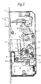
- the illustrated lock is of mortise style having a casing 1 and a forend 2 through which extend a dead bolt 3 and a latch bolt 4.
- Extension and retraction of the dead bolt 3 is in response to rotation in an appropriate sense of an internal thrower 5 having a radial lug 6 which drives the bolt through the agency of a runner 7 moving along an arcuate track, the geometry of the runner/bolt relationship being such as to deadlock the bolt against end pressure when thrown.
- Retraction of the latch bolt 4 is in response to the turning of a cam 8 by means of external handles (not shown) and is likewise accomplished, via a linkage 9, by rotation of the thrower 5 to withdraw the dead bolt.
- the mechanism is of conventional design much practised by the present applicants.
- each such unit has a rotatable barrel 11 with a keyway 12 and, at its inner end, a drive socket 13 whereby to turn the thrower 5.
- a reading head for transducing a code signal from a proper key when inserted therein by way of an inductively-coupled transponder method, e.g. as described in WO-88/03594 and the preferred structure of which is more fully described below.
- Electrical energy for the processor, reading heads and release mechanism is supplied via a lead 20 from a battery pack (not shown) housed in another mortice in the door.
- Additional physical protection for the bolt runner 7, release mechanism 17/18/19 and at least that part 16A of the PCB 16 which mounts an interface circuit between the processor and the electromagnet 17 is provided by hardened steel anti-drill plates 21 located to each side of the lock case 1.
- the interface circuit on PCB part 16A is directly connected with the electromagnet 17 by a cable (not shown) situated between these anti-drill plates.
- a key 22 of the proper form for use with this lock is shown in Figure 3. It comprises a preferably metal blank of e.g. nickel-silver, brass or aluminium, defining bow 23 and bit 24 portions, with a transverse aperture 25 through the bow near to its tip and a narrow transverse gap 26 extending from that aperture to the tip.
- an integrated circuit chip 27 (see Fig. 5) which defines the whole of the key electronics and which is sandwiched between two pads of ferrite 28.
- the assembly of chip 27 and ferrite pads 28 is secured by an epoxy resin or other inert filler 29 which fills also the gap 26.
- the material 29 preferably surrounds all four edges of the chip/ferrite assembly 27/28 between the metal blank to cushion that assembly from the effect of mechanical shocks e.g. if the key is dropped onto a hard floor.
- the chip 27 includes inter alia a memory programmed with an identification or authorisation code which when transferred to the processor of the lock enables release of the thrower 5 for turning by the respective barrel 11 as indicated above.
- the key may also include one or more drillings 39 for cooperation with conventional pin tumblers (not shown) acting between the barrels 11 and housings 30 for indexing the key insertion and withdrawing position, preventing the barrel from being turned unless the key is fully inserted (and preventing the key from being removed until the barrel has been fully turned), and possibly providing mechanical differs between different locks and their keys.
- the principal and essential code-bearing element of the key is the IC chip 27.
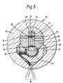
- each cylinder unit 10 comprises a housing 30 of die-cast alloy, e.g. Mazak, or possibly of plastics, in which is journalled the respective barrel 11 of e.g. brass or again possibly plastics.
- a U-shaped ferrite element 31 mounted within the housing at a selected axial distance from its front face is a U-shaped ferrite element 31.
- This is embedded in the housing 30 in epoxy resin or other inert filler 32 and has its two ends juxtaposed to the barrel 11.
- a field-generating and detection coil 33 Wound around one of the limbs of this U, close to the barrel, is a field-generating and detection coil 33, connected by wires 34 to an associated oscillator and detection circuit (not shown).
- the barrel 11 also incorporates two ferrite elements 35 at the same axial position as the housing element 31.
- the elements 35 extend from either side of the keyway 12 to the periphery of the barrel so as to be juxtaposed to respective ends of the element 31 when the barrel is in the key-insertion position shown in the Figures.
- the ferrite elements 35 are electrically isolated therefrom by respective plastics inserts 36 (and which prevent the gap 26 in the key tip from being short-circuited by the metal barrel when the gap 26 just passes the ferrites 35 during insertion of the key).
- a microswitch in the respective housing 30 is depressed which actuates the aforesaid oscillator to supply a high frequency (typically 10MHz) energising current to the coil 33, which induces a corresponding alternating magnetic field in the ferrite element 31.
- a high frequency typically 10MHz
- the juxtaposed ferrite elements 35 will act as extensions to the U-shaped element 31 and define collectively with that element a toroidal core structure with an air gap spanning a localised region of the keyway 12 at a selected axial distance from its entrance.
- the magnetic flux generated by the coil 33 is concentrated in this core structure and passes across that region of the keyway with little loss.
- the relative magnetic permeability of the material in elements 31 and 35 is preferably at least 100 times that of free space, for a ferrite with low loss at the chosen frequency.
- the axial distance of the ferrite core structure 31/35 along the keyway 12 is less than the axial distance along the key bit 24 of the chip 27 from the stop shoulder 37 which defines the limit of insertion of the key. Accordingly, the chip 27 and its flanking ferrite pads 28 pass through the alternating magnetic field between the ferrite elements 35 of the barrel before the key is fully inserted, and in the course of this passage the key code is read. More particularly, the key chip 27 bears an integrated coil as its inductive transmission element, wound in a plane at right angles to the magnetic flux passing across the keyway and positioned for maximum coupling with the field generated by the housing coil 33.
- the coil on chip 27 is located symmetrically in the key, so the latter is reversible in the sense of its orientation for insertion in the keyway.
- the presence of the gap 26 in the key tip prevents the metal of the key blank surrounding the chip 27 from acting as a shorted turn around the key coil, which would otherwise introduce a high loss; (in the alternative a high-strength plastics blank could be used).
- the voltage induced in the key coil by the alternating magnetic field passing across the keyway is rectified to power the active components of the integrated circuit and its frequency, suitably divided, acts as a clock for logic circuitry which drives a shift register containing the identification code data from the aforesaid memory.
- This data is applied to the key coil so as to modulate or add to the field generated in the keyway by the housing coil 33 and the key code is derived in the lock by a detector circuit on the PCB 16 which is connected to the coil 33. Further details of the operation of the electronics to transfer the code from the key to the lock can be found in WO-88/03594.
- the key code is read in this way before the key is fully inserted in order to give the lock electronics time to determine the validity of the code and to give the electromagnet 17 of the release mechanism time to build up its attraction force to a maximum before the user of the key will begin turning of the barrel 11.
- the ferrite pads 28 on the key act as further extensions of the toroidal magnetic core structure 31/35 during insertion of the key, to further concentrate the alternating field in the region of the key coil.
- This material is hard and wear-resistant and also provides good physical protection to the IC chip 27.
- These ferrite pads on the key are not an essential feature of the invention, however, and in other embodiments one or both may be omitted, depending on the permissible width of the air gap in the overall toroidal core structure. Neither is the use of an on-chip key coil essential, and in other embodiments a discrete wire coil may be employed in the key in an equivalent location to the chip 27 illustrated in the Figures.
Landscapes
- Computer Networks & Wireless Communication (AREA)
- Physics & Mathematics (AREA)
- General Physics & Mathematics (AREA)
- Engineering & Computer Science (AREA)
- Lock And Its Accessories (AREA)
- Switch Cases, Indication, And Locking (AREA)
- Glass Compositions (AREA)
- Devices For Conveying Motion By Means Of Endless Flexible Members (AREA)
- Reciprocating, Oscillating Or Vibrating Motors (AREA)
- Electrophonic Musical Instruments (AREA)
- Eye Examination Apparatus (AREA)
- Hydrogenated Pyridines (AREA)
- Pharmaceuticals Containing Other Organic And Inorganic Compounds (AREA)
- Near-Field Transmission Systems (AREA)
- Adjustment Of Camera Lenses (AREA)
- Transition And Organic Metals Composition Catalysts For Addition Polymerization (AREA)
- Switches With Compound Operations (AREA)
- Pens And Brushes (AREA)
- Holders For Apparel And Elements Relating To Apparel (AREA)
Claims (20)
- Schloß mit einem Gehäuse (30); einem Zylinder (11), welcher eine drehbar in dem Gehäuse (30) gelagerte Schlüsselführung (12) aufweist und einen passenden, codierten Schlüssel (22) aufnehmen und von diesem gedreht werden kann; einer Lesevorrichtung (16, 33) zur Aufnahme des Codes von einem passenden Schlüssel (22), wenn dieser in die Schlüsselführung (12) eingeführt wird, über induktive Kopplung mit einem Codeübertragungselement (27) des Schlüssels; und einer Vorrichtung (16, 17) zur Steuerung des Betriebs des Schlosses, um die Rückziehung des Bolzens (3) oder eines anderen Verriegelungsbauteils durch Drehung des Zylinders (11) zu ermöglichen, wenn ein passender Schlüsselcode von der Lesevorrichtung empfangen wird; wobei die Lesevorrichtung eine Spule (33) zur Erzeugung eines alternierenden Magnetfeldes in einem Bereich der Schlüsselführung (12) aufweist und eine Spule (33) zur Detektion einer Modulation oder Addition zu diesem Feld durch das Übertragungselement (27) eines passenden Schlüssels, wenn sich dieser in dem genannten Bereich der Schlüsselführung (12) befindet; dadurch gekennzeichnet, daß die oder jede Spule (33) einen Teil einer toroidalen magnetisch permeablen Kernstruktur (31, 35) umgibt, welcher eine den vorgenannten Bereich der Schlüsselführung überspannende Lücke definiert; wobei diese Kernstruktur kollektiv gebildet wird aus mindestens einem ersten geschlitzt toroidalen Teil (31) in dem Gehäuse (30), um welches die oder jede Spule (33) gewickelt ist und welches zwei dem Zylinder (11) benachbarte Enden aufweist, sowie durch zwei weitere Teile (35) in dem Zylinder (11), jedes auf einer Seite des vorgenannten Bereichs der Schlüsselführung (12), welche entsprechenden Enden des ersten Teils (31) gegenüber liegen, wenn der Zylinder (11) sich bezüglich des Gehäuses (30) in der Schlüsselablesestellung befindet.
- Schloß nach Anspruch 1, wobei die erstgenannten und die zweitgenannten Spulen die gleiche Spulenstruktur (33) aufweisen.
- Schloß nach einem der Ansprüche 1 oder 2, wobei die oder jede Spule (33) jeweils im Bereich eines der Enden des geschlitzt toroidalen Teils (31) um dieses gewickelt ist.
- Schloß nach einem der voranstehenden Ansprüche, wobei die Kernstruktur (31, 35) aus Ferritmaterial besteht.
- Schloß nach einem der voranstehenden Ansprüche, wobei der Hauptbereich des Zylinders (11) aus Metall besteht und die beiden weiteren Teile (35) der Kernstruktur von Einsätzen (36) aus elektrisch nichtleitfähigem Material, welche in dem Zylinder (11) angebracht sind, gelagert werden.
- Schloß nach einem der voranstehenden Ansprüche in Kombination mit einem Schlüssel (22) mit einer Spitze (24) zur Einführung in die vorgenannte Schlüsselführung (12), welcher ein induktives Übertragungselement (27) zur Modulation oder Addition zu dem vorgenannten Magnetfeld aufweist und dieses Übertragungselement (27) in der Spitze (24) so angeordnet ist, daß es den vorgenannten Bereich der Schlüsselführung (12) passiert, wenn die Spitze (24) eingeführt wird.
- Kombination nach Anspruch 6, wobei der Abstand des Übertragungselements (27) entlang der Schlüsselspitze (24) so mit dem Abstand dieses Bereichs entlang der Schlüsselführung (12) in Bezug steht, daß das Übertragungselement (27) diesen Bereich durchläuft, um die Aufnahme des Codes von dem Schlüssel (22) durch die Lesevorrichtung (16, 33) zu ermöglichen vor die Spitze (24) vollständig in die Schlüsselführung (12) eingeführt wurde.
- Kombination nach einem der Ansprüche 6 oder 7, wobei das Übertragungselement (27) des Schlüssels benachbart zu einem oder zwei weiteren Teilen (28) der toroidalen Kernstruktur angeordnet ist, welche sich in der Schlüsselspitze (24) an einer oder beiden Seiten des Übertragungselements (27) befinden und entsprechend gegenüberliegenden einem oder beiden der genannten Teile (35) der in dem Zylinder (11) angebrachten Kernstruktur, wenn die Schlüsselspitze (24) in die Schlüsselführung (12) eingeführt wird.
- Kombination nach einem der Ansprüche 6 bis 8, wobei das Übertragungselement (27) des Schlüssels (22) eine Spule aufweist, welche in einer Ebene um eine zu der Längsachse der Schlüsselspitze (24) transversale Achse gewickelt ist und senkrecht zur Richtung des magnetischen Flusses über den Bereich der Schlüsselführung (12) orientiert ist, wenn die Schlüsselspitze (24) in die Schlüsselführung (12) eingeführt ist.
- Kombination nach Anspruch 9, wobei die Schlüsselspitze (24) im Querschnitt flach ist und das Übertragungselement (27) darin benachbart zum Ende der Schlüsselspitze und parallel zu dessen Längsseiten angebracht ist.
- Kombination nach Anspruch 10, wobei der Hauptteil der Schlüsselspitze (24) aus Metall besteht, die das Übertragungselement (27) umgebende Metallstruktur jedoch an mindestens einer Stelle unterbrochen (26) ist, um nicht als Kurzschluß zu wirken.
- Kombination nach einem der Ansprüche 6 bis 11, wobei das Übertragungselement des Schlüssels (22) als integrales Element eines integrierten Schaltkreises (27) ausgebildet ist, welcher auch Schaltungselmente zur Speicherung und zum Wiederauffinden des Codes aufweist.
- Schlüssel (22) zur Verwendung mit einem Schloß nach einem der Ansprüche 1 bis 5, mit einem Griffbereich (23) und einem Spitzenbereich (24); wobei der Spitzenbereich (24) einen nichtkreisförmigen Querschnitt zur Übertragung einer Drehung auf den Zylinder (11) des Schlosses aufweist, wenn sich der Schlüssel in dessen Schlüsselführung (12) befindet; wobei der Spitzenbereich (24) ein induktives Codeübertragungselement (27) in Form einer Spule aufweist, welche um eine zur Längsachse des Spitzenbereichs (24) transversale Achse gewickelt ist und parallel zur Richtung des magnetischen Flusses über die Schlüsselführung (12) während des Gebrauchs der Lesevorrichtung (16, 33) des Schlosses verläuft; wobei das Codeübertragungselement (27) in einer Ausnehmung (25) in dem Spitzenbereich (24) des Schlüssels (22) angeordnet ist und ein oder mehrere Elemente aus magnetisch permeablem Material (28) in dieser Ausnehmung (25) an einer oder beiden Seiten des Codeübertragungselements (27) angeordnet sind, um ein oder mehrere Teile der magnetischen Schaltung zu bilden, welche während des Gebrauchs das Codeübertragungselement (27) mit der Lesevorrichtung (16, 33) verbinden.
- Schlüssel nach Anspruch 13, wobei der Spitzenbereich (24) einen länglichen Querschnitt aufweist und das Codeübertragungselement (27) darin in einer Ebene parallel zu dessen längerer Ausdehnung angeordnet ist.
- Schlüssel nach einem der Ansprüche 13 oder 14, wobei der Spitzenbereich (24) aus Metall besteht und das Codeübertragungselement (27) und das oder jedes Element aus magnetisch permeablem Material (28) von dem Metall des Spitzenbereichs (24) isoliert sind.
- Schlüssel nach Anspruch 15, wobei das die Ausnehmung (25) umgebende Metall des Spitzenbereiches mindestens an einer Stelle (26) unterbrochen ist, um nicht als Kurzschlußstrecke zu wirken.
- Schlüssel nach einem der Ansprüche 13 oder 14, wobei der Spitzenbereich aus Kunststoff besteht.
- Schlüssel nach einem der Ansprüche 13 bis 17, wobei das Codeübertragungselement als integrales Element eines integrierten Schaltkreises (27) ausgeführt ist, welcher auch Schaltungen für die Speicherung und den Abruf dieses Codes aufweist.
- Schlüssel nach einem der Ansprüche 13 bis 18, wobei das Codeübertragungselement als flacher Chip (27) ausgeführt ist, welcher sich innerhalb der Ausnehmung (25) zwischen zwei flachen Elementen aus magnetisch permeablem Material (28) befindet.
- Schlüssel nach einem der Ansprüche 13 bis 19, wobei das oder jedes Element aus magnetisch permeablem Material (28) aus Ferrit besteht.
Applications Claiming Priority (2)
| Application Number | Priority Date | Filing Date | Title |
|---|---|---|---|
| GB919100336A GB9100336D0 (en) | 1991-01-08 | 1991-01-08 | Locks |
| GB9100336 | 1991-01-08 |
Publications (2)
| Publication Number | Publication Date |
|---|---|
| EP0494471A1 EP0494471A1 (de) | 1992-07-15 |
| EP0494471B1 true EP0494471B1 (de) | 1996-04-10 |
Family
ID=10688097
Family Applications (1)
| Application Number | Title | Priority Date | Filing Date |
|---|---|---|---|
| EP91203319A Expired - Lifetime EP0494471B1 (de) | 1991-01-08 | 1992-01-01 | Schlösser |
Country Status (9)
| Country | Link |
|---|---|
| US (1) | US5195341A (de) |
| EP (1) | EP0494471B1 (de) |
| AT (1) | ATE136616T1 (de) |
| DE (1) | DE69209666T2 (de) |
| DK (1) | DK0494471T3 (de) |
| ES (1) | ES2086481T3 (de) |
| FI (1) | FI100479B (de) |
| GB (3) | GB9100336D0 (de) |
| NO (1) | NO920046L (de) |
Cited By (2)
| Publication number | Priority date | Publication date | Assignee | Title |
|---|---|---|---|---|
| CN101864873A (zh) * | 2010-06-10 | 2010-10-20 | 沈东风 | 一种智能电子门锁 |
| DE19906578B4 (de) * | 1999-02-17 | 2012-09-20 | Aug. Winkhaus Gmbh & Co. Kg | Schlüssel für einen Schließzylinder |
Families Citing this family (41)
| Publication number | Priority date | Publication date | Assignee | Title |
|---|---|---|---|---|
| DE4207161A1 (de) * | 1992-03-06 | 1993-09-09 | Winkhaus Fa August | Elektronischer schliesszylinder |
| US5322992A (en) * | 1992-06-22 | 1994-06-21 | Lynx Systems, Inc. | Implement for controlling an electronic lock mechanism |
| US5823028A (en) * | 1993-06-08 | 1998-10-20 | Kabushiki Kaisha Tokai Rika Denki Seisakusho | Cylinder lock and key device |
| US6035677A (en) | 1993-08-26 | 2000-03-14 | Strattec Security Corporation | Key assembly for vehicle ignition locks |
| US5433096A (en) * | 1993-08-26 | 1995-07-18 | Strattec Security Corporation | Key assembly for vehicle ignition locks |
| US6427504B1 (en) | 1993-08-26 | 2002-08-06 | Strattec Security Corporation | Key assembly for vehicle ignition locks |
| US5526662A (en) * | 1993-12-28 | 1996-06-18 | Duncan Industries Parking Control Systems Corp. | Cashless key and receptacle system |
| DE19520211A1 (de) * | 1994-06-03 | 1996-02-01 | Strattec Security Corp | Elektronische Verriegelungsanordnung für ein Schloßsystem |
| FR2724685B1 (fr) * | 1994-09-21 | 1996-12-20 | Em Microelectronic Marin Sa | Dispositif d'identification electronique |
| ES2106668B1 (es) * | 1994-11-18 | 1998-06-01 | Azbe B Zubia S A | Perfeccionamientos introducidos en cilindros de cierre electronicomecanico. |
| US5659291A (en) * | 1994-11-28 | 1997-08-19 | Ford Motor Company | Key-in-ignition lock reminder system |
| WO1996028629A1 (en) * | 1995-03-16 | 1996-09-19 | Medeco Security Locks, Inc. | Universal apparatus for use with electronic and/or mechanical access control devices |
| DE19517728C2 (de) * | 1995-05-15 | 1998-12-03 | Keso Gmbh | Schließvorrichtung |
| JPH09100666A (ja) * | 1995-10-05 | 1997-04-15 | Tokai Rika Co Ltd | キーシリンダ |
| JPH09221948A (ja) * | 1996-02-15 | 1997-08-26 | Toyota Motor Corp | 車両用ロック装置 |
| DE19644308C2 (de) * | 1996-10-24 | 1998-11-12 | Keso Gmbh | Flachschlüssel |
| US6442986B1 (en) | 1998-04-07 | 2002-09-03 | Best Lock Corporation | Electronic token and lock core |
| US6239689B1 (en) * | 1998-08-20 | 2001-05-29 | William C. Croner, Jr. | Electronic door unlocking system |
| GB2379243A (en) * | 2001-09-04 | 2003-03-05 | Tsun Thin Huang | Electric lock |
| US7158008B2 (en) * | 2002-03-29 | 2007-01-02 | Datakey Electronincs, Inc. | Electronic key system and method |
| DE10218850C1 (de) * | 2002-04-26 | 2003-06-26 | Astra Ges Fuer Asset Man Mbh | Vorrichtung zur Identifizierung und Lagerung wenigstens eines mit einem Transponder bestückten Objekts |
| US6958551B2 (en) * | 2002-06-25 | 2005-10-25 | Strattec Security Corporation | Vehicle coded ignition lock using a magnetic sensor |
| US20040050122A1 (en) * | 2002-09-13 | 2004-03-18 | Mitchell Ernst Kern | Non-planar key shaped electronic key |
| JP3772878B2 (ja) * | 2003-11-07 | 2006-05-10 | オムロン株式会社 | サービス提供装置、サービス提供プログラム、コンピュータ読み取り可能な記録媒体、サービス提供方法、セキュリティ管理装置、およびセキュリティ管理方法 |
| CN101816010A (zh) * | 2007-07-19 | 2010-08-25 | 数据匙电子有限公司 | Rf令牌和接纳器系统与方法 |
| US20100264218A1 (en) * | 2007-08-29 | 2010-10-21 | Datakey Electronics, Inc | Data carrier system and method |
| EP2113887B1 (de) * | 2008-04-30 | 2013-01-02 | Siemens Aktiengesellschaft | Schlüsselschalter |
| USD649894S1 (en) | 2008-12-30 | 2011-12-06 | Atek Products, Llc | Electronic token and data carrier |
| USD649896S1 (en) | 2009-01-30 | 2011-12-06 | Atek Products, Llc | Electronic token and data carrier receptacle |
| WO2010088556A1 (en) | 2009-01-30 | 2010-08-05 | Datakey Electronics, Inc. | Data carrier system having a compact footprint and methods of manufacturing the same |
| USD649895S1 (en) | 2009-01-30 | 2011-12-06 | Atek Products, Llc | Electronic token and data carrier |
| USD649486S1 (en) | 2009-07-09 | 2011-11-29 | ATEK Products , LLC | Electronic token and data carrier |
| DE102010043967B4 (de) | 2010-11-16 | 2023-12-21 | Aug. Winkhaus Gmbh & Co. Kg | Codeempfänger eines elektronischen Sperrmechanismus |
| US10943415B2 (en) | 2017-08-30 | 2021-03-09 | Sensormatic Electronics, LLC | System and method for providing communication over inductive power transfer to door |
| US10968669B2 (en) * | 2017-08-30 | 2021-04-06 | Sensormatic Electronics, LLC | System and method for inductive power transfer to door |
| US10937262B2 (en) | 2017-08-30 | 2021-03-02 | Sensormatic Electronics, LLC | Door system with power management system and method of operation thereof |
| CN107675948A (zh) * | 2017-10-30 | 2018-02-09 | 南宁市浩发科技有限公司 | 具有射频功能的钥匙 |
| EP3506216A1 (de) * | 2017-12-28 | 2019-07-03 | Netatmo | Inteligentes Schloss mit Energiesparfunktion und elektromechanischem Schlüssel |
| CN108487783B (zh) * | 2018-04-18 | 2023-06-30 | 胡津铭 | 防盗钥匙 |
| WO2023034642A1 (en) | 2021-09-06 | 2023-03-09 | Metaland Llc | Encapsulating a metal inlay with thermosetting resin and method for making a metal transaction card |
| US12159180B1 (en) | 2021-11-29 | 2024-12-03 | Metaland Llc | RFID enabled metal transaction cards with coupler coil couplings and related methods |
Family Cites Families (14)
| Publication number | Priority date | Publication date | Assignee | Title |
|---|---|---|---|---|
| US3842629A (en) * | 1973-06-18 | 1974-10-22 | Instrument Systems Corp | Remotely programmable lock |
| US4232353A (en) * | 1978-06-19 | 1980-11-04 | Roger Mosciatti | Door lock security system |
| DE3108476A1 (de) * | 1981-03-06 | 1982-10-07 | Egon 5000 Köln Gelhard | Zylinderschloss mit schluessel zur mechanischen und/oder elektromechanischen verriegelung |
| US4549176A (en) * | 1983-04-01 | 1985-10-22 | Angewandte Digital Elektronik Gmbh | Device for identifying an information particularly an electronic lock/key combination |
| DE3402737C1 (de) * | 1984-01-27 | 1985-08-01 | Angewandte Digital Elektronik Gmbh, 2051 Brunstorf | Vorrichtung zur gegenseitigen Informationsuebertragung |
| FI841986A7 (fi) * | 1984-05-17 | 1985-11-18 | Waertsilae Oy Ab | Laosningssystem. |
| DE3515888A1 (de) * | 1985-05-03 | 1986-11-06 | Ymos Aktiengesellschaft Industrieprodukte, 6053 Obertshausen | Mechanisch-elektronische schliesseinrichtung |
| JPS6393649A (ja) * | 1986-10-07 | 1988-04-23 | Tokai Rika Co Ltd | 車両用キ−装置 |
| GB8627241D0 (en) * | 1986-11-14 | 1986-12-17 | Chubb Lips Nederland Bv | Identification token |
| DE3714195A1 (de) * | 1987-04-29 | 1988-11-10 | Fraunhofer Ges Forschung | Verfahren zur beruehrungslosen energie- und datenuebertragung, sowie mechanisch und elektronisch kodiertes schloss |
| HU202620B (en) * | 1988-01-20 | 1991-03-28 | Tibor Kassza | Magnetic cylinder lock insert |
| JP2668424B2 (ja) * | 1988-11-25 | 1997-10-27 | 松下電工株式会社 | 電気施解錠装置 |
| GB8908386D0 (en) * | 1989-04-13 | 1989-06-01 | Chubb Lips Nederland Bv | Locks |
| CH680082A5 (de) * | 1989-12-15 | 1992-06-15 | Bauer Kaba Ag |
-
1991
- 1991-01-08 GB GB919100336A patent/GB9100336D0/en active Pending
- 1991-12-18 GB GB9126864A patent/GB2252356B/en not_active Expired - Fee Related
- 1991-12-20 US US07/811,097 patent/US5195341A/en not_active Expired - Fee Related
- 1991-12-20 FI FI916062A patent/FI100479B/fi active IP Right Grant
-
1992
- 1992-01-01 EP EP91203319A patent/EP0494471B1/de not_active Expired - Lifetime
- 1992-01-01 AT AT91203319T patent/ATE136616T1/de not_active IP Right Cessation
- 1992-01-01 ES ES91203319T patent/ES2086481T3/es not_active Expired - Lifetime
- 1992-01-01 DE DE69209666T patent/DE69209666T2/de not_active Expired - Fee Related
- 1992-01-01 DK DK91203319.8T patent/DK0494471T3/da active
- 1992-01-03 NO NO92920046A patent/NO920046L/no not_active Application Discontinuation
-
1994
- 1994-01-06 GB GB9400164A patent/GB2273128B/en not_active Expired - Fee Related
Cited By (2)
| Publication number | Priority date | Publication date | Assignee | Title |
|---|---|---|---|---|
| DE19906578B4 (de) * | 1999-02-17 | 2012-09-20 | Aug. Winkhaus Gmbh & Co. Kg | Schlüssel für einen Schließzylinder |
| CN101864873A (zh) * | 2010-06-10 | 2010-10-20 | 沈东风 | 一种智能电子门锁 |
Also Published As
| Publication number | Publication date |
|---|---|
| NO920046D0 (no) | 1992-01-03 |
| DE69209666T2 (de) | 1996-09-05 |
| GB2273128A (en) | 1994-06-08 |
| DE69209666D1 (de) | 1996-05-15 |
| US5195341A (en) | 1993-03-23 |
| GB9126864D0 (en) | 1992-02-19 |
| ATE136616T1 (de) | 1996-04-15 |
| NO920046L (no) | 1992-07-09 |
| FI100479B (fi) | 1997-12-15 |
| EP0494471A1 (de) | 1992-07-15 |
| GB2252356A (en) | 1992-08-05 |
| GB2273128B (en) | 1994-08-31 |
| GB9100336D0 (en) | 1991-02-20 |
| GB2252356B (en) | 1994-09-07 |
| FI916062A0 (fi) | 1991-12-20 |
| ES2086481T3 (es) | 1996-07-01 |
| DK0494471T3 (da) | 1996-07-15 |
| GB9400164D0 (en) | 1994-03-02 |
| FI916062A7 (fi) | 1992-07-09 |
Similar Documents
| Publication | Publication Date | Title |
|---|---|---|
| EP0494471B1 (de) | Schlösser | |
| US5469727A (en) | Electronic lock cylinder | |
| US8347674B2 (en) | Electronic lock and key assembly | |
| CA1303869C (en) | Electromechanical lock system | |
| US9041510B2 (en) | Capacitive data transfer in an electronic lock and key assembly | |
| EP0715043B1 (de) | Schlüssel mit einer Luftspulenantenne und Verfahren zur Herstellung | |
| US4663952A (en) | Device for the contactless coupling of the control and output currents between the electronic elements on the locking cylinder and the electronic elements in the key of an electro/mechanical locking device | |
| US20100236306A1 (en) | Holding coil for electronic lock | |
| US5878611A (en) | Flat key | |
| US5005393A (en) | Electronic key locks | |
| CN210141054U (zh) | 一种无源电力现场锁具 | |
| CN112233279B (zh) | 一种用于变电站防误安全系统的电脑钥匙 | |
| US12170394B2 (en) | Smart lock having an electromechanical key | |
| JP2003193717A (ja) | 非接触記録媒体を備えた鍵及びこれを用いた施錠管理システム | |
| CA3131466C (en) | Capacitive data transfer in an electronic lock and key assembly |
Legal Events
| Date | Code | Title | Description |
|---|---|---|---|
| PUAI | Public reference made under article 153(3) epc to a published international application that has entered the european phase |
Free format text: ORIGINAL CODE: 0009012 |
|
| AK | Designated contracting states |
Kind code of ref document: A1 Designated state(s): AT BE CH DE DK ES FR IT LI LU NL PT SE |
|
| 17P | Request for examination filed |
Effective date: 19930109 |
|
| 17Q | First examination report despatched |
Effective date: 19950307 |
|
| GRAA | (expected) grant |
Free format text: ORIGINAL CODE: 0009210 |
|
| AK | Designated contracting states |
Kind code of ref document: B1 Designated state(s): AT BE CH DE DK ES FR IT LI LU NL PT SE |
|
| REF | Corresponds to: |
Ref document number: 136616 Country of ref document: AT Date of ref document: 19960415 Kind code of ref document: T |
|
| REG | Reference to a national code |
Ref country code: CH Ref legal event code: NV Representative=s name: KIRKER & CIE SA |
|
| ITF | It: translation for a ep patent filed | ||
| ET | Fr: translation filed | ||
| REF | Corresponds to: |
Ref document number: 69209666 Country of ref document: DE Date of ref document: 19960515 |
|
| REG | Reference to a national code |
Ref country code: ES Ref legal event code: FG2A Ref document number: 2086481 Country of ref document: ES Kind code of ref document: T3 |
|
| REG | Reference to a national code |
Ref country code: DK Ref legal event code: T3 |
|
| SC4A | Pt: translation is available |
Free format text: 960410 AVAILABILITY OF NATIONAL TRANSLATION |
|
| PLBE | No opposition filed within time limit |
Free format text: ORIGINAL CODE: 0009261 |
|
| STAA | Information on the status of an ep patent application or granted ep patent |
Free format text: STATUS: NO OPPOSITION FILED WITHIN TIME LIMIT |
|
| 26N | No opposition filed | ||
| PGFP | Annual fee paid to national office [announced via postgrant information from national office to epo] |
Ref country code: PT Payment date: 19991210 Year of fee payment: 9 |
|
| PGFP | Annual fee paid to national office [announced via postgrant information from national office to epo] |
Ref country code: DE Payment date: 19991231 Year of fee payment: 9 |
|
| PGFP | Annual fee paid to national office [announced via postgrant information from national office to epo] |
Ref country code: SE Payment date: 20000107 Year of fee payment: 9 |
|
| PGFP | Annual fee paid to national office [announced via postgrant information from national office to epo] |
Ref country code: DK Payment date: 20000110 Year of fee payment: 9 Ref country code: CH Payment date: 20000110 Year of fee payment: 9 Ref country code: AT Payment date: 20000110 Year of fee payment: 9 |
|
| PGFP | Annual fee paid to national office [announced via postgrant information from national office to epo] |
Ref country code: LU Payment date: 20000111 Year of fee payment: 9 |
|
| PGFP | Annual fee paid to national office [announced via postgrant information from national office to epo] |
Ref country code: FR Payment date: 20000112 Year of fee payment: 9 |
|
| PGFP | Annual fee paid to national office [announced via postgrant information from national office to epo] |
Ref country code: NL Payment date: 20000131 Year of fee payment: 9 Ref country code: ES Payment date: 20000131 Year of fee payment: 9 |
|
| PGFP | Annual fee paid to national office [announced via postgrant information from national office to epo] |
Ref country code: BE Payment date: 20000315 Year of fee payment: 9 |
|
| PG25 | Lapsed in a contracting state [announced via postgrant information from national office to epo] |
Ref country code: LU Free format text: LAPSE BECAUSE OF NON-PAYMENT OF DUE FEES Effective date: 20010101 Ref country code: DK Free format text: LAPSE BECAUSE OF NON-PAYMENT OF DUE FEES Effective date: 20010101 Ref country code: AT Free format text: LAPSE BECAUSE OF NON-PAYMENT OF DUE FEES Effective date: 20010101 |
|
| PG25 | Lapsed in a contracting state [announced via postgrant information from national office to epo] |
Ref country code: SE Free format text: LAPSE BECAUSE OF NON-PAYMENT OF DUE FEES Effective date: 20010102 Ref country code: ES Free format text: LAPSE BECAUSE OF NON-PAYMENT OF DUE FEES Effective date: 20010102 |
|
| PG25 | Lapsed in a contracting state [announced via postgrant information from national office to epo] |
Ref country code: LI Free format text: LAPSE BECAUSE OF NON-PAYMENT OF DUE FEES Effective date: 20010131 Ref country code: CH Free format text: LAPSE BECAUSE OF NON-PAYMENT OF DUE FEES Effective date: 20010131 Ref country code: BE Free format text: LAPSE BECAUSE OF NON-PAYMENT OF DUE FEES Effective date: 20010131 |
|
| BERE | Be: lapsed |
Owner name: CHUBB LIPS NEDERLAND B.V. Effective date: 20010131 |
|
| PG25 | Lapsed in a contracting state [announced via postgrant information from national office to epo] |
Ref country code: PT Free format text: LAPSE BECAUSE OF NON-PAYMENT OF DUE FEES Effective date: 20010731 |
|
| PG25 | Lapsed in a contracting state [announced via postgrant information from national office to epo] |
Ref country code: NL Free format text: LAPSE BECAUSE OF NON-PAYMENT OF DUE FEES Effective date: 20010801 |
|
| EUG | Se: european patent has lapsed |
Ref document number: 91203319.8 |
|
| REG | Reference to a national code |
Ref country code: CH Ref legal event code: PL |
|
| REG | Reference to a national code |
Ref country code: DK Ref legal event code: EBP |
|
| PG25 | Lapsed in a contracting state [announced via postgrant information from national office to epo] |
Ref country code: FR Free format text: LAPSE BECAUSE OF NON-PAYMENT OF DUE FEES Effective date: 20010928 |
|
| NLV4 | Nl: lapsed or anulled due to non-payment of the annual fee |
Effective date: 20010801 |
|
| PG25 | Lapsed in a contracting state [announced via postgrant information from national office to epo] |
Ref country code: DE Free format text: LAPSE BECAUSE OF NON-PAYMENT OF DUE FEES Effective date: 20011101 |
|
| REG | Reference to a national code |
Ref country code: FR Ref legal event code: ST |
|
| REG | Reference to a national code |
Ref country code: PT Ref legal event code: MM4A Free format text: LAPSE DUE TO NON-PAYMENT OF FEES Effective date: 20010731 |
|
| REG | Reference to a national code |
Ref country code: ES Ref legal event code: FD2A Effective date: 20020916 |
|
| PG25 | Lapsed in a contracting state [announced via postgrant information from national office to epo] |
Ref country code: IT Free format text: LAPSE BECAUSE OF NON-PAYMENT OF DUE FEES;WARNING: LAPSES OF ITALIAN PATENTS WITH EFFECTIVE DATE BEFORE 2007 MAY HAVE OCCURRED AT ANY TIME BEFORE 2007. THE CORRECT EFFECTIVE DATE MAY BE DIFFERENT FROM THE ONE RECORDED. Effective date: 20050101 |