EP0492089B1 - Zugabevorrichtung mit Steuereinrichtung in Haushaltgeräten - Google Patents
Zugabevorrichtung mit Steuereinrichtung in Haushaltgeräten Download PDFInfo
- Publication number
- EP0492089B1 EP0492089B1 EP91118622A EP91118622A EP0492089B1 EP 0492089 B1 EP0492089 B1 EP 0492089B1 EP 91118622 A EP91118622 A EP 91118622A EP 91118622 A EP91118622 A EP 91118622A EP 0492089 B1 EP0492089 B1 EP 0492089B1
- Authority
- EP
- European Patent Office
- Prior art keywords
- plunger
- transmission
- door
- container
- trip
- Prior art date
- Legal status (The legal status is an assumption and is not a legal conclusion. Google has not performed a legal analysis and makes no representation as to the accuracy of the status listed.)
- Expired - Lifetime
Links
- 238000005406 washing Methods 0.000 claims abstract description 3
- 230000005540 biological transmission Effects 0.000 claims description 42
- 239000000654 additive Substances 0.000 claims description 14
- 239000007788 liquid Substances 0.000 claims description 10
- 238000007789 sealing Methods 0.000 claims description 10
- 230000000284 resting effect Effects 0.000 claims description 2
- 238000004851 dishwashing Methods 0.000 claims 1
- 230000000996 additive effect Effects 0.000 description 7
- 230000000712 assembly Effects 0.000 description 2
- 238000000429 assembly Methods 0.000 description 2
- 239000003795 chemical substances by application Substances 0.000 description 2
- 239000000843 powder Substances 0.000 description 2
- 210000002105 tongue Anatomy 0.000 description 2
- 230000001960 triggered effect Effects 0.000 description 2
- 238000011109 contamination Methods 0.000 description 1
- 239000000463 material Substances 0.000 description 1
- 238000000034 method Methods 0.000 description 1
Images
Classifications
-
- A—HUMAN NECESSITIES
- A47—FURNITURE; DOMESTIC ARTICLES OR APPLIANCES; COFFEE MILLS; SPICE MILLS; SUCTION CLEANERS IN GENERAL
- A47L—DOMESTIC WASHING OR CLEANING; SUCTION CLEANERS IN GENERAL
- A47L15/00—Washing or rinsing machines for crockery or tableware
- A47L15/42—Details
- A47L15/44—Devices for adding cleaning agents; Devices for dispensing cleaning agents, rinsing aids or deodorants
- A47L15/4409—Devices for adding cleaning agents; Devices for dispensing cleaning agents, rinsing aids or deodorants by tipping containers or opening their lids, e.g. with the help of a programmer
Definitions
- the invention relates to a device consisting of at least one addition device for additives in household appliances, in particular washing machines and dishwashers, which is connected via mechanical means to a control device provided for its actuation, which consists of mechanical control means of a program control device.
- a device of the aforementioned type in which the addition device and the control device are arranged between an inner and an outer wall of a door of a household appliance.
- the program control device has control cams with which the addition device is connected via levers, the lever being acted upon by two counter-acting springs, in which the force of the spring for triggering the addition device is greater than the force of the spring for closing the addition device.
- This device is very large in volume due to the direct mechanical connection between the control device and the addition device.
- the invention has for its object to arrange a generic device with mechanical connecting means with little effort to save space.
- this object is achieved in that the addition device and the control device are arranged in spatially separate, mutually movable assemblies of the household appliance.
- the addition device is arranged in a door for closing a container of the household appliance and the control device in the housing of the household appliance is arranged adjacent to the container.
- the arrangement of the addition device in the door serving to close the container to be loaded with the additional means makes it easier for the user to fill up the addition device.
- the usually larger-sized housing of a household appliance facilitates the space-saving arrangement of the control device.
- interacting tappets and levers connected therewith are arranged, the tappets being arranged in the operating position in the region of a side wall of the door in front of the sealing contact of the door on the container. Additional sealing measures are avoided by arranging the transmission plunger in front of the sealing system of the door.
- the door side wall and the container are provided with through openings for the transfer tappets, the through opening for the release tappet emerging from the container as a tappet guide and the through opening for the transfer tappet exiting through the side wall of the door as an elastic cover, which is a guide covered, is formed.
- the guides prevent the transfer tappets from moving sideways.
- the trigger plunger is suspended in a groove of a trigger lever resting on a control disk of the program control unit and is biased in the direction of the passage opening by a trigger spring acting between a trough of the housing or a holder fastened to the housing and the trigger plunger. This measure ensures that the trigger plunger is securely in contact with the control disk and that the transfer plunger is moved safely in the tripped state.
- the transmission plunger is biased in the direction of the passage opening with a return spring acting between the addition device and the transmission plunger. This results in a safe return of the addition device to the idle state after the release state has ended.
- the force of the release spring is greater than the force of the return spring.
- the longitudinal movement of the transmission plunger is limited in both directions by means of one stop each.
- the transmission plunger is provided with a collar to limit the longitudinal movement in the direction of the passage opening, which collar can run onto one end face of protruding stops of the guide and to limit the opposite longitudinal movement with laterally projecting lugs which are fitted on Backs of the protruding stops of the guide can accrue.
- the limitation of the longitudinal movement in the direction of the passage openings prevents the transmission plunger from protruding too far and thus ensures the functionality of the door of the household appliance.
- the limitation of the opposite longitudinal movement prevents the transmission plunger from deliberately pushing in beyond the path required for triggering the addition device and thus destroying the addition device.
- an addition device for powdery additive is triggered via a transmission plunger which is connected to a rotary lever and releases a prestressed flap sealing a container via a pawl.
- an addition device for liquid additives is triggered via a transmission plunger which is connected to a rotary lever, a release pin suspended in the rotary lever lifting a closing body from its sealing seat on an outlet opening of the addition device.
- a common program control device is assigned to the addition devices, which has separate control disks for the addition device, which can be operated by a common program carrier.
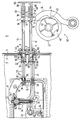
- the single figure shows a section of a door 1 with the outer door removed and a longitudinal section through the adjacent area of a container 5 and the area of a housing 6 of the dishwasher adjoining the container 5.
- an addition device 20 for powdery additive and an addition device 30 for liquid additive are arranged in a common housing.
- a common control device 40 is assigned to both addition devices 20, 30.
- the addition devices 20, 30 and the control device 40 are arranged in spatially separate, mutually movable assemblies of the household appliance, the addition devices 20, 30 in the door 1, which serves to close the container 5, and the control device 40 in the housing 6 are arranged to the container 5.
- the control device 40 consists of a program control unit, not shown, which drives a cylindrical program carrier 41 via an axis 42. On the program carrier 41 there are separate control disks for the addition devices 20 and 30 one behind the other in the axial direction arranged, only one control disk 43 for controlling the addition device 30 for liquid additives is visible in the drawing.
- a release plunger 11 with a release lever 12 connected to it is arranged in the housing 6 and a transmission tappet 21 with a rotary lever 22 connected to it in the door 1.
- a further release plunger 13 with a release lever 14 connected to it is arranged in the housing 6 and another transmission tappet 33 with a rotary lever 34 connected to it in the door.
- the trigger plungers 11 and 13 act in the operating position, i.e. with door 1 closed, on the plunger 21 and 33.
- the transmission plungers 11 and 21 and 13 and 33 are in the operating position in the region of a side wall 2 of the door 1 in front of the sealing contact of the door 1 on the container 5.
- the container 5 is bent from the plane of the drawing further back towards the door 1.
- the door 1 lies sealingly against this offset.
- the container 5 is provided with a passage opening 7, into which a plunger guide 8 is inserted, which has a guide opening 9 for the trigger plungers 11 and 13.
- the side wall 2 of the door 1 has two through openings 3 and 4 for the transmission plunger 33 and 21.
- a guide 50 with two guide parts 51 and 52 which protrude through the passage opening 3, 4 and through which the transmission plungers 21, 33 pass.
- the guide 50 has one in the door gap between the side wall 2 and the container 5 at a distance in front of the side wall 2 protruding edge 53, over which an elastic cover 60 is slipped, the clamping edge 61 is clamped between the edge 53 of the guide 50 and the outer surface of the side wall 2.
- Spring tongues 54 abutting against the inner wall of the side wall 2 serve as a counter-holder, which are deformed when the guide 5 is fitted when it is pushed through from the outer wall of the side wall 2 in the direction of the guide parts 51 and 52 and snap back outwards after being pushed in completely.
- the guide 50 is thus firmly attached to the side wall 2 of the door by means of the clamping edge 61 on the one hand and the spring tongues 54 on the other hand.
- the tappet guide 8 is screwed in a manner not shown to a housing part, also not shown.
- the transmission plungers 21 and 33 are each provided with a collar 25, 35 which can run up on end faces 55 of protruding stops 57 of the guide 50.
- the transfer plungers 21, 33 are equipped with laterally projecting lugs 26, 36 which can run onto the rear sides 56 of the projecting stops 57 of the guide 50.
- the transfer plungers 21 and 33, as well as the release plungers 11 and 13, have for the most part a cross-shaped cross section.
- the protruding stops 57 of the guide 50 are arranged in pairs at a distance which corresponds to the thickness of the cross ribs of the transmission plungers 21, 33, respectively to the right and left of the vertical cross ribs of the transmission plungers 21, 32.
- the trigger plungers 11, 13 are each provided with a constriction 15, 17 in the area of the control disk, by means of which the trigger plungers 11 and 13 are inserted into one in the exemplary embodiment, horizontal groove 16, 18 of the release lever 12, 14 are suspended.
- a collar 17 and a pin 18 are arranged on the release levers 11, 13 at the end opposite the through opening 7.
- the collar 17 of the trigger plunger for the addition device 20 for powdery addition means serves to apply a release spring 48.
- a release spring 58 rests on the collar 17 of the release tappet 13 for the addition 30 for liquid addition means.
- the trigger springs 48, 58 act in the exemplary embodiment shown between the collars 17 of the trigger plunger 11, 13 and a holder 65 fastened to the housing and thus tension the trigger plunger 11, 13 in the direction of the passage opening 7 and at the same time the trigger lever 12, 14 in the direction of the Control disc 43 before.
- the trigger springs 48, 58 are guided on the one hand on the pin 18 of the trigger plunger 11, 13 and on the other hand on the pin 66 connected to the holder 65.
- the transmission plungers 21, 33 are biased by means of return springs 28, 38 in the direction of the passage opening 3, 4.
- the return springs 28, 38 act between on the common Housing of the addition devices 20, 30 attached U-shaped receiving pockets and the transmission plungers 21, 33.
- the transmission plunger 21 has, as an attachment for the return spring 28, a rib, not shown, projecting downwards with a pin.
- the transmission plunger 33 is equipped at the end opposite the through opening 3 with a collar 37 for the abutment of the return spring 38 and with a pin 39 for guiding the return spring 38.
- An offset 34 'of a rotary lever 34 is arranged between the return spring 38 and the collar 37. The connection between the transmission plunger 33 and the rotary lever 34 is thus established.
- a continuous groove 34 ′′ is arranged, which is used to hang in a release pin 32.
- a closing body 31 made of flexible material is pushed over the release pin 32 and, with its conical end 31 'in the rest position, closes an outlet opening 70 of the addition device 30.
- a pivot pin 19 arranged on the common housing of the addition devices 20, 30 serves as the fulcrum for the rotary lever 34.
- the transmission plunger 21 is connected at its end opposite the closing spring 28 to the addition device 20 for powdery addition means by means of a rotary lever 22 attached to the transmission plunger 21 by means of a snap connection 23, which, via a pawl 24 in the rest position, a biased flap, not shown, sealing a container closes.
- the guide, not shown, in the housing for the pawl 24 serves as a fulcrum for the rotary lever 22.
- the force of the release springs 48, 58 is greater than the force of the return springs 28, 38.
- the program carrier 41 is rotated by a program control device (not shown) in the direction of the control lug 44 resiliently attached to the control disk 43 until the control lug 44 engages in the cutout 45 due to the pretensioning by the release spring 58.
- the trigger plunger 13 is advanced through the passage opening 7 in the direction of the door until it strikes the transmission plunger 33.
- the transfer plunger 33 is pressed in by the release plunger 13 in the direction of the liquid addition means 30, whereby the rotary lever 34 rotates clockwise about its pivot point 19, so that the suspended release pin 32 is raised becomes.
- the closing body 31 is also lifted out of its sealing position at the outlet opening 70 of the addition device 30.
- the now relieved transmission plunger 33 is due to the force of the return spring 38 in the direction of the side wall 2 of the door 1 up to the stop of the collar 35 on the end face 55 of the stops 57 of the guide 50 moves.
- the rotary lever 34 is rotated counterclockwise and moves the release pin 32 and thus the closing body 31 into the closed position, as a result of which the outlet opening 70 of the addition device 30 for liquid addition agent is closed.
- the movement sequence for actuation of the addition device 20 for powdery addition means takes place.
- the release lever 12 and the release plunger 11 are advanced toward the door 1 to such an extent that the transfer plunger 21 is pressed in against the force of the return spring 28 due to the force of the release spring 48.
- the rotary lever 22 is moved counterclockwise, whereby the pawl 24 is rotated, which leads to the opening of the flap of the addition device 20 for powdery additive.
- the elastic cover 60 acts as a run-on bevel because it is bent by the still protruding tappet 11, 13 in the direction of the transfer tappets 21, 33, due to the fact that the flexible cover 60 rests on the transfer tappets 21, 33. 33 which are pushed back into their release state.
- the transmission tappets 21, 33 are provided at their end opposite the release tappets 11, 13 with a bearing surface which is substantially larger than the cross section of the release tappets 11, 13.
- the above-described device for actuating the addition devices 20, 30 for additives is arranged in a simple manner in a space-saving manner in the dishwasher.
Landscapes
- Washing And Drying Of Tableware (AREA)
- Cookers (AREA)
- Selective Calling Equipment (AREA)
- Detergent Compositions (AREA)
Applications Claiming Priority (2)
| Application Number | Priority Date | Filing Date | Title |
|---|---|---|---|
| DE4041327 | 1990-12-21 | ||
| DE4041327A DE4041327C1 (OSRAM) | 1990-12-21 | 1990-12-21 |
Publications (2)
| Publication Number | Publication Date |
|---|---|
| EP0492089A1 EP0492089A1 (de) | 1992-07-01 |
| EP0492089B1 true EP0492089B1 (de) | 1994-09-14 |
Family
ID=6421122
Family Applications (1)
| Application Number | Title | Priority Date | Filing Date |
|---|---|---|---|
| EP91118622A Expired - Lifetime EP0492089B1 (de) | 1990-12-21 | 1991-10-31 | Zugabevorrichtung mit Steuereinrichtung in Haushaltgeräten |
Country Status (5)
| Country | Link |
|---|---|
| EP (1) | EP0492089B1 (OSRAM) |
| AT (1) | ATE111324T1 (OSRAM) |
| DE (3) | DE4041327C1 (OSRAM) |
| DK (1) | DK0492089T3 (OSRAM) |
| ES (1) | ES2061147T3 (OSRAM) |
Families Citing this family (4)
| Publication number | Priority date | Publication date | Assignee | Title |
|---|---|---|---|---|
| DE4219620A1 (de) * | 1992-06-16 | 1993-12-23 | Licentia Gmbh | Verfahren zur Reinigungsmittelzugabe bei Haushalt-Geschirrspülmaschinen |
| US7754025B1 (en) | 2000-06-08 | 2010-07-13 | Beverage Works, Inc. | Dishwasher having a door supply housing which holds dish washing supply for multiple wash cycles |
| US6799085B1 (en) | 2000-06-08 | 2004-09-28 | Beverage Works, Inc. | Appliance supply distribution, dispensing and use system method |
| US7083071B1 (en) | 2000-06-08 | 2006-08-01 | Beverage Works, Inc. | Drink supply canister for beverage dispensing apparatus |
Family Cites Families (3)
| Publication number | Priority date | Publication date | Assignee | Title |
|---|---|---|---|---|
| DE7536385U (de) * | 1975-11-15 | 1976-03-25 | Licentia Patent-Verwaltungs-Gmbh, 6000 Frankfurt | Geschirrspülmaschine |
| DE3442194A1 (de) * | 1984-11-17 | 1986-05-28 | Miele & Cie GmbH & Co, 4830 Gütersloh | Geschirrspuelmaschine mit einer dosiervorrichtung |
| DE3802210C2 (de) * | 1988-01-26 | 1996-03-28 | Bosch Siemens Hausgeraete | Vorrichtung zur Betätigung mindestens einer Zugabevorrichtung für Zusatzmittel in Haushaltsgeräten, insbesondere Wasch- und Geschirrspülmaschinen |
-
1990
- 1990-12-21 DE DE4041327A patent/DE4041327C1/de not_active Expired - Lifetime
-
1991
- 1991-10-31 EP EP91118622A patent/EP0492089B1/de not_active Expired - Lifetime
- 1991-10-31 DK DK91118622.9T patent/DK0492089T3/da active
- 1991-10-31 AT AT91118622T patent/ATE111324T1/de not_active IP Right Cessation
- 1991-10-31 ES ES91118622T patent/ES2061147T3/es not_active Expired - Lifetime
- 1991-10-31 DE DE59102937T patent/DE59102937D1/de not_active Expired - Lifetime
-
1992
- 1992-05-05 DE DE4214864A patent/DE4214864A1/de not_active Withdrawn
Also Published As
| Publication number | Publication date |
|---|---|
| ATE111324T1 (de) | 1994-09-15 |
| DE4214864A1 (de) | 1993-11-11 |
| DE4041327C1 (OSRAM) | 1992-06-11 |
| EP0492089A1 (de) | 1992-07-01 |
| DK0492089T3 (da) | 1995-01-02 |
| ES2061147T3 (es) | 1994-12-01 |
| DE59102937D1 (de) | 1994-10-20 |
Similar Documents
| Publication | Publication Date | Title |
|---|---|---|
| DE2243639C3 (de) | Schieberschalter | |
| DE2335972A1 (de) | Schalter, insbesondere fuer ein elektrisches handwerkzeug | |
| DE19859454A1 (de) | Verriegelungs- und Entriegelungsvorrichtung für die Türe oder Klappe eines elektrischen Haushaltsgeräts | |
| DE10209573A1 (de) | Treibstangenverschluss für eine Schiebetür | |
| DE3544667A1 (de) | Einschubrahmen mit einer schutzplatte fuer eine trennkontaktanordnung | |
| EP2276048B1 (de) | Schaltvorrichtung mit Drehgriff | |
| EP0492089B1 (de) | Zugabevorrichtung mit Steuereinrichtung in Haushaltgeräten | |
| EP0840336A2 (de) | Selbstjustierender Stösselschalter, insbesondere KFZ-Bremslichtschalter | |
| EP0937323A1 (de) | Einschiebbarer geräteträger mit einer verriegelungseinrichtung | |
| EP2289387B1 (de) | Geschirrspülmaschine, insbesondere Haushaltsgeschirrspülmaschine | |
| DE2556520C2 (de) | Verriegelungsvorrichtung | |
| DE2928194C2 (de) | Weichenantrieb | |
| DE3304037C2 (OSRAM) | ||
| DE202018103473U1 (de) | Verdampfer und elektronische Zigarette mit einem solchen Verdampfer | |
| WO2008067937A1 (de) | Schaltvorrichtung | |
| DE102022116078A1 (de) | Mechanismus für eine Tür eines elektrischen Haushaltsgeräts | |
| DE1911104C3 (de) | Elektrischer Schnappschalter | |
| DE3325531C2 (OSRAM) | ||
| DE2826712A1 (de) | Aufreissverschluss fuer die tuer von haushaltgeraeten | |
| DE3802210C2 (de) | Vorrichtung zur Betätigung mindestens einer Zugabevorrichtung für Zusatzmittel in Haushaltsgeräten, insbesondere Wasch- und Geschirrspülmaschinen | |
| DE9219023U1 (de) | Vorrichtung zur Betätigung mindestens einer Zugabevorrichtung für Zusatzmittel in Haushaltgeräten | |
| DE102015016258B4 (de) | Verriegelungsmechanik nach einem Push-Push-System | |
| WO2004017787A1 (de) | Reinigungsvorrichtung für den scherkopf eines trockenrasierapparates | |
| DE2147463B2 (de) | Eingabevorrichtung fuer pulverfoermiges waschmittel, insbesondere bei geschirrspuelmaschinen | |
| DE8810408U1 (de) | Drucktastenschalter |
Legal Events
| Date | Code | Title | Description |
|---|---|---|---|
| PUAI | Public reference made under article 153(3) epc to a published international application that has entered the european phase |
Free format text: ORIGINAL CODE: 0009012 |
|
| AK | Designated contracting states |
Kind code of ref document: A1 Designated state(s): AT BE CH DE DK ES FR GB GR IT LI LU NL SE |
|
| 17P | Request for examination filed |
Effective date: 19921216 |
|
| RAP3 | Party data changed (applicant data changed or rights of an application transferred) |
Owner name: BOSCH-SIEMENS HAUSGERAETE GMBH |
|
| 17Q | First examination report despatched |
Effective date: 19940304 |
|
| GRAA | (expected) grant |
Free format text: ORIGINAL CODE: 0009210 |
|
| AK | Designated contracting states |
Kind code of ref document: B1 Designated state(s): AT BE CH DE DK ES FR GB GR IT LI LU NL SE |
|
| REF | Corresponds to: |
Ref document number: 111324 Country of ref document: AT Date of ref document: 19940915 Kind code of ref document: T |
|
| ET | Fr: translation filed | ||
| GBT | Gb: translation of ep patent filed (gb section 77(6)(a)/1977) |
Effective date: 19940921 |
|
| REF | Corresponds to: |
Ref document number: 59102937 Country of ref document: DE Date of ref document: 19941020 |
|
| REG | Reference to a national code |
Ref country code: ES Ref legal event code: FG2A Ref document number: 2061147 Country of ref document: ES Kind code of ref document: T3 |
|
| ITF | It: translation for a ep patent filed | ||
| REG | Reference to a national code |
Ref country code: GR Ref legal event code: FG4A Free format text: 3013820 |
|
| REG | Reference to a national code |
Ref country code: DK Ref legal event code: T3 |
|
| EAL | Se: european patent in force in sweden |
Ref document number: 91118622.9 |
|
| PLBE | No opposition filed within time limit |
Free format text: ORIGINAL CODE: 0009261 |
|
| STAA | Information on the status of an ep patent application or granted ep patent |
Free format text: STATUS: NO OPPOSITION FILED WITHIN TIME LIMIT |
|
| 26N | No opposition filed | ||
| PGFP | Annual fee paid to national office [announced via postgrant information from national office to epo] |
Ref country code: DK Payment date: 19980921 Year of fee payment: 8 |
|
| PGFP | Annual fee paid to national office [announced via postgrant information from national office to epo] |
Ref country code: LU Payment date: 19981016 Year of fee payment: 8 |
|
| PGFP | Annual fee paid to national office [announced via postgrant information from national office to epo] |
Ref country code: BE Payment date: 19981021 Year of fee payment: 8 |
|
| REG | Reference to a national code |
Ref country code: CH Ref legal event code: NV Representative=s name: ISLER & PEDRAZZINI AG |
|
| PGFP | Annual fee paid to national office [announced via postgrant information from national office to epo] |
Ref country code: NL Payment date: 19981031 Year of fee payment: 8 |
|
| PG25 | Lapsed in a contracting state [announced via postgrant information from national office to epo] |
Ref country code: DK Free format text: LAPSE BECAUSE OF NON-PAYMENT OF DUE FEES Effective date: 19991031 Ref country code: LU Free format text: LAPSE BECAUSE OF NON-PAYMENT OF DUE FEES Effective date: 19991031 Ref country code: BE Free format text: LAPSE BECAUSE OF NON-PAYMENT OF DUE FEES Effective date: 19991031 |
|
| BERE | Be: lapsed |
Owner name: BOSCH-SIEMENS HAUSGERATE G.M.B.H. Effective date: 19991031 |
|
| PG25 | Lapsed in a contracting state [announced via postgrant information from national office to epo] |
Ref country code: NL Free format text: LAPSE BECAUSE OF NON-PAYMENT OF DUE FEES Effective date: 20000501 |
|
| NLV4 | Nl: lapsed or anulled due to non-payment of the annual fee |
Effective date: 20000501 |
|
| REG | Reference to a national code |
Ref country code: DK Ref legal event code: EBP |
|
| PGFP | Annual fee paid to national office [announced via postgrant information from national office to epo] |
Ref country code: AT Payment date: 20000922 Year of fee payment: 10 |
|
| PGFP | Annual fee paid to national office [announced via postgrant information from national office to epo] |
Ref country code: GB Payment date: 20001027 Year of fee payment: 10 |
|
| PGFP | Annual fee paid to national office [announced via postgrant information from national office to epo] |
Ref country code: CH Payment date: 20011019 Year of fee payment: 11 |
|
| PG25 | Lapsed in a contracting state [announced via postgrant information from national office to epo] |
Ref country code: AT Free format text: LAPSE BECAUSE OF NON-PAYMENT OF DUE FEES Effective date: 20011031 Ref country code: GB Free format text: LAPSE BECAUSE OF NON-PAYMENT OF DUE FEES Effective date: 20011031 |
|
| REG | Reference to a national code |
Ref country code: GB Ref legal event code: IF02 |
|
| GBPC | Gb: european patent ceased through non-payment of renewal fee |
Effective date: 20011031 |
|
| PG25 | Lapsed in a contracting state [announced via postgrant information from national office to epo] |
Ref country code: LI Free format text: LAPSE BECAUSE OF NON-PAYMENT OF DUE FEES Effective date: 20021031 Ref country code: CH Free format text: LAPSE BECAUSE OF NON-PAYMENT OF DUE FEES Effective date: 20021031 |
|
| REG | Reference to a national code |
Ref country code: CH Ref legal event code: PL |
|
| PGFP | Annual fee paid to national office [announced via postgrant information from national office to epo] |
Ref country code: FR Payment date: 20051019 Year of fee payment: 15 |
|
| PGFP | Annual fee paid to national office [announced via postgrant information from national office to epo] |
Ref country code: GR Payment date: 20051024 Year of fee payment: 15 Ref country code: SE Payment date: 20051024 Year of fee payment: 15 |
|
| PGFP | Annual fee paid to national office [announced via postgrant information from national office to epo] |
Ref country code: IT Payment date: 20061031 Year of fee payment: 16 |
|
| PG25 | Lapsed in a contracting state [announced via postgrant information from national office to epo] |
Ref country code: SE Free format text: LAPSE BECAUSE OF NON-PAYMENT OF DUE FEES Effective date: 20061101 |
|
| EUG | Se: european patent has lapsed | ||
| REG | Reference to a national code |
Ref country code: FR Ref legal event code: ST Effective date: 20070629 |
|
| PG25 | Lapsed in a contracting state [announced via postgrant information from national office to epo] |
Ref country code: FR Free format text: LAPSE BECAUSE OF NON-PAYMENT OF DUE FEES Effective date: 20061031 |
|
| PG25 | Lapsed in a contracting state [announced via postgrant information from national office to epo] |
Ref country code: GR Free format text: LAPSE BECAUSE OF NON-PAYMENT OF DUE FEES Effective date: 20070503 |
|
| PG25 | Lapsed in a contracting state [announced via postgrant information from national office to epo] |
Ref country code: IT Free format text: LAPSE BECAUSE OF NON-PAYMENT OF DUE FEES Effective date: 20071031 |
|
| PGFP | Annual fee paid to national office [announced via postgrant information from national office to epo] |
Ref country code: DE Payment date: 20101031 Year of fee payment: 20 |
|
| PGFP | Annual fee paid to national office [announced via postgrant information from national office to epo] |
Ref country code: ES Payment date: 20101021 Year of fee payment: 20 |
|
| REG | Reference to a national code |
Ref country code: DE Ref legal event code: R071 Ref document number: 59102937 Country of ref document: DE |
|
| REG | Reference to a national code |
Ref country code: DE Ref legal event code: R071 Ref document number: 59102937 Country of ref document: DE |
|
| REG | Reference to a national code |
Ref country code: ES Ref legal event code: FD2A Effective date: 20120220 |
|
| PG25 | Lapsed in a contracting state [announced via postgrant information from national office to epo] |
Ref country code: ES Free format text: LAPSE BECAUSE OF EXPIRATION OF PROTECTION Effective date: 20111101 |
|
| PG25 | Lapsed in a contracting state [announced via postgrant information from national office to epo] |
Ref country code: DE Free format text: LAPSE BECAUSE OF EXPIRATION OF PROTECTION Effective date: 20111101 |