EP0488378B1 - Kniegelenkendoprothese - Google Patents
Kniegelenkendoprothese Download PDFInfo
- Publication number
- EP0488378B1 EP0488378B1 EP91120536A EP91120536A EP0488378B1 EP 0488378 B1 EP0488378 B1 EP 0488378B1 EP 91120536 A EP91120536 A EP 91120536A EP 91120536 A EP91120536 A EP 91120536A EP 0488378 B1 EP0488378 B1 EP 0488378B1
- Authority
- EP
- European Patent Office
- Prior art keywords
- knee joint
- plane
- joint endoprosthesis
- endoprosthesis according
- tibia
- Prior art date
- Legal status (The legal status is an assumption and is not a legal conclusion. Google has not performed a legal analysis and makes no representation as to the accuracy of the status listed.)
- Expired - Lifetime
Links
- 210000003127 knee Anatomy 0.000 title description 3
- 210000002303 tibia Anatomy 0.000 claims description 89
- 210000000629 knee joint Anatomy 0.000 claims description 69
- 210000000689 upper leg Anatomy 0.000 claims description 66
- 210000001699 lower leg Anatomy 0.000 claims description 33
- 238000005452 bending Methods 0.000 claims description 19
- 238000003780 insertion Methods 0.000 claims description 12
- 230000037431 insertion Effects 0.000 claims description 12
- 238000006073 displacement reaction Methods 0.000 claims description 8
- 239000000463 material Substances 0.000 claims description 8
- 210000002414 leg Anatomy 0.000 claims description 5
- 229920003023 plastic Polymers 0.000 claims description 2
- 239000004033 plastic Substances 0.000 claims description 2
- 210000003414 extremity Anatomy 0.000 claims 11
- 230000000630 rising effect Effects 0.000 claims 1
- 210000000988 bone and bone Anatomy 0.000 description 21
- 238000002271 resection Methods 0.000 description 6
- 239000002184 metal Substances 0.000 description 5
- 210000004417 patella Anatomy 0.000 description 5
- 239000004698 Polyethylene Substances 0.000 description 4
- 230000002349 favourable effect Effects 0.000 description 4
- -1 polyethylene Polymers 0.000 description 4
- 229920000573 polyethylene Polymers 0.000 description 4
- 210000004872 soft tissue Anatomy 0.000 description 4
- 238000004873 anchoring Methods 0.000 description 2
- 230000015572 biosynthetic process Effects 0.000 description 2
- 230000006735 deficit Effects 0.000 description 2
- 230000000694 effects Effects 0.000 description 2
- 238000002513 implantation Methods 0.000 description 2
- 230000006641 stabilisation Effects 0.000 description 2
- 238000011105 stabilization Methods 0.000 description 2
- 210000001519 tissue Anatomy 0.000 description 2
- 238000012546 transfer Methods 0.000 description 2
- 240000003517 Elaeocarpus dentatus Species 0.000 description 1
- 206010023204 Joint dislocation Diseases 0.000 description 1
- 241001227561 Valgus Species 0.000 description 1
- 238000010521 absorption reaction Methods 0.000 description 1
- 230000004308 accommodation Effects 0.000 description 1
- 210000003484 anatomy Anatomy 0.000 description 1
- 230000005540 biological transmission Effects 0.000 description 1
- 239000002639 bone cement Substances 0.000 description 1
- 230000037118 bone strength Effects 0.000 description 1
- 238000010276 construction Methods 0.000 description 1
- 238000013461 design Methods 0.000 description 1
- 238000003745 diagnosis Methods 0.000 description 1
- 238000005553 drilling Methods 0.000 description 1
- 210000000501 femur body Anatomy 0.000 description 1
- 239000007943 implant Substances 0.000 description 1
- 238000012423 maintenance Methods 0.000 description 1
- 238000005096 rolling process Methods 0.000 description 1
- 230000000087 stabilizing effect Effects 0.000 description 1
- 238000001356 surgical procedure Methods 0.000 description 1
- 210000001694 thigh bone Anatomy 0.000 description 1
- 238000012549 training Methods 0.000 description 1
- 238000011144 upstream manufacturing Methods 0.000 description 1
Images

Classifications
-
- A—HUMAN NECESSITIES
- A61—MEDICAL OR VETERINARY SCIENCE; HYGIENE
- A61B—DIAGNOSIS; SURGERY; IDENTIFICATION
- A61B17/00—Surgical instruments, devices or methods
- A61B17/16—Instruments for performing osteoclasis; Drills or chisels for bones; Trepans
- A61B17/17—Guides or aligning means for drills, mills, pins or wires
- A61B17/1739—Guides or aligning means for drills, mills, pins or wires specially adapted for particular parts of the body
- A61B17/1764—Guides or aligning means for drills, mills, pins or wires specially adapted for particular parts of the body for the knee
-
- A—HUMAN NECESSITIES
- A61—MEDICAL OR VETERINARY SCIENCE; HYGIENE
- A61F—FILTERS IMPLANTABLE INTO BLOOD VESSELS; PROSTHESES; DEVICES PROVIDING PATENCY TO, OR PREVENTING COLLAPSING OF, TUBULAR STRUCTURES OF THE BODY, e.g. STENTS; ORTHOPAEDIC, NURSING OR CONTRACEPTIVE DEVICES; FOMENTATION; TREATMENT OR PROTECTION OF EYES OR EARS; BANDAGES, DRESSINGS OR ABSORBENT PADS; FIRST-AID KITS
- A61F2/00—Filters implantable into blood vessels; Prostheses, i.e. artificial substitutes or replacements for parts of the body; Appliances for connecting them with the body; Devices providing patency to, or preventing collapsing of, tubular structures of the body, e.g. stents
- A61F2/02—Prostheses implantable into the body
- A61F2/30—Joints
- A61F2/38—Joints for elbows or knees
- A61F2/3836—Special connection between upper and lower leg, e.g. constrained
- A61F2/384—Special connection between upper and lower leg, e.g. constrained hinged, i.e. with transverse axle restricting the movement
- A61F2/385—Special connection between upper and lower leg, e.g. constrained hinged, i.e. with transverse axle restricting the movement also provided with condylar bearing surfaces
-
- A—HUMAN NECESSITIES
- A61—MEDICAL OR VETERINARY SCIENCE; HYGIENE
- A61B—DIAGNOSIS; SURGERY; IDENTIFICATION
- A61B17/00—Surgical instruments, devices or methods
- A61B17/14—Surgical saws
- A61B17/15—Guides therefor
- A61B17/154—Guides therefor for preparing bone for knee prosthesis
- A61B17/155—Cutting femur
-
- A—HUMAN NECESSITIES
- A61—MEDICAL OR VETERINARY SCIENCE; HYGIENE
- A61F—FILTERS IMPLANTABLE INTO BLOOD VESSELS; PROSTHESES; DEVICES PROVIDING PATENCY TO, OR PREVENTING COLLAPSING OF, TUBULAR STRUCTURES OF THE BODY, e.g. STENTS; ORTHOPAEDIC, NURSING OR CONTRACEPTIVE DEVICES; FOMENTATION; TREATMENT OR PROTECTION OF EYES OR EARS; BANDAGES, DRESSINGS OR ABSORBENT PADS; FIRST-AID KITS
- A61F2/00—Filters implantable into blood vessels; Prostheses, i.e. artificial substitutes or replacements for parts of the body; Appliances for connecting them with the body; Devices providing patency to, or preventing collapsing of, tubular structures of the body, e.g. stents
- A61F2/02—Prostheses implantable into the body
- A61F2/30—Joints
- A61F2/38—Joints for elbows or knees
- A61F2/3836—Special connection between upper and lower leg, e.g. constrained
- A61F2/384—Special connection between upper and lower leg, e.g. constrained hinged, i.e. with transverse axle restricting the movement
- A61F2/3845—Special connection between upper and lower leg, e.g. constrained hinged, i.e. with transverse axle restricting the movement allowing only for single rotation
Definitions
- the invention relates to a knee joint endoprosthesis with a Femoral part and a tibial part, which one around them together connecting hinge joint, the pivot axis of a unchangeable distance from both the femur part and from the tibia part, from an extended position in an angled position pivotable in a bending plane are stored and each have shanks that are angled Include a flexion angle between them and in an extended position in each other point in opposite directions, with the femoral part facing it has attached arched wings and through the shafts each have a longitudinal axis that extends in a straight line Position essentially in transverse to the flexion plane arranged mutually plane-parallel shaft planes are, of the shaft planes that of the femoral part a larger horizontal distance from a plane parallel to them through the swivel axis vertical plane in Direction towards a rear enclosed by the bending angle Part of the femoral part adheres to as the shaft plane of the Tibial part and between the shaft plane of the
- Such knee joint endoprostheses are hinge joints known in the professional world and become successful in particular then implanted if it turns out that one too treating patients the soft tissue apparatus surrounding the knee joint is no longer strong enough to meet the Femur part with the necessary force in the operative context with to hold the tibia part.
- the replacement of the knee joint with an endoprosthesis has shown that it is not possible to use a flexion movement of the two hinge parts enabling the hinge enabled by constructive measures will, longitudinal movements either towards a femur or a lower leg bone and the stability of the entire endoprosthesis is thereby achieved is that the two prosthesis parts form-fitting each other act upon.
- Damage to the soft tissue covering leads to this for the stabilization of a such a system is insufficient to withstand material loads System or luxations due to displacements of the joint to prevent those with significant pain for the patient are connected and lead to the dislocated endoprosthesis becomes inoperable.
- hinge prostheses of the type mentioned in the introduction pose only a low risk, because the distance between them, which is constructive between the Hinge joint on the one hand and the femur part or the tibia part on the other hand, cannot change.
- Form closure brings increased stability to the endoprosthesis and involves only a low risk for Material damage.
- the hinge joint therefore ensures that the femoral part with the tibia part is always in a predetermined Operating position interact. Movements of the Femoral part with respect to the tibia part or with respect to the tibia part of the femur part in the longitudinal direction of neither the lower leg nor the thigh bone are possible.
- this fixed assignment of the tibia part causes on the one hand and the femoral part on the other hand with regard to its position immovable hinge joint that all swivel movements can only take place around the immovable with respect to the two joint parts and in its position precisely defined central axis of the swivel joint.
- This central axis can therefore change Do not adapt the stress conditions and positions of the knee joint.
- such a hinge joint carries the one natural movements of the knee are not sufficient Bill, but makes a compromise in terms the desired operational safety and the achievable Sequence of movements.
- a knee joint endoprosthesis is known from DE-A-212 23 90, which is designed as a hinge joint, in which a Femur part pivotable about a shaft about its pivot axis is connected to a tibia part. Run through the shafts Longitudinal axes, which in the extended position essentially in plane-parallel parallel to the flexion plane Shaft planes are arranged.
- the shaft plane of the femoral shaft is anterior to the shaft plane of the tibia shaft upstream.
- the shaft level of the tibia shaft falls approximately with a vertical axis running through the swivel axis together.
- Arc-shaped are firmly connected to the femoral part Wings are provided in the tibial slide can slide.
- a horizontal shift plane runs tangential to a support surface formed on the tibia part at a vertical distance from one through the Horizontal plane.
- the object of the present invention is therefore a Knee joint endoprosthesis of the type mentioned in the introduction improve that the pivoting movements that can be carried out with their help largely the pivoting movements of a natural Knee joint are adjusted.
- the Horizontal distance between the shaft plane of the femur part and the vertical plane is 16 to 21 mm that the Distance between the shaft plane of the tibia part and the shaft plane of the femur part is small with 0.5 to 4 mm compared to the horizontal distances between the vertical plane and the respective shaft planes that the vertical distance Is 20 to 24 mm, and that with even loading of the two parts the arcuate attached to the femoral part Glide wings on the contact surface, which at one-sided loading of one of the two wings on the the loaded Wing opposite surface under pressure are.
- the knee joint prosthesis is based on the three described Parameters designed so that they are the essential natural movements that take place in a knee joint, can largely simulate. This way it is ensured that both the femur part and the tibia part on Permanently attached to the bones next to them are and cannot loosen easily. Through the the forces are easily introduced into the bones Low stress on the respective bones.
- the level of the shaft becomes the pivotability of the tibia part favorably influenced compared to the femur part to others are in the extended position of the Endoprosthesis essentially in a stress level that leads to a favorable transfer of forces and one Particularly great stability when the endoprosthesis is stretched having. These advantages are particularly favorable if the shaft distance is between 1.5 and 2.5 mm.
- the horizontal distance about 16 mm and the vertical distance about 23 mm. This will make a good compromise between the desired tissue relief and the required at the same time Maintenance of bone stability closed. Larger horizontal distances lead to poor implantation conditions and high loads in the patella joint. If the horizontal distance is reduced, one is larger bone resection for the purpose of anchoring the endoprosthesis required. Because of the invention Arrangement of the pivot axis can both relieve tissue as well as maintaining bone strength be guaranteed. Those for the femoral and tibial Partly chosen respective horizontal distances lead in comparison to other systems to a significant pressure relief of the patella joint because there is no feed in the area the thigh roll can occur.
- This feed in the area of the thigh roll represents a completely unphysiological Stress on the endoprosthesis joint.
- This pressure relief of the patella joint is special important because the patella joint is natural Usually function without joint replacement becomes. By maintaining the natural patella joint there is a considerable saving in resection, so that the knee joint can only be used in special situations is replaced, mainly for corrective surgery.
- the housing facing away from the housing interior Outer walls of its lateral boundaries each a grand piano, each of which is in one from the interior of the cabinet points in the opposite direction and forms an arc on one extends lower edge of the housing, the tibia part is facing towards the wing one Have sliding surface.
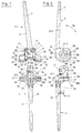
- a knee joint prosthesis essentially consists of one Tibial part (1) and a femoral part (2).
- the tibia part (1) has a tibia shaft (3), the femoral part (2) one Femoral shaft (4).
- the two shafts (3, 4) point in directions facing away from each other and are used for attachment of the parts (1, 2) in a bone adjacent to them.
- Femur part (2) is a housing (6) guiding a shaft (5) arranged.
- This shaft is fixed in the tibia part (1) and rotatably supported in the femoral part (2).
- Rotational movements of the shaft (5) guide the two parts (1, 2) Swiveling movements in a bending plane (96) against each other out.
- each of the two shafts (3, 4) a shaft plane running perpendicular to the flexion plane (96) (97, 123) extends into a pivoted position (110), in which a longitudinal axis of the femur extending through the femoral shaft (4) (7) with a through the tibia shaft (3) extending tibial longitudinal axis (16) a bending angle (111) between them.
- This diffraction angle (111) encloses a rear part (112) of the femur part (2) and a rear part (113) of the tibia part (1).
- the housing In the area of its essentially plane-parallel to Bending plane (96) extending lateral boundaries (8, 9) the housing has recesses (10, 11). These recesses (10, 11) are essentially centered on one pivot axis (12) extending through the shaft (5) aligned, which is essentially transverse to the bending plane (96) extends. Extends through the pivot axis (12) a vertical plane (78) that is plane-parallel at a horizontal distance (13) to that extending through the femoral shaft (4) Shaft level (123) and at a horizontal distance (121) to that extending through the tibia shaft (3) Shaft level (97) runs.
- pivot axis (12) extends through a horizontal plane (79), a vertical distance in the direction of the tibia part (1) (15) to a horizontal shift plane (114).
- This horizontal displacement plane (114) runs tangentially to a line (115) that is perpendicular to the bending plane (96) through a part opposite the femur part (2) on the tibia part (1) trained support surface (117) extends.
- This support surface (117) is opposite in the direction of the femoral part (2) a sliding surface (14) formed which is suitable is to perform sliding movements on the contact surface (117), if the tibia part (1) about the pivot axis (12) Pivots with respect to the femur part (2).
- the tibia shaft (3) runs in the direction of a tibial longitudinal axis (16) and the femoral shaft (4) towards one Longitudinal axis of the femur (7).
- the femoral shaft has (4) in a front view running transversely to the shaft plane (123) an oblique position in relation to the tibia shaft (3). This inclination corresponds to a medium one Valgus angle.
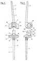
- the recesses (10, 11) serve to accommodate bearing shells (27, 28) in which the shaft (5) is mounted.
- These bearing shells (27, 28) each have a collar (23, 24) with which they protrude into the recesses (10, 11).
- Contact surfaces adjoin this collar (23, 24) (21, 22) with which the bearing shells (27, 28) in a housing interior (20) enclosed by the housing (6) protrude into it.
- These contact surfaces (21, 22) lie with their outer surfaces (18, 18) facing away from the housing interior (20) 19) on the lateral boundaries (8, 9) of the housing (6) on. In this way, the housing interior (20) is on both sides bounded by inner walls (98, 99) by the bearing shells (27, 28) are formed.
- These cups (27, 28) consist of polyethylene and therefore represent one ideal sliding partner for a web (33) with which the Tibia part (1) protrudes into the housing interior (20).
- the dimensions of the web (33) are chosen so that this with its side walls (93, 94) on the Inner walls (98, 99) is guided.
- a blind hole (29) is provided in which the shaft (5) is mounted is.
- This blind hole (29) is made by a closing one Floor (30) limits the shaft (5) in the longitudinal direction of the Swivel axis (12) leads.
- Both the through hole (31) and the blind hole (29) also has an inner diameter (32), which corresponds to an outer diameter of the shaft (5), so that the shaft (5) both in the through hole (31) as well as in the blind hole (29).
- the lateral boundaries delimiting the housing (6) (8, 9) bear on their facing away from the housing interior (20)
- Outer surfaces of wings (25, 26) which extend from the housing (6) extend in a direction facing away from the interior (20).
- These wings (25, 26) extend in an arc on one Lower edge (82) in directions pointing away from each other. This lower edge (82) faces the tibia part (1).
- the sliding surface (14) is located on one of the tibia parts (1) facing lower surface of the wing (25, 26).
- the wings (25, 26) have parallel to the direction of Swivel axis (12) a relatively large width, so that it span a wide sliding surface (14) with which they open a bearing surface (38) are guided on the tibia part (1) is arranged.
- This bearing surface (38) is a curved one Support surface (117), the curvature of which is essentially that of the wing (25, 26) is simulated.
- the Width of each of the two wings (25, 26) corresponds approximately to that half the width of the housing (6).
- the sliding surfaces (14) of the two wings (25, 26) each have one in Towards the tibia part (1) convexly weak Inclination that extends from the housing (6) towards Outer edges (80, 81) extends.
- outer edges (80, 81) limit the wings (25, 26) on the housing (6) opposite side. Configure these outer edges (80, 81) essentially with outer edges (84, 85) one Support plate (35), the tibia part (1) opposite the femoral part (2) limited. This support plate (35) clamps one Support surface running transversely to the direction of the shaft plane (97) (117).
- the wings (25, 26) extend approximately to one Swivel axis (12) concentric arc of about 180 ° along the lower edge (82) of the femur part (2).
- everyone Wing (25, 26) points towards the rear Part (112) of the femur portion end (83) which from one from the horizontal plane (79) with the lower edge (82) of the housing (6) formed section line (86) in the form of a circular arc concentric to the central axis (12) and in stretched condition of the knee joint prosthesis a little rear end lying above the horizontal plane (79) (83).
- This rear end (83) is the bearing surface (117) adjacent if the femoral part (2) opposite the Tibial part (1) is pivoted.
- Each wing (25, 26) extends along an arc (87) from the rear end (83) to an opposite end front end (88) that in a the rear part (112) of the femur part (2) opposite front end face (89) of the housing (6).
- the front end (88) is about one in the extended state of the prosthesis same distance in the direction of the tibia part (1) below the horizontal plane (79) like the rear end (83) lies above this horizontal plane (79).
- the bow (87) points from the rear end (83) to the front End (88) different radii of curvature. So he is in Area of its rear end (83) and in the area of its front end (88) curved less than in its central region (90).
- the front ends (88) of the two wings (25, 26) are facing away from the tibia part (1) via a short one arched short arch (91) interconnected, which in a front end wall (92) delimiting the housing (6) is trained.
- the web (33) has a recess (34), which as a extending essentially centrally to the pivot axis (12) Bore is formed. This serves to receive the shaft (5).
- the web (33) rises on the support plate (35), to the horizontal surface of the side walls (93, 94) run vertically.
- These side walls (93, 94) have an approximately equal distance (95) from the center through the tibia part (1) extending flexion plane (96).
- the side walls (93, 94) thus also run plane-parallel to the inner walls (98, 99) of the housing (6) to which they are led.
- the housing interior (20) has one transverse to the bending plane (96) substantially rectangular cross section.
- the interior of the housing (20) is towards the front end (88) from essentially plane-parallel to the shaft plane (123) running end surface (89) is limited while in Direction towards the rear end (83) is open.
- the web (33) rises centrally on the support plate (35). It is designed as an eyelet, the part of the femur (2) facing upper limit (100) as a concentric is rounded to the recess (34).
- the web (33) extends in the direction of the femoral part (2) through a bearing shell (37) on the platen (35) is arranged. This platen (35) is with the help supported by ribs (36) opposite the tibia shaft (3).
- the bearing shell (37) engages around the web (33) in a U-shape and extends along the side walls (93, 94) two webs (101, 102) in one of the front end surface (89) facing front part (103) of the platen (35) connected to each other by a yoke (104) are. Extends between the two webs (101, 102) an opening (105) to one of the front part (103) opposite rear part (106) of the platen (35). Raised on this rear part (106) of the support plate through the opening (105) of the web (33).
- the bearing surface (38) is formed on the bearing shell (37), which faces the sliding surface (14).
- the storage area (38) runs on a side facing the femur part (2) Surface of the webs (101, 102) from the front part (103) in Direction to the rear part (106) in which they open.
- the bearing surface (38) has one facing the yoke (104) front part (107) of the front end (88) of the Wing (25, 26) is opposite. Opposite one in the back Part of the bearing shell (37) opening flat part (108) of the bearing surface (38) is the front part (107) in Direction raised on the femoral part (2).
- the flat part (108) of the bearing surface (38) extends within the Contact surface (117). Between the bearing surface (38) and the its facing sliding surface (14) of the wings (25, 26) in the evenly loaded state of the prosthesis Sliding play. Supports the prosthesis in the event of one-sided loads the sliding surface (14) of the loaded wing (25, 26) on the bearing surface (38) and in this way prevents that the web (33) in the housing (6) when performing tilted by swivel movements.
- the bearing surface (38) points in the longitudinal direction from its flat Part (108) to its front part (107) a curvature (116) on the one facing the front part (107) Third has a relatively steep increase. About that also has the bearing surface (38) in its transverse to Longitudinal transverse direction a curvature that the curvature of the sliding surface (14) is adapted. On this in the transverse direction, the wings (25, 26) performed when performing flexion movements. This in The transverse curvature stabilizes the knee joint in the extended position in that the tibia part (2) in the front part (103) of the support plate (35) the lower edge (82) of the housing (6) leads positively.
- the bearing shell (37) is expediently made of polyethylene trained so that they are an ideal sliding partner to the Forms sliding surfaces (14) of the wings (25, 26). To this Even when the two parts (1, 2) reckon that the sliding surface (14) sliding movements can run on the bearing shell (27, 28).
- the shaft (5) is in the recess (34) with the help of a Set screw (46) attached.
- This extends through a bore (41) which extends transversely to the pivot axis (12) through the Web (33) runs in the direction of the recess (34).
- the Bore (41) corresponds to one provided in the shaft (5) Bore (44) into which the grub screw (46) protrudes, when it is screwed into the bore (41).
- the grub screw (45) is in the hole (41) screwed in until you turn away from the shaft (5) End below a surface of the web (33) inside the bore (41).
- a bore (42) can be arranged in the shaft (5) be in the direction of the pivot axis (12) extends and is provided with an internal thread (43).
- This bore (42) is used for mounting the shaft (5), if this through the through hole (31) into the blind hole (29) is fitted and then aligned the grub screw (46) through the bore (41) into the bore provided with an internal thread (45) (44) is screwed in.
- centering stars (47) can be arranged in the area of the ends of the shafts (3, 4) centering stars (47) can be arranged. But it is also possible, a centering star only in the area of one of the shafts (47) or the endoprosthesis without centering stars (47) to implant.
- the centering star (47) is formed essentially centrally to the shaft axis (17) and tapers into a shaft facing away from the shaft (3, 4) Direction.
- the centering star (47) has it stabilizing and when inserted into a bone recess centering wings (48).
- the shaft (5) is fixed in the area of the femur part (2) and the recess (34) in the web (33) with one in the direction of the femur part (2) oriented insertion opening (49).
- the insertion opening (49) enables assembly the tibia part (1) and the femur part (2) without lateral Insert the bearing pin (5). The introduction of an additional This avoids drilling into the femur will.
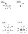
- the insertion opening (49) is like this trained that in the lateral boundaries (8, 9) attached shaft (5) with a narrow point (120) in the Insertion opening (49) can be inserted. This narrow point (120) is in the extended position of the knee joint pivoted relative to the insertion opening (49).
- the insertion opening (49) by a screw extending transversely to it to be closed, which are designed as a grub screw should.
- This bolt (124) is advantageously with a Grub screw (129) attached to the legs (125, 126).
- it is for better guidance of the bolt (124) also possible this with two springs (131, 132) in corresponding Grooves (133, 134) of the legs (125, 126).
- the bearing shells (27, 28, 37) are preferably made of one durable plastic, for example polyethylene, educated.
- the shaft (5) consists of a metal. But it is also possible to make the shaft from a metal core train from one of polyethylene, for example trained envelope is enclosed. In this case exist the bearing shells made of metal.
- the bearing shell (37) impinging wings (25, 26) are preferably made of one hard metal and their sliding surfaces (14) are polished.
- For the horizontal distance (13) is a dimension of about 16 to 21 mm provided. Particularly advantageous in With regard to a variety of applications, a horizontal distance is of 16 mm.
- the shafts (3, 4) are also made of metal and are large in relation to their diameters Longitudinal extension in the direction of the shaft axis (4, 16).
- the shafts (3, 4) are preferably free of undercuts educated.
- a flexible elastic Formation of the shafts (3, 4) can change the bending behavior of each bone can be adjusted so that reduced the risk of loosening the shafts (3, 4) becomes.
- the shafts (3, 4) have one rectangular cross-section with rounded edges. This Cross-sectional shape has proven to be particularly favorable in order to be able to absorb the forces that occur, on the other hand, also to prevent the Shafts (3, 4) under the load of torsional forces in Loosen bones. Finally, this cross-sectional shape offers a high level of security against possible notch effects.
Landscapes
- Health & Medical Sciences (AREA)
- Orthopedic Medicine & Surgery (AREA)
- Life Sciences & Earth Sciences (AREA)
- General Health & Medical Sciences (AREA)
- Surgery (AREA)
- Veterinary Medicine (AREA)
- Oral & Maxillofacial Surgery (AREA)
- Engineering & Computer Science (AREA)
- Biomedical Technology (AREA)
- Heart & Thoracic Surgery (AREA)
- Public Health (AREA)
- Animal Behavior & Ethology (AREA)
- Transplantation (AREA)
- Vascular Medicine (AREA)
- Cardiology (AREA)
- Dentistry (AREA)
- Nuclear Medicine, Radiotherapy & Molecular Imaging (AREA)
- Physical Education & Sports Medicine (AREA)
- Medical Informatics (AREA)
- Molecular Biology (AREA)
- Prostheses (AREA)
- Surgical Instruments (AREA)
Description
- Fig. 1:
- Einen Längsschnitt durch eine Endoprothese mit vom Tibiateil abgenommenen Femurteil gem. Schnittlinie I-I in Fig. 2,
- Fig. 2:
- eine Seitenansicht der Endoprothese gem. Fig. 1,
- Fig. 3:
- einen Längsschnitt durch Zwei zur Aufnahme der Welle vorgesehene Lagerschalen und eine Ansicht einer Welle mit einer Zentrierschraube,
- Fig. 4:
- eine teilweise Darstellung eines Prothesenschaftes mit Zentrierstern,
- Fig. 5:
- eine skizzenhafte Darstellung der gestreckten Endoprothese mit Achsenlagen in Relation zu den Schäften und zur Abrollfläche,
- Fig. 6:
- eine skizzenhafte Darstellung der verschwenkten Endoprothese,
- Fig. 7:
- eine Vorderansicht einer Kniegelenkendoprothese mit zusammensteckbarem Tibia- und Femurteil,
- Fig. 8:
- eine Seitenansicht der Prothese nach Fig. 7,
- Fig. 9:
- eine Seitenansicht einer Welle,
- Fig.10:
- einen Querschnitt durch eine Welle entlang der Schnittlinie XIX-XIX in Fig. 9,
- Fig.11:
- eine Seitenansicht eines anderen Führungselementes und
- Fig.12:
- eine Draufsicht auf ein anders Führungselement.
Claims (43)
- Kniegelenkendoprothese mit einem Femurteil (2) und einem Tibiateil (1), die um ein sie miteinander verbindendes Scharniergelenk, dessen Schwenkachse (12) einen nicht veränderbaren Abstand sowohl vom Femurteil (2) als auch vom Tibiateil (1) besitzt, von einer gestreckten Stellung in eine abgewinkelte Stellung in einer Beugeebene (96) verschwenkbar gelagert sind und jeweils Schäfte (3, 4) aufweisen, die in abgewinkelter Stellung einen Beugewinkel (11) zwischen sich einschließen und in gestreckter Stellung in einander entgegengesetzte Richtungen weisen, wobei das Femurteil (2) an ihm befestigte bogenförmige Flügel (25, 26) aufweist und sich durch die Schäfte (3, 4) jeweils eine Längsachse (7, 16) erstreckt, die in gestreckter Stellung im wesentlichen in quer zur Beugeebene (96) verlaufenden einander planparallelen Schaftebenen (97, 123) angeordnet sind, wobei von den Schaftebenen (97, 123) die des Femurteils (2) einen größeren Horizontalabstand (13) von einer planparallel zu ihnen durch die Schwenkachse (12) verlaufende Vertikalebene (78) in Richtung auf einen vom Beugewinkel (111) eingeschlossenen hinteren Teil (112) des Femurteils (2) einhält als die Schaftebene (97) des Tibiateils (1)und wobei zwischen der Schaftebene (97) des Tibiateils (1) und der Schaftebene (123) des Femurteils (2) ein Schaftabstand (122) besteht und eine senkrecht zur Vertikalebene (78) durch die Schwenkachse (12) verlaufende Horizontalebene (79) in Richtung auf den Tibiateil (1) einen Vertikalabstand (15) zu einer horizontalen Verschiebeebene (114), die sich tangential zu einer auf dem Tibiateil (1) ausgebildeten Auflagefläche (117) erstreckt, einhält, dadurch gekennzeichnet, daß der Horizontalabstand (13) zwischen der Schaftebene (123) des Femurteils (2) und der Vertikalebene (78) 16 bis 21 mm beträgt, daß der Schaftabstand (122) zwischen der Schaftebene (97) des Tibiateils (1) und der Schaftebene (123) des Femurteiles (2) mit 0,5 bis 4 mm klein ist verglichen mit den Horizontalabständen (13, 121) zwischen der Vertikalebene (78) und den jeweiligen Schaftebenen (97, 123), daß der Vertikalabstand (15) 20 bis 24 mm beträgt und daß bei gleichmäßiger Belastung der beiden Teile (1, 2) die am Femurteil (2) befestigten bogenförmigen Flügel (25, 26) auf der Auflagefläche (117) gleiten, die bei einseitiger Belastung eines der beiden Flügel (25, 26) auf ihrer dem belasteten Flügel (25, 26) gegenüberliegenden Fläche auf Druck belastet ist.
- Kniegelenkendoprothese nach Anspruch 1, dadurch gekennzeichnet, daß die Schaftebene (123) des Femurteils (2) planparallel zur Schaftebene (97) des Tibiateils (1) durch den Schaft (3) des Tibiateils (1) verläuft.
- Kniegelenkendoprothese nach Anspruch 1 oder 2, dadurch gekennzeichnet, daß der Schaftabstand (122) 1,5 bis 2,5 mm beträgt.
- Kniegelenkendoprothese nach einem der Ansprüche 1 bis 3, dadurch gekennzeichnet, daß der Horizontalabstand (13) etwa 16 mm beträgt.
- Kniegelenkendoprothese nach einem der Ansprüche 1 bis 4, dadurch gekennzeichnet, daß der Vertikalabstand (15) etwa 21 mm beträgt.
- Kniegelenkendoprothese nach einem der Ansprüche 1 bis 5, dadurch gekennzeichnet, daß mindestens einer der Schäfte (3, 4) der Teile (1, 2) in Relation zu ihrem Durchmesser lang ausgebildet ist.
- Kniegelenkendoprothese nach einem der Ansprüche 1 bis 6, dadurch gekennzeichnet, daß mindestens einer der Schäfte (3, 4) sich in Richtung des dem anderen Schaft (3, 4) abgewandten Endes verjüngend ausgebildet ist.
- Kniegelenkendoprothese nach einem der Ansprüche 1 bis 7, dadurch gekennzeichnet, daß mindestens einer der Schäfte (3, 4) hinterschneidungsfrei ausgebildet ist.
- Kniegelenkendoprothese nach einem der Ansprüche 1 bis 8, dadurch gekennzeichnet, daß mindestens einer der Schäfte (3, 4) im Bereich seines dem anderen Schaft abgewandten Endes mit einem Zentrierstern (47) versehen ist.
- Kniegelenkendoprothese nach einem der Ansprüche 1 bis 9, dadurch gekennzeichnet, daß der Zentrierstern (47) aus einem Kunststoff ausgebildet ist.
- Kniegelenkendoprothese nach einem der Ansprüche 1 bis 10, dadurch gekennzeichnet, daß der Schäfte (3, 4) einen viereckigen Querschnitt aufweist, dessen Kanten abgerundet sind.
- Kniegelenkendoprothese nach einem der Ansprüche 1 bis 11, dadurch gekennzeichnet, daß im Bereich der dem Tibiateil (1) zugewandten Ausdehnung des Femuirteils (2) ein Gehäuse (6) angeordnet ist, das im wesentlichen aus zwei einander etwa planparallel verlaufenden seitlichen Begrenzungen (8, 9) besteht, die sich vom Schaft (4) des Femurteils (2) in Richtung auf den Tibiateil (1) erstrecken.
- Kniegelenkendoprothese nach einem der Ansprüche 1 bis 12, dadurch gekennzeichnet, daß im Bereich der seitlichen Begrenzung (8, 9) des Gehäuses (6) eine sich quer zur Beugeebene (96) durch das Gehäuse (6) erstreckende Welle (5) führende Lagerschalen (27, 28) angeordnet sind, von denen jeweils eine in jeweils einer seitlichen Begrenzung (8, 9) gelagert ist.
- Kniegelenkendoprothese nach einem der Ansprüche 1 bis 13, dadurch gekennzeichnet, daß eine der beiden Lagerschalen (27) mit einem die Welle (5) aufnehmenden Sackloch (29) versehen ist.
- Kniegelenkendoprothese nach einem der Ansprüche 1 bis 14, dadurch gekennzeichnet, daß die andere Lagerschale (28) ein die Welle (5) führendes Durchgangsloch (31) aufweist, das mit dem Sackloch (29) fluchtet.
- Kniegelenkendoprothese nach einem der Ansprüche 1 bis 15, dadurch gekennzeichnet, daß Ausnehmungen (10, 11) des Gehäuses (6) jeweils einen Bund (23, 24) der Lagerschalen (27, 28) aufnehmen, die mit jeweils einer Außenfläche (18, 19) auf den seitlichen Begrenzungen (8, 9) aufliegen und in Richtung eines von den seitlichen Begrenzungen (8, 9) umschlossenen Gehäuseinnenraumes (20) weisen.
- Kniegelenkendoprothese nach einem der Ansprüche 1 bis 16, dadurch gekennzeichnet, daß das Gehäuse (6) auf seinen dem Gehäuseinnenraum (20) abgewandten Außenwandungen seiner seitlichen Begrenzungen (8, 9) die Flügel (25, 26) aufweist, von denen jeder in eine vom Gehäuseinnenraum (20) abgewandte Richtung weist und sich bogenförmig an einem unteren Rand des Gehäuses (6) erstreckt, der dem Tibiateil (1) zugewandt ist, in Richtung auf den die Flügel (25, 26) eine Gleitfläche (14) aufweisen.
- Kniegelenkendoprothese nach einem der Ansprüche 1 bis 17, dadurch gekennzeichnet, daß die Flügel (25, 26) parallel zur Richtung der Schwenkachse (12) eine relativ große Breite aufweisen und einer aufdem Tibiateil (1) ausgebildeten Lagerfläche (38) in geringem Abstand gegenüberliegen.
- Kniegelenkendoprothese nach einem der Ansprüche 1 bis 18, dadurch gekennzeichnet, daß die Gleitflächen (14) der beiden Flügel (25, 26) jeweils eine in Richtung auf den Tibiateil (1) ballig gewölbte schwache Neigung aufweisen, die sich vom Gehäuse (6) zu dem Gehäuse (6) gegenüberliegenden Außenkanten (80, 81) der Flügel (25, 26) erstreckt, und die Außenkanten (80, 81) mit Außenkanten (84, 85) kongruieren, die den Tibiateil (1) begrenzen.
- Kniegelenkendoprothese nach Anspruch 19, dadurch gekennzeichnet, daß jeder Flügel (25, 26) sich über einen in etwa zur Schwenkachse (12) konzentrisch verlaufenden Bogen von etwa 180° an einer dem Tibiateil (1) zugewandten Unterkante (82) des Femurteils (2) erstreckt.
- Kniegelenkendoprothese nach Anspruch 20, dadurch gekennzeichnet, daR jeder Flügel (25, 26) ein in Richtung auf den hinteren Teil (112) des Femurteils (2) weisendes hinteres Ende (83) aufweist, das von einer von der Horizontalebene (79) mit der Unterkante (82) des Gehäuses (6) gebildeten Schnittlinie (86) sich kreisbogenförmig konzentrisch zur Schwenkachse (12) bis zu einem knapp oberhalb der Horizontalebene (79) liegenden hinteren Ende (83) erstreckt.
- Kniegelenkendoprothese nach Anspruch 21, dadurch gekennzeichnet, daß jeder Flügel (25, 26) sich entlang einem Bogen (87) vom hinteren Teil (83) zu einem diesem gegenüberliegenden vorderen Ende (88) erstreckt, das in einer dem hinteren Teil des Femurteils (2) gegenüberliegenden vorderen Abschlußfläche (89) des Gehäuses (6) liegt.
- Kniegelenkendoprothese nach Anspruch 22, dadurch gekennzeichnet, daß das vordere Ende (88) um etwa eine gleiche Entfernung in Richtung auf den Tibiateil (1) unterhalb der Horizontalebene (79) liegt wie das hintere Ende (83) oberhalb dieser.
- Kniegelenkendoprothese nach Anspruch 22 und 23, dadurch gekennzeichnet, daß der Bogen (87) vom hinteren Ende (83) zum vorderen Ende (88) verschiedene Krümmungsradien aufweist.
- Kniegelenkendoprothese nach einem der Ansprüche 22 bis 24, dadurch gekennzeichnet, daß die vorderen Enden (88) der beiden Flügel (25, 26) über einen kurzen vom Tibiateil (1) abgewandten gewölbten Bogen (91) miteinander verbunden sind, der in einer das Gehäuse (6) begrenzenden vorderen Stirnwand (92) ausgebildet ist und einer entsprechenden Erhebung auf dem Tibiateil (1) entspricht.
- Kniegelenkendoprothese nach einem der Ansprüche 1 bis 25, dadurch gekennzeichnet, daß das Tibiateil (1) im Bereich seiner dem Femurteil (2) zugewandten Ausdehnung einen vom Gehäuse (6) aufnehmbaren Steg (33) aufweist.
- Kniegelenkendoprothese nach Anspruch 26, dadurch gekennzeichnet, daß der Steg (33) zwei einander etwa planparallel verlaufende Seitenwandungen (93, 94) aufweist, die jeweils in einem etwa gleich großen Abstand (95) von der sich mittig durch den Tibiateil (1) erstreckenden Beugeebene (96) angeordnet sind, planparallel zu dieser verlaufen und an Innenwandungen (98, 99) des Gehäuses (6) geführt sind.
- Kniegelenkendoprothese nach Anspruch 27, dadurch gekennzeichnet, daß die Innenwandungen (98, 99) den Gehäuseinnenraum (20) begrenzen, der quer zur Beugeebene (96) einen im wesentlichen rechteckigen Querschnitt aufweist, in Richtung auf das vordere Ende (88) von der im wesentlichen planparallel zur Schaftebene (97) verlaufenden Abschlußfläche (89) begrenzt ist und in Richtung auf das hintere Ende (83) offen ist.
- Kniegelenkendoprothese nach einem der Ansprüche 26 bis 28, dadurch gekennzeichnet, daß der Steg (33) sich mittig auf eine Auflageplatte (35) erhebt, die eine sich quer zur Längsachse (16) des Tibiateils (1) erstreckende Ebene aufspannt.
- Kniegelenkendoprothese nach Anspruch 27, dadurch gekennzeichnet, daß der Steg (33) als eine Öse ausgebildet ist, deren dem Femurteil (2) zugewandte obere Begrenzung (100) als eine konzentrisch zur Ausnehmung (34) verlaufende Rundung ausgebildet ist.
- Kniegelenkendoprothese nach Anspruch 29 und 30, dadurch gekennzeichnet, daß auf der Auflagefläche (35) eine Lagerschale (37) angeordnet ist, durch die der Steg (33) in Richtung auf den Femurteil (2) hindurchragt.
- Kniegelenkendoprothese nach Anspruch 31, dadurch gekennzeichnet, daß die Lagerschale (37) den Steg (33) U-förmig umgreift und sich entlang den Seitenwandungen (93, 94) mit zwei Stegen (101, 102) erstreckt, die in einem der vorderen Abschlußfläche (89) zugewandten vorderen Teil (103) der Auflageplatte (35) durch ein Joch (104) miteinander verbunden sind und zwischen denen sich eine Öffnung (105) bis zu einem dem vorderen Teil (103) gegenüberliegenden hinteren Teil (106) der Auflageplatte (35) erstreckt, durch die sich auf dem hinteren Teil (106) der Steg (33) erhebt.
- Kniegelenkendoprothese nach Anspruch 32, dadurch gekennzeichnet, daß die Lagerfläche (38) einen dem Joch (104) zugewandten vorderen Teil (107) aufweist, der vom vorderen Ende (88) der Flügel (25, 26) beaufschlagt und gegenüber einem in den hinteren Teil der Lagerschale (37) einmündenden flachen Teil (108) der Lagerfläche (38) in Richtung auf den Femurteil (2) angehoben ist.
- Kniegelenkendoprothese nach Anspruch 33, dadurch gekennzeichnet, daß auf der Lagerfläche (38) die ihr zugewandte Gleitfläche (14) der Flügel (25, 26) aufliegt.
- Kniegelenkendoprothese nach Anspruch 34, dadurch gekennzeichnet, daß die Lagerfläche (38) in ihrer quer zur Längsrichtung verlaufenden Querrichtung eine der Wölbung der Gleitfläche (14) angepaßte und die Flügel (25, 26) führende Wölbung aufweist, die in gestreckter Stellung im vorderen Teil (103) als eine Führung der Unterkante (82) der vorderen Stirnwand (92) ausgebildet ist.
- Kniegelenkendoprothese nach einem der Ansprüche 30 bis 35, dadurch gekennzeichnet, daß in der Ausnehmung (34) eine Welle (5) befestigt ist, die als Scharniergelenk ausgebildet ist und in Lagerschalen (27, 28) drehbar gelagert ist, die im Gehäuse (6) befestigt sind.
- Kniegelenkendoprothese nach Anspruch 36, dadurch gekennzeichnet, daß die Welle (5) eine Bohrung (44) aufweist, durch die und durch den Steg (33) sich eine die Welle (5) relativ zum Tibiateil (1) fixierende Madenschraube (46) erstreckt.
- Kniegelenkendoprothese nach Anspruch 36 und 37, dadurch gekennzeichnet, daß die Welle (5) eine in Richtung der Schwenkachse (12) angeordnete und ihre Montage vereinfachende Bohrung (42) aufweist.
- Kniegelenkendoprothese nach Anspruch 26 und 27, dadurch gekennzeichnet, daß der Steg (33) im wesentlichen U-förmig ausgebildet ist und eine dem Femurteil (2) zugewandt angeordnete Einführöffnung (49) aufweist.
- Kniegelenkendoprothese nach Anspruch 39, dadurch gekennzeichnet, daß der Lagerzapfen (5) fest im Bereich des Gehäuses (6) gehaltert ist.
- Kniegelenkendoprothese nach Anspruch 39 und 40, dadurch gekennzeichnet, daß das Tibiateil (1) und das Femurteil (2) in einem verschwenkten Zustand zusammenfügbar und bei einer Ausrichtung der Längsachsen (7, 16) in den Schaftebenen (97, 123) gegen in den Schaftebenen (97, 123) aufgebrachte Kräfte verblockt sind.
- Kniegelenkendoprothese nach einem der Ansprüche 39 bis 41, dadurch gekennzeichnet, daß die Einführöffnung (49) von einem sich durch Schenkel (125, 126), die den U-förmigen Steg (33) begrenzen, erstreckenden Riegel (124) verschlossen ist.
- Kniegelenkendoprothese nach Anspruch 42, dadurch gekennzeichnet, daß der Riegel (124) in den Schenkel (125, 126) formschlüssig geführt ist.
Priority Applications (1)
| Application Number | Priority Date | Filing Date | Title |
|---|---|---|---|
| EP95115227A EP0709072B1 (de) | 1990-11-29 | 1991-11-29 | Vorrichtung zur Plazierung einer Bohrung in einem Knochen |
Applications Claiming Priority (2)
| Application Number | Priority Date | Filing Date | Title |
|---|---|---|---|
| DE4038037A DE4038037B4 (de) | 1990-11-29 | 1990-11-29 | Kniegelenkendoprothese |
| DE4038037 | 1990-11-29 |
Related Child Applications (2)
| Application Number | Title | Priority Date | Filing Date |
|---|---|---|---|
| EP95115227.1 Division-Into | 1991-11-29 | ||
| EP95115227A Division EP0709072B1 (de) | 1990-11-29 | 1991-11-29 | Vorrichtung zur Plazierung einer Bohrung in einem Knochen |
Publications (3)
| Publication Number | Publication Date |
|---|---|
| EP0488378A2 EP0488378A2 (de) | 1992-06-03 |
| EP0488378A3 EP0488378A3 (en) | 1992-12-02 |
| EP0488378B1 true EP0488378B1 (de) | 1998-05-20 |
Family
ID=6419190
Family Applications (2)
| Application Number | Title | Priority Date | Filing Date |
|---|---|---|---|
| EP95115227A Expired - Lifetime EP0709072B1 (de) | 1990-11-29 | 1991-11-29 | Vorrichtung zur Plazierung einer Bohrung in einem Knochen |
| EP91120536A Expired - Lifetime EP0488378B1 (de) | 1990-11-29 | 1991-11-29 | Kniegelenkendoprothese |
Family Applications Before (1)
| Application Number | Title | Priority Date | Filing Date |
|---|---|---|---|
| EP95115227A Expired - Lifetime EP0709072B1 (de) | 1990-11-29 | 1991-11-29 | Vorrichtung zur Plazierung einer Bohrung in einem Knochen |
Country Status (3)
| Country | Link |
|---|---|
| US (1) | US5413607A (de) |
| EP (2) | EP0709072B1 (de) |
| DE (1) | DE4038037B4 (de) |
Cited By (1)
| Publication number | Priority date | Publication date | Assignee | Title |
|---|---|---|---|---|
| KR20170072239A (ko) * | 2014-10-21 | 2017-06-26 | 테크레스 에스.피.에이. | 팔꿈치 스페이서 |
Families Citing this family (34)
| Publication number | Priority date | Publication date | Assignee | Title |
|---|---|---|---|---|
| DE4119226A1 (de) * | 1991-06-11 | 1992-12-17 | Gmt Medizinische Technik Gmbh | Kniegelenkendoprothese |
| FR2696926B1 (fr) * | 1992-10-19 | 1994-12-09 | Cuilleron J | Prothèse totale du genou du type intracondylienne. |
| US5549689A (en) * | 1994-11-28 | 1996-08-27 | Epstein; Norman | Prosthetic knee |
| DE19606462C1 (de) * | 1996-02-21 | 1997-10-16 | Plus Endoprothetik Ag | Kniegelenkendoprothese |
| ES2165538T3 (es) * | 1996-02-21 | 2002-03-16 | Plus Endoprothetik Ag | Endoprotesis de la articulacion de la rodilla. |
| US6206926B1 (en) * | 1997-10-06 | 2001-03-27 | Biomedical Engineering Trust I | Prosthetic knee joint with enhanced posterior stabilization and dislocation prevention features |
| US6491726B2 (en) * | 2000-03-08 | 2002-12-10 | Biomedical Engineering Trust I | Posterior stabilized prosthetic knee replacement with bearing translation and dislocation prevention features |
| US6485519B2 (en) | 2001-01-29 | 2002-11-26 | Bristol-Myers Squibb Company | Constrained prosthetic knee with rotating bearing |
| US6719800B2 (en) * | 2001-01-29 | 2004-04-13 | Zimmer Technology, Inc. | Constrained prosthetic knee with rotating bearing |
| US6773461B2 (en) | 2001-01-29 | 2004-08-10 | Zimmer Technology, Inc. | Constrained prosthetic knee with rotating bearing |
| EP1252870A1 (de) * | 2001-04-25 | 2002-10-30 | Waldemar Link (GmbH & Co.) | Knieprothese mit einem Beugescharnier |
| WO2003059203A1 (en) * | 2001-12-21 | 2003-07-24 | Smith & Nephew, Inc. | Hinged joint system |
| EP1384454A1 (de) | 2002-07-26 | 2004-01-28 | WALDEMAR LINK GmbH & Co. KG | Knieprothese |
| DE102005022583B3 (de) * | 2005-05-09 | 2007-02-01 | Aesculap Ag & Co. Kg | Knieendoprothese |
| US12310602B2 (en) * | 2005-09-27 | 2025-05-27 | Bioshift, Llc | Milling apparatus for implanting a joint prosthesis |
| US8211181B2 (en) * | 2005-12-14 | 2012-07-03 | New York University | Surface guided knee replacement |
| US8523950B2 (en) | 2006-06-30 | 2013-09-03 | Smith & Nephew, Inc. | Anatomical motion hinged prosthesis |
| US8562616B2 (en) | 2007-10-10 | 2013-10-22 | Biomet Manufacturing, Llc | Knee joint prosthesis system and method for implantation |
| US8328873B2 (en) | 2007-01-10 | 2012-12-11 | Biomet Manufacturing Corp. | Knee joint prosthesis system and method for implantation |
| US8163028B2 (en) | 2007-01-10 | 2012-04-24 | Biomet Manufacturing Corp. | Knee joint prosthesis system and method for implantation |
| CN101646403B (zh) | 2007-01-10 | 2013-03-20 | 拜欧米特制造公司 | 用于移植的膝关节假体系统 |
| US8187280B2 (en) | 2007-10-10 | 2012-05-29 | Biomet Manufacturing Corp. | Knee joint prosthesis system and method for implantation |
| US7918893B2 (en) * | 2007-09-30 | 2011-04-05 | Depuy Products, Inc. | Hinged orthopaedic prosthesis |
| EP2272466A1 (de) | 2009-07-10 | 2011-01-12 | Medizinische Hochschule Hannover | Knieprothese und Herstellungsverfahren |
| US8545571B2 (en) | 2010-07-30 | 2013-10-01 | Howmedica Osteonics Corp. | Stabilized knee prosthesis |
| US8961612B2 (en) | 2012-08-30 | 2015-02-24 | Biomet Manufacturing, Llc | Knee component having orbital interface boss |
| US10548735B2 (en) | 2015-08-06 | 2020-02-04 | Howmedica Osteonics Corp. | Modular hinge knee prosthesis and improvements of same |
| US10722372B2 (en) | 2016-07-05 | 2020-07-28 | Howmedica Osteonics Corp. | Hinge knee preparation instrumentation and associated methods |
| US10736748B2 (en) | 2018-05-02 | 2020-08-11 | Depuy Ireland Unlimited Company | Orthopaedic prosthetic system for a hinged-knee prosthesis |
| US11033396B2 (en) | 2019-02-05 | 2021-06-15 | Depuy Ireland Unlimited Company | Orthopaedic prosthetic system for a rotating hinged-knee prosthesis |
| US11116641B2 (en) | 2019-02-05 | 2021-09-14 | Depuy Ireland Unlimited Company | Orthopaedic prosthetic system for a rotating hinged-knee prosthesis |
| US10966838B2 (en) * | 2019-02-28 | 2021-04-06 | Oxford Performance Materials, Inc. | Articulating knee spacer and method of manufacture |
| US11596519B2 (en) | 2019-07-16 | 2023-03-07 | Howmedica Osteonics Corp. | Hinge knee assembly guide |
| CN110432961B (zh) * | 2019-07-19 | 2021-07-09 | 温州医科大学附属第一医院 | 一种胫骨平台塌陷骨折块微创复位器 |
Family Cites Families (12)
| Publication number | Priority date | Publication date | Assignee | Title |
|---|---|---|---|---|
| FR2076838A5 (de) * | 1970-01-30 | 1971-10-15 | Lyon Ass Arts Et Metiers | |
| DE2114287C3 (de) * | 1971-03-24 | 1974-03-21 | Fa. Waldemar Link, 2000 Hamburg | Gelenkprothese für den Ersatz von Knochengewebe im Bereich des Kniegelenkes eines Menschen |
| DE2122390B2 (de) * | 1971-05-06 | 1973-08-16 | Aesculap Werke AG vormals Jetter & Scheerer, 7200 Tuttlingen | Kniegelenk-endoprothese |
| US3782373A (en) * | 1972-05-22 | 1974-01-01 | Orthopedic Equipment Co | Drill jig for a femoral prosthesis |
| US4301553A (en) * | 1975-08-15 | 1981-11-24 | United States Surgical Corporation | Prosthetic knee joint |
| DE2539717A1 (de) * | 1975-09-06 | 1977-03-17 | Wolfram Fischer | Physiologische kniegelenks-rotations-endoprothese |
| US4257411A (en) * | 1979-02-08 | 1981-03-24 | Cho Kenneth O | Cruciate ligament surgical drill guide |
| US4262368A (en) * | 1979-09-24 | 1981-04-21 | Wright Manufacturing Company | Rotating and hinged knee prosthesis |
| DE3119841A1 (de) * | 1981-05-19 | 1982-12-16 | GMT GESELLSCHAFT FüR MEDIZINISCHE TECHNIK MBH | Endoprothese eines kniegelenks |
| JPS60241434A (ja) * | 1984-02-13 | 1985-11-30 | バハ− ボトロス シ−ド−ム | 骨プラグ摘出器、人工靭帯交換用器具及び人工靭帯着脱法 |
| US4888021A (en) * | 1988-02-02 | 1989-12-19 | Joint Medical Products Corporation | Knee and patellar prosthesis |
| US4938769A (en) * | 1989-05-31 | 1990-07-03 | Shaw James A | Modular tibial prosthesis |
-
1990
- 1990-11-29 DE DE4038037A patent/DE4038037B4/de not_active Expired - Lifetime
-
1991
- 1991-11-29 EP EP95115227A patent/EP0709072B1/de not_active Expired - Lifetime
- 1991-11-29 EP EP91120536A patent/EP0488378B1/de not_active Expired - Lifetime
-
1993
- 1993-09-07 US US08/117,437 patent/US5413607A/en not_active Expired - Lifetime
Cited By (2)
| Publication number | Priority date | Publication date | Assignee | Title |
|---|---|---|---|---|
| KR20170072239A (ko) * | 2014-10-21 | 2017-06-26 | 테크레스 에스.피.에이. | 팔꿈치 스페이서 |
| KR102428604B1 (ko) | 2014-10-21 | 2022-08-02 | 테크레스 에스.피.에이. | 팔꿈치 스페이서 |
Also Published As
| Publication number | Publication date |
|---|---|
| DE4038037B4 (de) | 2010-06-02 |
| US5413607A (en) | 1995-05-09 |
| EP0709072A1 (de) | 1996-05-01 |
| DE4038037A1 (de) | 1992-06-04 |
| EP0488378A2 (de) | 1992-06-03 |
| EP0709072B1 (de) | 2002-05-02 |
| EP0488378A3 (en) | 1992-12-02 |
Similar Documents
| Publication | Publication Date | Title |
|---|---|---|
| EP0488378B1 (de) | Kniegelenkendoprothese | |
| EP0791344B1 (de) | Kniegelenkendoprothese | |
| DE69825537T2 (de) | Gelenkprothese mit kontrollierter Drehbewegung | |
| DE60033876T2 (de) | Modularer tibialer Einsatz für ein prosthetisches System | |
| DE3872685T2 (de) | Ellenbogengelenkprothese. | |
| EP0724868B1 (de) | Gelenkprothese, insbesondere Kniegelenkprothese | |
| EP0913132B1 (de) | Kniegelenkprothese | |
| DE60035716T2 (de) | Ellbogenprothese | |
| DE69205935T2 (de) | Handgelenkprothese. | |
| EP2022448B1 (de) | Künstliches Gelenk und ein zu diesem Einsatz bestimmtes Gelenkteil | |
| DE69428640T2 (de) | Knieersatzprothese | |
| DE10109804C2 (de) | Gelenkprothese | |
| DE2908898A1 (de) | Prothesengelenk | |
| DE2907524A1 (de) | Prothesengelenk | |
| EP0560141A1 (de) | Bandscheibenendoprothese | |
| DE69220779T2 (de) | "Rückwärtig stabilisierte Knie-Gesamtprothese" | |
| EP1335684A2 (de) | Kniegelenk-endoprothese-system | |
| DE2122390A1 (de) | Kniegelenk-endoprothese | |
| DE2901009A1 (de) | Kniegelenk-endoprothese | |
| DE3940728A1 (de) | Ellbogengelenk-endoprothese | |
| DE102009007724A1 (de) | Kniegelenkendoprothese | |
| EP2345391B1 (de) | Kniegelenkendoprothese | |
| DE3022668C2 (de) | Kniegelenkschlittenendoprothese | |
| DE69806828T2 (de) | Knöchelprothese | |
| DE10305591A1 (de) | Implantat |
Legal Events
| Date | Code | Title | Description |
|---|---|---|---|
| PUAI | Public reference made under article 153(3) epc to a published international application that has entered the european phase |
Free format text: ORIGINAL CODE: 0009012 |
|
| AK | Designated contracting states |
Kind code of ref document: A2 Designated state(s): AT BE CH DE DK ES FR GB GR IT LI LU NL SE |
|
| RBV | Designated contracting states (corrected) |
Designated state(s): CH FR GB LI NL SE |
|
| REG | Reference to a national code |
Ref country code: DE Ref legal event code: 8566 |
|
| PUAL | Search report despatched |
Free format text: ORIGINAL CODE: 0009013 |
|
| AK | Designated contracting states |
Kind code of ref document: A3 Designated state(s): AT BE CH DE DK ES FR GB GR IT LI LU NL SE |
|
| 17P | Request for examination filed |
Effective date: 19930519 |
|
| 17Q | First examination report despatched |
Effective date: 19940831 |
|
| RAP1 | Party data changed (applicant data changed or rights of an application transferred) |
Owner name: WALDEMAR LINK GMBH & CO. Owner name: GMT GESELLSCHAFT FUER MEDIZINISCHE TECHNIK MBH |
|
| RIN1 | Information on inventor provided before grant (corrected) |
Inventor name: NIEDER, ELMAR Inventor name: KELLER, ARNOLD KARL WALTER Inventor name: ENGELBRECHT, ECKART |
|
| GRAG | Despatch of communication of intention to grant |
Free format text: ORIGINAL CODE: EPIDOS AGRA |
|
| GRAG | Despatch of communication of intention to grant |
Free format text: ORIGINAL CODE: EPIDOS AGRA |
|
| GRAH | Despatch of communication of intention to grant a patent |
Free format text: ORIGINAL CODE: EPIDOS IGRA |
|
| GRAH | Despatch of communication of intention to grant a patent |
Free format text: ORIGINAL CODE: EPIDOS IGRA |
|
| GRAA | (expected) grant |
Free format text: ORIGINAL CODE: 0009210 |
|
| AK | Designated contracting states |
Kind code of ref document: B1 Designated state(s): CH FR GB LI NL SE |
|
| DX | Miscellaneous (deleted) | ||
| REG | Reference to a national code |
Ref country code: CH Ref legal event code: EP |
|
| GBT | Gb: translation of ep patent filed (gb section 77(6)(a)/1977) |
Effective date: 19980818 |
|
| ET | Fr: translation filed | ||
| PLBE | No opposition filed within time limit |
Free format text: ORIGINAL CODE: 0009261 |
|
| STAA | Information on the status of an ep patent application or granted ep patent |
Free format text: STATUS: NO OPPOSITION FILED WITHIN TIME LIMIT |
|
| 26N | No opposition filed | ||
| REG | Reference to a national code |
Ref country code: GB Ref legal event code: IF02 |
|
| REG | Reference to a national code |
Ref country code: GB Ref legal event code: 732E |
|
| REG | Reference to a national code |
Ref country code: CH Ref legal event code: PUE Owner name: WALDEMAR LINK (GMBH & CO.) Free format text: GMT GESELLSCHAFT FUER MEDIZINISCHE TECHNIK MBH#HOLSTENSTRASSE 2#D-22767 HAMBURG (DE) $ WALDEMAR LINK GMBH & CO.#BARKHAUSENWEG 10#22339 HAMBURG (DE) -TRANSFER TO- WALDEMAR LINK (GMBH & CO.)#BARKHAUSENWEG 10#22339 HAMBURG (DE) Ref country code: CH Ref legal event code: NV Representative=s name: ISLER & PEDRAZZINI AG |
|
| NLS | Nl: assignments of ep-patents |
Owner name: WALDEMAR LINK GMBH & CO. |
|
| REG | Reference to a national code |
Ref country code: FR Ref legal event code: TP |
|
| REG | Reference to a national code |
Ref country code: CH Ref legal event code: PCAR Free format text: ISLER & PEDRAZZINI AG;POSTFACH 1772;8027 ZUERICH (CH) |
|
| PGFP | Annual fee paid to national office [announced via postgrant information from national office to epo] |
Ref country code: NL Payment date: 20101123 Year of fee payment: 20 Ref country code: FR Payment date: 20101130 Year of fee payment: 20 |
|
| PGFP | Annual fee paid to national office [announced via postgrant information from national office to epo] |
Ref country code: CH Payment date: 20101124 Year of fee payment: 20 |
|
| PGFP | Annual fee paid to national office [announced via postgrant information from national office to epo] |
Ref country code: GB Payment date: 20101123 Year of fee payment: 20 Ref country code: SE Payment date: 20101124 Year of fee payment: 20 |
|
| REG | Reference to a national code |
Ref country code: NL Ref legal event code: V4 Effective date: 20111129 |
|
| REG | Reference to a national code |
Ref country code: CH Ref legal event code: PL |
|
| REG | Reference to a national code |
Ref country code: GB Ref legal event code: PE20 Expiry date: 20111128 |
|
| REG | Reference to a national code |
Ref country code: SE Ref legal event code: EUG |
|
| PG25 | Lapsed in a contracting state [announced via postgrant information from national office to epo] |
Ref country code: NL Free format text: LAPSE BECAUSE OF EXPIRATION OF PROTECTION Effective date: 20111129 |
|
| PG25 | Lapsed in a contracting state [announced via postgrant information from national office to epo] |
Ref country code: GB Free format text: LAPSE BECAUSE OF EXPIRATION OF PROTECTION Effective date: 20111128 |