EP0487957A1 - Dispositif pour maintenir des vis pendant le serrage - Google Patents
Dispositif pour maintenir des vis pendant le serrage Download PDFInfo
- Publication number
- EP0487957A1 EP0487957A1 EP91119050A EP91119050A EP0487957A1 EP 0487957 A1 EP0487957 A1 EP 0487957A1 EP 91119050 A EP91119050 A EP 91119050A EP 91119050 A EP91119050 A EP 91119050A EP 0487957 A1 EP0487957 A1 EP 0487957A1
- Authority
- EP
- European Patent Office
- Prior art keywords
- screw
- support jaws
- support
- axis
- rest position
- Prior art date
- Legal status (The legal status is an assumption and is not a legal conclusion. Google has not performed a legal analysis and makes no representation as to the accuracy of the status listed.)
- Granted
Links
Images


Classifications
-
- B—PERFORMING OPERATIONS; TRANSPORTING
- B25—HAND TOOLS; PORTABLE POWER-DRIVEN TOOLS; MANIPULATORS
- B25B—TOOLS OR BENCH DEVICES NOT OTHERWISE PROVIDED FOR, FOR FASTENING, CONNECTING, DISENGAGING OR HOLDING
- B25B23/00—Details of, or accessories for, spanners, wrenches, screwdrivers
- B25B23/02—Arrangements for handling screws or nuts
- B25B23/08—Arrangements for handling screws or nuts for holding or positioning screw or nut prior to or during its rotation
- B25B23/10—Arrangements for handling screws or nuts for holding or positioning screw or nut prior to or during its rotation using mechanical gripping means
Definitions
- the invention relates to a device for holding screws, in particular self-drilling and self-tapping screws, when screwing in, consisting of a component which can be fixed on the housing of a drive unit, a screw nut which can be coupled to the drive and which is designed to receive at least a portion of the drive end, and at least two support jaws pivotable about pivot bearings oriented transversely to the screw-in axis and in their rest position leaving a passage opening for the shaft of a screw.
- a device of the aforementioned type which is known from DD 228 769 A1 has support jaws combined into a three-jaw holding chuck, which are held together by a cord spring.
- the ends of these support jaws that grip the screw shank are offset by a substantial amount in the direction of the screw-in axis relative to their rotary bearing. If a lateral load is exerted on the screw tip, the support jaws are pivoted outwards and the screw is no longer held and securely supported.
- a secure mounting and support of long screws is not possible with this known device.
- the screws can only be inserted from the back of the three-jaw chuck in the screw-in direction. This is also the reason why in this known device the use of screws is only possible up to a certain length and usually only of short screws.
- a device known from DE 25 49 601 A1 for holding screws when screwing in has a similar structure.
- this device there is a lock provided that it allows the support jaws to pivot only when the fastener is already in a suitable stage.
- Relatively complicated locking elements which are displaceable in the screw-in direction and which can be retracted are therefore required, which release the support jaws only at a specific point in time for a pivoting operation.
- the screws can only be inserted from the back of the support jaws in the screw-in direction.
- the device is provided with a filling tube protruding at an acute angle. In this device too, therefore, only screws up to a certain length and generally only short screws can be used.
- the object of the invention is to design a device of the type mentioned in the introduction in such a way that simple and secure support and holding of long screws is also possible.
- the support jaws in their rest position oriented approximately transversely to the screw-in axis, project freely from their pivot bearing in the direction of the screw-in axis and are designed to be pivotable from this rest position in the direction and / or counter to the screw-in direction.
- Such an arrangement of the support jaws enables a screw, in particular a relatively long screw, to be securely held, since the screw can be inserted into the screw nut with its drive end on the one hand and can be held in the region of the shaft at a corresponding distance from the screw nut from the support jaws becomes.
- An approximately rigid alignment of the shaft of the screw is therefore possible exactly in the screw-in axis. Since the support jaws are aligned approximately transversely to the screw-in axis starting from their pivot bearings, a firm guide for the screw shaft in the direction of these support jaws is possible and not only transversely to them.
- This design of the device according to the invention has made it possible to prevent the support jaws from pivoting out to the side even without additional locking elements which can be actuated as a function of the axial displacement of any parts in the screwing-in direction. It has namely been recognized that when the support jaws project approximately freely transverse to the screw-in axis in their rest position and project freely from their pivot bearing in the direction of the screw-in axis, lateral loads on the screw used have no effect on the support jaws, as a result of the practically perpendicular to the Forces acting on the pivot bearing no torque is exerted on the support jaws. The support jaws remain in their position and offer proper support and support even for long screws without the need for additional locking elements.
- the support jaws can be automatically returned to their rest position from a pivoted position, e.g. through spring-loaded design of the support jaws. This ensures that the support jaws are returned to their rest position after they have been swung out, so that the shaft of the screw is always held securely when the screw is inserted.
- the support jaws are detachably held in their rest position by means of a spring-loaded locking part. It would therefore be conceivable for the support jaws to engage in their rest position, i.e. be held securely in this position until a load is exerted on them in the direction of the screw-in axis.
- An expedient constructive embodiment lies in the fact that the support jaws bear against a stop in a spring-loaded manner in the direction opposite to the screw-in direction and are designed to be pivotable in the screw-in direction. As a result, the support jaws are pivoted back into the same position again and again after being pivoted out, this position being defined by corresponding stops.
- the support jaws are plate-shaped and have central, approximately semicircular indentations at their free ends. With this arrangement, the shank of the screw inserted is practically completely closed and can therefore not move to either side.
- the indentations are designed to be approximately semi-conical in the direction of the screw nut.
- a very safe lock against unintentional pivoting of the support jaws is possible if the support jaws form an acute angle with the screw-in axis in their rest position facing the screw-in axis, that is to say are slightly inclined towards the screw nut. This also means that the conical indentation by lever action cannot unintentionally cause the support jaws to pivot.
- the support jaws only pivot downwards when a load is exerted on them in the screwing direction.
- the support jaws which rest firmly against one another with their two ends in the rest position, can always pivot well against one another, the support jaws have inclined end surfaces, so that the end surfaces form an acute angle with the screw-in axis that is open towards the screw nut and / or away from it.
- a yoke-like supporting part is provided for the storage and mounting of the support jaws, the legs of which project freely and parallel to one another at a distance have the pivot bearings and stops for the support jaws.
- the support jaws are thus in freely accessible areas from two opposite sides, so that long screws can be inserted very easily by hand.
- the free ends of the legs of the yoke-like supporting part be designed as supports and for support on the workpiece to be screwed.
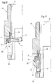
- the device 1 for holding screws 2 when screwing in consists essentially of a component 5 which can be fixed on the housing 3 of a drive unit 4, a screw nut 6 which is designed to accommodate at least a portion of the drive end 7 of a screw 2, and a support part 8, in which at least two support jaws 9, 10 are held.
- the screw nut 6 can be coupled to a drive 11.
- two spaced-apart guide disks 12 and 13 are provided to guide the screw nut 6 within the component 5.
- the right support jaw 10 is shown in its rest position, which also represents the use position.
- the left support jaw 9 is shown in the pivoted back position. In use, of course, both support jaws 9 and 10 are in the same position.
- the support jaws 9, 10 are aligned approximately transversely to the screw-in axis 14 and project freely from their pivot bearing 15, 16 in the direction of the screw-in axis 14. In the direction opposite to the screwing-in direction E, the support jaws 9, 10 are spring-loaded against a stop 17, 18. In the screwing direction E, however, the support jaws 9, 10 are designed to be pivotable.
- the support jaws 9, 10 have a plate-like design and have central, approximately semicircular indentations 19 at their free ends.
- the two indentations 19 form an approximately circular passage opening in which the shaft 20 of the screw 2 to be inserted is held. So that, if necessary, the support jaws 9, 10 can be pivoted without problems even when the screw 2 is inserted or when the same is inserted, the indentations 19 are designed to be approximately semi-conical in the direction of the screw nut 6.
- the support jaws 9, 10 form an acute angle ⁇ with the screw-in axis 14 in their rest position directed towards the screw-in axis 14.
- the support jaws 9, 10 are thus slightly inclined towards the screw nut 6. It is thus ensured that when the support jaws 9, 10 are loaded in the direction transverse to the screw-in axis 14, they cannot pivot downward, but, in contrast, are pressed even more firmly against the corresponding stop 17 or 18.
- the support jaws 9, 10 have inclined end surfaces 21, these inclined end surfaces being able to originate only from one surface 22 or 23 or, as shown, from both surfaces 22, 23. These inclined end faces 21 form an acute angle with the screw-in axis 14, which is towards or away from the screw nut 6 or open on both sides.
- One or two side surfaces 24, 25 merge into the oblique end surfaces 21 with an acute-angled bevel 26, 27, 28 or a corresponding rounding. This enables the shaft 20 to be pressed in from the side.
- the support jaws 9, 10 move downward in the screwing-in direction through these acute-angled bevels and thus allow the shaft 20 of the screw 2 to penetrate into the through opening formed by the indentations 19.
- the support jaws 9, 10 At the end facing away from the indentation 19, the support jaws 9, 10 have bearing eyes 29, 30, so that the bearing in the supporting part 8 can take place via corresponding bolts 31.
- the support part 8 To support and hold the support jaws 9, 10, the support part 8 is designed in a yoke-like manner, its legs 32, 33, which project freely parallel to one another at a distance, have the pivot bearings 15, 16 and the stops 17, 18 for the support jaws 9, 10.
- the support jaws 9, 10 are held so as to be pivotable through an angle of approximately 90.degree Legs 32, 33 can be swung in.
- the support jaw 9 shown has not yet been fully pivoted into the leg 33, and could therefore be moved further. This pivoting movement can take place until the support jaw 9 comes into contact with a section 35 that is indented for this purpose at the stop 17.
- the free ends of the legs 32, 33 are also suitable for serving as supports and for support on the workpiece to be screwed.
- the support part 8 is telescopic on the component 5 which can be fixed on the drive unit 4, i.e. on a tubular body 39 of the same, guided.
- the supporting part 8 is held in a lower rest position by means of a helical spring 40.
- the component 5 is pushed into the supporting part 8, namely until a stop ring 37 abuts a stop element 38.
- the special arrangement and design of the support jaws 9 and 10 is particularly important for the device 1 described here, although further design variants are possible. Modifications would be conceivable here, both in terms of design and form. It would thus be possible for the support jaws 9, 10 to also be designed to be pivotable to both sides, that is to say in the direction and counter to the screwing-in direction, in which case a spring-loaded design ensures that the support jaws are always returned to the corresponding rest position. In this context, it would also be conceivable for the support jaws 9, 10 to be held releasably in their rest position by means of a spring-loaded locking part.
Applications Claiming Priority (2)
| Application Number | Priority Date | Filing Date | Title |
|---|---|---|---|
| DE4037547A DE4037547C1 (fr) | 1990-11-26 | 1990-11-26 | |
| DE4037547 | 1990-11-26 |
Publications (2)
| Publication Number | Publication Date |
|---|---|
| EP0487957A1 true EP0487957A1 (fr) | 1992-06-03 |
| EP0487957B1 EP0487957B1 (fr) | 1995-10-18 |
Family
ID=6418925
Family Applications (1)
| Application Number | Title | Priority Date | Filing Date |
|---|---|---|---|
| EP91119050A Expired - Lifetime EP0487957B1 (fr) | 1990-11-26 | 1991-11-08 | Dispositif pour maintenir des vis pendant le serrage |
Country Status (3)
| Country | Link |
|---|---|
| EP (1) | EP0487957B1 (fr) |
| AT (1) | ATE129177T1 (fr) |
| DE (2) | DE4037547C1 (fr) |
Cited By (3)
| Publication number | Priority date | Publication date | Assignee | Title |
|---|---|---|---|---|
| EP1099495A2 (fr) * | 1999-11-13 | 2001-05-16 | ECKOLD GmbH & Co. KG | Dispositif d'assemblage mécanique de plaques superposées au moyen de pièces d'assemblage auxiliaires |
| DE10242511A1 (de) * | 2002-09-12 | 2004-04-08 | Gedore-Werkzeugfabrik Otto Dowidat Kg | Schraubwerkzeug insbesondere Schlag-Ringschlüssel |
| DE10348427A1 (de) * | 2003-10-14 | 2005-05-19 | Volkswagen Ag | Verfahren und Vorrichtung zur Direktverschraubung |
Families Citing this family (1)
| Publication number | Priority date | Publication date | Assignee | Title |
|---|---|---|---|---|
| DE4422725A1 (de) * | 1994-06-29 | 1996-01-04 | Reich Maschf Gmbh Karl | Eintreibgerät für Befestigungsmittel |
Citations (2)
| Publication number | Priority date | Publication date | Assignee | Title |
|---|---|---|---|---|
| FR1573990A (fr) * | 1968-03-18 | 1969-07-11 | ||
| DE3104460A1 (de) * | 1980-11-20 | 1982-06-24 | Automatik & Maskin AB, 70590 Örebro | Geraet zur verwendung an motorisch betriebenen handschraubern zur fuehrung von schraubenzieher und schraube |
Family Cites Families (4)
| Publication number | Priority date | Publication date | Assignee | Title |
|---|---|---|---|---|
| US4003417A (en) * | 1975-07-28 | 1977-01-18 | Leroy Cornwell | Self locking and unlocking clamp for automatic fastener driving tools |
| DE2549601A1 (de) * | 1975-11-05 | 1977-05-12 | Erich Klesatschke | Schrauber zum einschrauben von schrauben o.dgl. |
| DD228769A1 (de) * | 1984-11-16 | 1985-10-23 | Karosseriewerk Halle Werk 2 Ve | Vorsatzwerkzeug zur ausfuehrung unterschiedlicher schraubverbindungen |
| GB2206828B (en) * | 1987-07-14 | 1990-10-31 | Neville John Smith | Screwdriving tool |
-
1990
- 1990-11-26 DE DE4037547A patent/DE4037547C1/de not_active Expired - Fee Related
-
1991
- 1991-11-08 AT AT91119050T patent/ATE129177T1/de not_active IP Right Cessation
- 1991-11-08 EP EP91119050A patent/EP0487957B1/fr not_active Expired - Lifetime
- 1991-11-08 DE DE59106726T patent/DE59106726D1/de not_active Expired - Fee Related
Patent Citations (2)
| Publication number | Priority date | Publication date | Assignee | Title |
|---|---|---|---|---|
| FR1573990A (fr) * | 1968-03-18 | 1969-07-11 | ||
| DE3104460A1 (de) * | 1980-11-20 | 1982-06-24 | Automatik & Maskin AB, 70590 Örebro | Geraet zur verwendung an motorisch betriebenen handschraubern zur fuehrung von schraubenzieher und schraube |
Cited By (4)
| Publication number | Priority date | Publication date | Assignee | Title |
|---|---|---|---|---|
| EP1099495A2 (fr) * | 1999-11-13 | 2001-05-16 | ECKOLD GmbH & Co. KG | Dispositif d'assemblage mécanique de plaques superposées au moyen de pièces d'assemblage auxiliaires |
| EP1099495A3 (fr) * | 1999-11-13 | 2002-01-02 | ECKOLD GmbH & Co. KG | Dispositif d'assemblage mécanique de plaques superposées au moyen de pièces d'assemblage auxiliaires |
| DE10242511A1 (de) * | 2002-09-12 | 2004-04-08 | Gedore-Werkzeugfabrik Otto Dowidat Kg | Schraubwerkzeug insbesondere Schlag-Ringschlüssel |
| DE10348427A1 (de) * | 2003-10-14 | 2005-05-19 | Volkswagen Ag | Verfahren und Vorrichtung zur Direktverschraubung |
Also Published As
| Publication number | Publication date |
|---|---|
| ATE129177T1 (de) | 1995-11-15 |
| DE4037547C1 (fr) | 1992-01-23 |
| EP0487957B1 (fr) | 1995-10-18 |
| DE59106726D1 (de) | 1995-11-23 |
Similar Documents
| Publication | Publication Date | Title |
|---|---|---|
| DE3312141C2 (fr) | ||
| DE2341642A1 (de) | Spannfutter fuer bohrer | |
| EP0134975A1 (fr) | Mandrin pour la fixation de pièces d'un outil, notamment d'un tournevis | |
| DE10147588A1 (de) | Befestigungskloben zur Halterung von Gegenständen an einer Profilschiene | |
| EP0521490B1 (fr) | Arrangement de deux éléments de construction connectés télescopiquement l'un avec l'autre | |
| EP0949424A2 (fr) | Raccord entre composants, en particulier pour panneaux | |
| EP0572607B1 (fr) | Dispositif d'insertion et de pose de rivets aveugles tirants autoforeurs | |
| EP0942806A1 (fr) | Douille de clef pour loger la tete d'un element de fixation ou a introduire dans la tete d'un element de fixation | |
| DE19813084C1 (de) | Schneidwerkzeug, insbesondere Hobelmesserkopf oder Hobelmesserwelle | |
| DE2549868A1 (de) | Vorrichtung zur schraubenbefestigung | |
| DE3938689A1 (de) | Spannzangenhalter | |
| DE19643407C2 (de) | Vorrichtung zum Halten zweier Bauteile in einer Abstandslage zueinander | |
| EP0487957B1 (fr) | Dispositif pour maintenir des vis pendant le serrage | |
| EP0248101B1 (fr) | Mécanisme d'alimentation des éléments de fixation montés sur une bande à un outil de pose de tels éléments | |
| DE4244603A1 (de) | Klemmverbinder | |
| DE4112618C2 (fr) | ||
| EP1321589A2 (fr) | Ferrure de fixation pour fixation sanitaire | |
| EP1488989A2 (fr) | Fermeture à barre rotative pour portes, ridelles ou semblables de superstuctures de véhicules utilitaires | |
| DE102004056091B4 (de) | Orthopädische Fixationsvorrichtung und orthopädisches Fixationssystem | |
| DE3304206C2 (fr) | ||
| CH622200A5 (en) | Cutting tool, in particular for a lathe | |
| WO1999050028A1 (fr) | Element de tournevis | |
| DE112008003661B4 (de) | Dübelbolzen einer Verbindungsvorrichtung | |
| DE3442322C2 (fr) | ||
| DE202004018037U1 (de) | Orthopädische Fixationsvorrichtung und orthopädisches Fixationssystem |
Legal Events
| Date | Code | Title | Description |
|---|---|---|---|
| PUAI | Public reference made under article 153(3) epc to a published international application that has entered the european phase |
Free format text: ORIGINAL CODE: 0009012 |
|
| AK | Designated contracting states |
Kind code of ref document: A1 Designated state(s): AT BE CH DE DK ES FR GB IT LI NL SE |
|
| 17P | Request for examination filed |
Effective date: 19921107 |
|
| RAP1 | Party data changed (applicant data changed or rights of an application transferred) |
Owner name: SFS INDUSTRIE HOLDING AG |
|
| 17Q | First examination report despatched |
Effective date: 19940816 |
|
| GRAA | (expected) grant |
Free format text: ORIGINAL CODE: 0009210 |
|
| AK | Designated contracting states |
Kind code of ref document: B1 Designated state(s): AT BE CH DE DK ES FR GB IT LI NL SE |
|
| PG25 | Lapsed in a contracting state [announced via postgrant information from national office to epo] |
Ref country code: IT Free format text: LAPSE BECAUSE OF FAILURE TO SUBMIT A TRANSLATION OF THE DESCRIPTION OR TO PAY THE FEE WITHIN THE PRE;WARNING: LAPSES OF ITALIAN PATENTS WITH EFFECTIVE DATE BEFORE 2007 MAY HAVE OCCURRED AT ANY TIME BEFORE 2007. THE CORRECT EFFECTIVE DATE MAY BE DIFFERENT FROM THE ONE RECORDED.SCRIBED TIME-LIMIT Effective date: 19951018 Ref country code: DK Effective date: 19951018 Ref country code: ES Free format text: THE PATENT HAS BEEN ANNULLED BY A DECISION OF A NATIONAL AUTHORITY Effective date: 19951018 Ref country code: NL Free format text: LAPSE BECAUSE OF NON-PAYMENT OF DUE FEES Effective date: 19951018 Ref country code: BE Effective date: 19951018 |
|
| REF | Corresponds to: |
Ref document number: 129177 Country of ref document: AT Date of ref document: 19951115 Kind code of ref document: T |
|
| REF | Corresponds to: |
Ref document number: 59106726 Country of ref document: DE Date of ref document: 19951123 |
|
| ET | Fr: translation filed | ||
| GBT | Gb: translation of ep patent filed (gb section 77(6)(a)/1977) |
Effective date: 19960125 |
|
| NLV1 | Nl: lapsed or annulled due to failure to fulfill the requirements of art. 29p and 29m of the patents act | ||
| PLBE | No opposition filed within time limit |
Free format text: ORIGINAL CODE: 0009261 |
|
| STAA | Information on the status of an ep patent application or granted ep patent |
Free format text: STATUS: NO OPPOSITION FILED WITHIN TIME LIMIT |
|
| 26N | No opposition filed | ||
| REG | Reference to a national code |
Ref country code: GB Ref legal event code: IF02 |
|
| PGFP | Annual fee paid to national office [announced via postgrant information from national office to epo] |
Ref country code: AT Payment date: 20041112 Year of fee payment: 14 |
|
| REG | Reference to a national code |
Ref country code: CH Ref legal event code: NV Representative=s name: JUERG PLUESS SFS INTEC AG INTELLECTUAL PROPERTY MA |
|
| PG25 | Lapsed in a contracting state [announced via postgrant information from national office to epo] |
Ref country code: AT Free format text: LAPSE BECAUSE OF NON-PAYMENT OF DUE FEES Effective date: 20051108 |
|
| PGFP | Annual fee paid to national office [announced via postgrant information from national office to epo] |
Ref country code: CH Payment date: 20061010 Year of fee payment: 16 |
|
| PGFP | Annual fee paid to national office [announced via postgrant information from national office to epo] |
Ref country code: GB Payment date: 20061025 Year of fee payment: 16 |
|
| PGFP | Annual fee paid to national office [announced via postgrant information from national office to epo] |
Ref country code: SE Payment date: 20061110 Year of fee payment: 16 |
|
| PGFP | Annual fee paid to national office [announced via postgrant information from national office to epo] |
Ref country code: DE Payment date: 20061122 Year of fee payment: 16 |
|
| PGFP | Annual fee paid to national office [announced via postgrant information from national office to epo] |
Ref country code: FR Payment date: 20061127 Year of fee payment: 16 |
|
| EUG | Se: european patent has lapsed | ||
| GBPC | Gb: european patent ceased through non-payment of renewal fee |
Effective date: 20071108 |
|
| PG25 | Lapsed in a contracting state [announced via postgrant information from national office to epo] |
Ref country code: CH Free format text: LAPSE BECAUSE OF NON-PAYMENT OF DUE FEES Effective date: 20071130 Ref country code: LI Free format text: LAPSE BECAUSE OF NON-PAYMENT OF DUE FEES Effective date: 20071130 |
|
| REG | Reference to a national code |
Ref country code: CH Ref legal event code: PL |
|
| PG25 | Lapsed in a contracting state [announced via postgrant information from national office to epo] |
Ref country code: SE Free format text: LAPSE BECAUSE OF NON-PAYMENT OF DUE FEES Effective date: 20071109 Ref country code: DE Free format text: LAPSE BECAUSE OF NON-PAYMENT OF DUE FEES Effective date: 20080603 |
|
| REG | Reference to a national code |
Ref country code: FR Ref legal event code: ST Effective date: 20080930 |
|
| PG25 | Lapsed in a contracting state [announced via postgrant information from national office to epo] |
Ref country code: GB Free format text: LAPSE BECAUSE OF NON-PAYMENT OF DUE FEES Effective date: 20071108 |
|
| PG25 | Lapsed in a contracting state [announced via postgrant information from national office to epo] |
Ref country code: FR Free format text: LAPSE BECAUSE OF NON-PAYMENT OF DUE FEES Effective date: 20071130 |