EP0483712B1 - Verschliessmaschine für Behälter - Google Patents
Verschliessmaschine für Behälter Download PDFInfo
- Publication number
- EP0483712B1 EP0483712B1 EP91118324A EP91118324A EP0483712B1 EP 0483712 B1 EP0483712 B1 EP 0483712B1 EP 91118324 A EP91118324 A EP 91118324A EP 91118324 A EP91118324 A EP 91118324A EP 0483712 B1 EP0483712 B1 EP 0483712B1
- Authority
- EP
- European Patent Office
- Prior art keywords
- containers
- closure application
- axes
- cylindrical body
- conveyor
- Prior art date
- Legal status (The legal status is an assumption and is not a legal conclusion. Google has not performed a legal analysis and makes no representation as to the accuracy of the status listed.)
- Expired - Lifetime
Links
Images
Classifications
-
- B—PERFORMING OPERATIONS; TRANSPORTING
- B67—OPENING, CLOSING OR CLEANING BOTTLES, JARS OR SIMILAR CONTAINERS; LIQUID HANDLING
- B67C—CLEANING, FILLING WITH LIQUIDS OR SEMILIQUIDS, OR EMPTYING, OF BOTTLES, JARS, CANS, CASKS, BARRELS, OR SIMILAR CONTAINERS, NOT OTHERWISE PROVIDED FOR; FUNNELS
- B67C7/00—Concurrent cleaning, filling, and closing of bottles; Processes or devices for at least two of these operations
- B67C7/0006—Conveying; Synchronising
- B67C7/004—Conveying; Synchronising the containers travelling along a circular path
-
- B—PERFORMING OPERATIONS; TRANSPORTING
- B65—CONVEYING; PACKING; STORING; HANDLING THIN OR FILAMENTARY MATERIAL
- B65B—MACHINES, APPARATUS OR DEVICES FOR, OR METHODS OF, PACKAGING ARTICLES OR MATERIALS; UNPACKING
- B65B43/00—Forming, feeding, opening or setting-up containers or receptacles in association with packaging
- B65B43/42—Feeding or positioning bags, boxes, or cartons in the distended, opened, or set-up state; Feeding preformed rigid containers, e.g. tins, capsules, glass tubes, glasses, to the packaging position; Locating containers or receptacles at the filling position; Supporting containers or receptacles during the filling operation
- B65B43/54—Means for supporting containers or receptacles during the filling operation
-
- B—PERFORMING OPERATIONS; TRANSPORTING
- B67—OPENING, CLOSING OR CLEANING BOTTLES, JARS OR SIMILAR CONTAINERS; LIQUID HANDLING
- B67C—CLEANING, FILLING WITH LIQUIDS OR SEMILIQUIDS, OR EMPTYING, OF BOTTLES, JARS, CANS, CASKS, BARRELS, OR SIMILAR CONTAINERS, NOT OTHERWISE PROVIDED FOR; FUNNELS
- B67C7/00—Concurrent cleaning, filling, and closing of bottles; Processes or devices for at least two of these operations
- B67C7/0006—Conveying; Synchronising
- B67C2007/0066—Devices particularly adapted for container closing
Definitions
- the present invention relates to an apparatus for applying closures to containers.
- the present invention relates to an apparatus for applying closures to containers, such as bottles, flasks and the like, the neck whereof is inclined with respect to a vertical longitudinal axis of said containers.
- the containers are rotated by the related grip elements so that they become arranged with their neck arranged vertically.
- This arrangement in fact facilitates the subsequent closure application operation, which occurs on another rotating closure-fitting carousel.
- said input carousel must have very small dimensions, and the described rotation of the containers occurs while said containers, supported by the grip elements, move along a rather small arc, for example equal to 45 o .
- a consequence of this is the fact that said rotation of the containers is performed in a very rapid manner, and this fact often gives rise to an escape of liquid from said containers.
- EP-A-345 470 discloses a washing machine for ampoules in which the empty ampoules are handled by a circumferential conveyer and upturned in a sudden manner for directing them towards underlying washing means.
- the aim of the present invention is to provide an apparatus which is suitable for applying closures to containers having a neck which is inclined with respect to respective axes of said containers, which does not have the disadvantages described with reference to the known art.
- an apparatus for applying closures to containers which have an inclined mouth with respect to an axis of said containers and having the features set forth in claim 1.
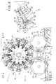
- the reference numeral 1 generally indicates a filling machine which is only partially illustrated and is suitable for filling with liquid substances and for applying closures to containers 2 which have a mouth 3 which is inclined with respect to an axis of said containers 2.
- the machine 1 comprises an apparatus 1' for applying closures to containers, which in turn comprises feeder means which are constituted by a horizontal belt conveyor 4 which is flanked and partially surmounted by a worm or auger conveyor 5 motorized by a motor 6, which is capable of transferring in succession the containers 2 (already filled with liquid by parts of the machine 1 which are not illustrated) toward a rotary conveyor 7 which is adapted for transferring the containers 2 along a circular path.
- feeder means which are constituted by a horizontal belt conveyor 4 which is flanked and partially surmounted by a worm or auger conveyor 5 motorized by a motor 6, which is capable of transferring in succession the containers 2 (already filled with liquid by parts of the machine 1 which are not illustrated) toward a rotary conveyor 7 which is adapted for transferring the containers 2 along a circular path.
- the conveyor 7 transfers in succession the containers 2 to a rotary closure application conveyor or closure application carousel 8, which applies closures 9 to the containers 2 and transfers the closure-fitted containers 2, at an output station 7'', to a further rotary output conveyor 10 which transports the containers 2 onto a horizontal belt conveyor 11 which is suitable for sending said containers toward further processing stations which are not illustrated.
- the rotary conveyor 7 essentially comprises a drum 12 with a vertical axis, which has a clockwise rotary motion (with reference to figure 1) and is provided, on its periphery, with a plurality of mutually equidistant recesses 13, each of which is suitable for accommodating a container 2 which is arranged so that said axis thereof is vertical.
- the periphery of the drum 12 is flanked by a curved fixed guide 14 which has the purpose of keeping the containers 2 within the recesses 13 during their transfer by means of the conveyor 7.
- the closure application carousel 8 comprises (see also figure 3) a substantially cylindrical conveyance head 15 which counter-rotates with respect to the conveyor 7 and is substantially tangent thereto.
- the rotating conveyor 10 essentially comprises a drum 16 with a vertical axis which rotates clockwise (with reference to figure 1) and is provided, on its periphery, with a plurality of mutually equidistant recesses 17, each of which is suitable for accommodating a container 2 which arrives from the closure application carousel 8 and is arranged so that said axis thereof is vertical.
- the periphery of the drum 16 is flanked by a fixed curved guide 18 which maintains the containers 2 within the recesses 17 during their transfer by means of the conveyor 10.
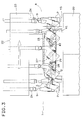
- the closure application carousel 8 comprises a vertical shaft 19 which is rotatably supported by the base 20 of the machine 1 and is connected, in a manner which is not illustrated, to motor means which are not illustrated.
- the shaft 19 supports, in a manner which is not illustrated, a hollow cylindrical body 21 which is coaxial thereto; a known closure application unit 22 is connected to the upper end of said body 21 and is not described in detail hereinafter, since it does not per se constitute the subject of the present invention; said closure application unit essentially comprises a cylindrical body 23 which is coaxial to the shaft 19 and from the lower face of which mutually angularly equidistantly spaced known closure application means or closure application heads 24 extend downward.
- Each closure application head 24, in order to apply a closure to a container 2 is capable, under the action of actuation means which are not illustrated, of sliding vertically along its own axis and of rotating in both directions about said axis.
- the hollow cylindrical body 21 is radially traversed, at a level which is substantially equal to that of a median portion of the containers 2 carried by the conveyor 7, by a plurality of mutually equidistantly spaced holes 25.
- each hole 25 is coaxially traversed by a bush 26 inside which a tubular body 27 is rotatably accommodated; an end of a lever 28, which supports a cam-follower roller 29 with its own free end, is connected to said body 27 inside the cylindrical body 21.
- a pin 30 is slidingly mounted within each tubular body 27 and supports, at one of its ends which is internal to the hollow cylindrical body 21, a disk 31, which is coaxial thereto and rigidly associated therewith, and a cam-follower roller 32.
- a helical spring 33 which acts by compression is interposed between the disk 31 and an abutment surface of the tubular body 27, and is wound around a portion of the pin 30.
- Two racks 34 are defined on the other end of the pin 30 outside the tubular body 27, extend parallel to the axis of said pin 30 and are arranged on opposite sides with respect to said axis.
- the end of the tubular body 27 which is external to the hollow cylindrical body 21 supports a tab 35 on which the ends of two substantially L-shaped jaws 37 are pivoted by means of respective pivots 36.
- Each jaw 37 is provided, proximate to its portion which is engaged in the pivot 36, with a set of teeth 38 which extends along an arc of a circle and engages one of the racks 34.
- Each pair of mutually adjacent jaws 37 constitutes what will be referred to hereinafter as a clamp or grip means 37'.
- the base 20 of the machine 1 supports, coaxially to the shaft 19 and inside the hollow cylindrical body 21, a fixed cam 39 which has a lateral track 40, which is suitable for being engaged by the rollers 32, and a fixed cam 41, an upper track whereof 42 is adapted for being followed by the rollers 29.
- cam-follower rollers 29 and the cam 41 are also termed, hereinafter, actuation means of the grip means 37', since they can impart to said grip means 37' an oscillation in both directions between a first position and a second position, at which said axes of the related containers 2 and, respectively, the axes of the mouths 3 of said containers 2 are arranged substantially vertical.
- the containers 2 to which the closure is to be applied are guided in succession by the belt conveyor 4 and by the scroll conveyor 5 into respective recesses 13 of the rotary conveyor 7.
- Said conveyor 7 then sends the containers 2 in succession between the jaws 37 of respective clamps 37' of the closure application unit 22; each clamp firmly grips a container 2, in a manner which is clearly illustrated in figure 2, by virtue of the action of the cam 39 on the related roller 32 and of said meshing between the racks 34 and the sets of teeth 38.
- each clamp 37' is kept, by virtue of the action of the cam 41 on the roller 29, in such as position as to allow the accommodation of a vertically arranged container 2.
- each clamp 37' After the arrival of each container 2 between the jaws 37 of a clamp 37' at the input station 7', as the closure application carousel 8 continues to rotate, the cam 41 produces a rotation of each clamp 37' about the axis of the pin 30 which is such as to incline the related container 2 and arrange it so that the axis of its mouth 3 is vertical.
- the axis of the pin 30, about which said rotation occurs, is substantially radial with respect to the closure application carousel 8.
- each clamp 37' opens and transfers the related closure-fitted container 2 to a recess 17 of the output conveyor 10, which in turn transfers the containers 2 to the belt conveyor 11.
- the conveyors 7 and 10 and the conveyance head 15 may be replaced with linear conveyors which are capable of transferring containers 2 to one other in a manner similar to the one described.
- the described movements of the grip means 37' may furthermore be produced by actuation means of any type, different from those described, and said grip means 37' may be made in a different manner from the one described.
Claims (3)
- Vorrichtung zum Anbringen von Verschlüssen (9) an Behältern (2) mit einer Mündung (3), die in Bezug auf eine Achse der genannten Behälter (2) geneigt ist, aufweisend: erste Fördermittel (7) und zweite Fördermittel (10) zum Überführen der genannten Behälter (2) in Aufeinanderfolge, welche so angeordnet sind, daß deren genannten Achsen vertikal sind, und einen Verschlußanbringungsförderer (8), der dazu befähigt ist, die genannten Behälter (2) von den genannten ersten Fördermitteln (7) aufzunehmen, und der zu deren Überführung zu den genannten zweiten Fördermitteln (10) befähigt ist; wobei der genannte Verschlußanbringungsförderer (8) Mittel (37') zum Ergreifen der von den genannten ersten Fördermitteln (7) ankommenden Behälter (2) und Betätigungsmittel (41, 29) aufweist, um den genannten Greifmitteln (37') eine Oszillation in beiden Richtungen zwischen einer ersten Stellung und einer zweiten Stellung aufzulegen, bei welcher die genannten Achsen der zugeordneten Behälter (2) und jeweils die Achsen der Mündungen (3) der genannten Behälter (2) im wesentlichen vertikal angeordnet sind; wobei der Verschlußanbringungsförderer (8) Verschlußanbringungsmittel (24) aufweist, die dazu befähigt sind, die genannten zugeordneten Verschlüsse (9) an den genannten Behältern (2) anzubringen, während die Achsen der Mündungen (3) der genannten Behälter (2) im wesentlichen vertikal angeordnet sind, dadurch gekennzeichnet, daß die genannten Betätigungsmittel (41, 29) Nockenmittel (41) aufweisen, welche kontinuierliche Führungsbahnmittel (42) definieren, die sich entlang einer Basis (20) des genannten Verschlußanbringungsförderers (8) erstrecken, und Nockenfolgemittel (29) aufweisen, welche den genannten Greifmitteln (37') zugeordnet und dazu befähigt sind, während der Überführung der genannten Behälter (2) zwischen den genannten ersten Fördermitteln (7) und den genannten zweiten Fördermitteln (10) mit den genannten Führungsbahnmitteln (42) in Eingriff zu gelangen, wobei der genannte Verschlußanbringungsförderer durch ein rotierendes Karussell (8) gebildet ist, welches eine Mehrzahl der genannten Greifmittel (37') trägt, welche sich in gegenseitigem gleichmäßigen Abstand befinden und von welchen ein jedes dazu befähigt ist, um eine jeweilige Achse zu oszillieren, die im wesentlichen radial in Bezug auf das genannte Karussell (8) ausgerichtet ist, und wobei die genannten Führungsbahnmittel (42) der genannten Nockenmittel (41) dazu befähigt sind, den genannten Greifmitteln (37') die genannte Oszillation aufzulegen, zwischen der genannten ersten Position, in welcher die genannten Achsen der genannten Behälter (2) im wesentlichen vertikal angeordnet sind, und der genannten zweiten Position, in welcher die genannten Achsen der genannten Mündungen (3) im wesentlichen vertikal angeordnet sind, wobei die genannten Verschlußanbringungsmittel (24) dazu befähigt sind, die genannten Verschlüsse (9) an den genannten Behältern (2) während deren Überführung zwischen den genannten ersten (7) und den genannten zweiten (10) Fördermitteln anzubringen.
- Vorrichtung gemäß Anspruch 1, dadurch gekennzeichnet, daß die genannten Greifmittel (37') und die genannten Verschlußanbringungsmittel (24) auf dem genannten Verschlußanbringungsförderer (8) zur Bewegung in entsprechender Beziehung angeordnet sind.
- Vorrichtung gemäß Anspruch 1, dadurch gekennzeichnet, daß die genannten Greifmittel (37') einen rohrförmigen Körper (27) umfassen, der in rotierbarer Weise innerhalb einer Buchse oder Hülse (26) aufgenommen ist, welche in Radialrichtung einen zylindrischen Körper (21) des genannten Verschlußanbringungs-Karussells (8) durchsetzt oder durchquert, sowie ein Ende eines Hebels (28), welcher an seinem freien Ende den genannten Nockenfolger (29) trägt, welcher mit dem genannten rohrförmigen Körper (27) an einem Ende von diesem starr verbunden ist, welches im Inneren des genannten zylindrischen Körpers (21) liegt, um den genannten rohrförmigen Körper (27) nach Drehung des genannten Hebels (28), der durch den genannten Nockenfolger (29) gesteuert wird, der mit den genannten Nockenmitteln (41) in Eingriff steht, zu drehen, wobei ein Stift (30) in verschiebbarer Weise innerhalb des genannten rohrförmigen Körpers (27) angeordnet ist, welcher an einem ersten Ende von diesem, welches innerhalb in Bezug auf den genannten zylindrischen Körper (21) liegt, einen weiteren Nockenfolger (32) trägt, wobei eine Zahnstange (34) an dem zweiten Ende des genannten Stiftes (30) definiert ist, welches außerhalb des genannten zylindrischen Körpers (21) liegt, wobei die genannten Zahnstangen (34) betätigende Klauen (37) an dem genannten rohrförmigen Körper (27) an dessen Ende angelenkt sind, welches außerhalb des genannten zylindrischen Körpers (21) liegt, und wobei die Betätigung der genannten Klauen (37) nach Ineingriffgelangen des genannten weiteren Nockenfolgers (32) durch Nockenmittel (39) stattfindet, die innerhalb des genannten zylindrischen Körpers (21) angeordnet sind.
Applications Claiming Priority (2)
| Application Number | Priority Date | Filing Date | Title |
|---|---|---|---|
| IT371690 | 1990-10-31 | ||
| IT00371690A IT1242601B (it) | 1990-10-31 | 1990-10-31 | Apparecchiatura per l'applicazione di tappi a contenitori. |
Publications (2)
| Publication Number | Publication Date |
|---|---|
| EP0483712A1 EP0483712A1 (de) | 1992-05-06 |
| EP0483712B1 true EP0483712B1 (de) | 1994-12-28 |
Family
ID=11111515
Family Applications (1)
| Application Number | Title | Priority Date | Filing Date |
|---|---|---|---|
| EP91118324A Expired - Lifetime EP0483712B1 (de) | 1990-10-31 | 1991-10-28 | Verschliessmaschine für Behälter |
Country Status (7)
| Country | Link |
|---|---|
| US (1) | US5121587A (de) |
| EP (1) | EP0483712B1 (de) |
| JP (1) | JPH04267790A (de) |
| CA (1) | CA2053968C (de) |
| DE (1) | DE69106317T2 (de) |
| ES (1) | ES2066317T3 (de) |
| IT (1) | IT1242601B (de) |
Families Citing this family (6)
| Publication number | Priority date | Publication date | Assignee | Title |
|---|---|---|---|---|
| CA2096396A1 (en) * | 1993-01-21 | 1994-07-22 | Ronald S. Kaminski | Method and apparatus for trimming and inspecting plastic containers |
| DE102004041749B3 (de) * | 2004-08-28 | 2005-12-15 | Khs Maschinen- Und Anlagenbau Ag | Vorrichtung zum Verschliessen von Flaschen oder dergleichen Behälter |
| KR100652408B1 (ko) * | 2005-04-27 | 2006-12-01 | 삼성전자주식회사 | 베이어 패턴의 디지털 컬러 영상 신호를 처리하는 방법 및장치 |
| US7603828B2 (en) * | 2006-04-26 | 2009-10-20 | Alcoa Closure Systems International, Inc. | Track adjustable mounting assemblies and associated methods |
| EP3153414B1 (de) * | 2015-10-05 | 2018-04-11 | Tetra Laval Holdings & Finance S.A. | Einheit zum aufbringen eines deckels auf einem behälter |
| EP3153413B1 (de) * | 2015-10-05 | 2018-09-19 | Tetra Laval Holdings & Finance S.A. | Verfahren und aufbringungsvorrichtung mit einem aufbringungskopf zum aufbringen eines deckels auf einen behälter |
Family Cites Families (10)
| Publication number | Priority date | Publication date | Assignee | Title |
|---|---|---|---|---|
| DE1482616A1 (de) * | 1965-12-09 | 1969-01-09 | Datz Hermann Dr | Vorrichtung zum mittigen Festhalten von Flaschen verschiedenen Durchmessers in Fuell-,Verschliess- und dergleichen Maschinen |
| DE2055138A1 (de) * | 1970-11-10 | 1972-05-18 | Seeberger KG, Maschinen und Gerätebau, 4272 Kirchhellen | Verfahren und Vorrichtung in einer Abfüllanlage für kanisterartige Gebinde |
| US3729897A (en) * | 1971-08-06 | 1973-05-01 | Champion Int Corp | Pendulum mounted heat seal |
| GB1409734A (en) * | 1972-08-11 | 1975-10-15 | Hill Eng Co Hull Ltd Thomas | Cleaning apparatus for vials bottles and like objects |
| US3882660A (en) * | 1974-05-09 | 1975-05-13 | Pneumatic Scale Corp | Capper with orienting attachment |
| US4018026A (en) * | 1974-05-14 | 1977-04-19 | Mitsubishi Jukogyo Kabushiki Kaisha | Automatic continuous barrel filling method |
| US3955341A (en) * | 1975-10-14 | 1976-05-11 | Horix Manufacturing Company | Apparatus for screwing caps on containers |
| EP0107429A3 (en) * | 1982-10-18 | 1985-03-13 | Metal Closures Limited | Improvements in capping machines for containers |
| US4506489A (en) * | 1983-08-15 | 1985-03-26 | Liqui-Box Corporation | Filler and capper for containers |
| DE3819126A1 (de) * | 1988-06-04 | 1990-02-08 | Bosch Gmbh Robert | Vorrichtung zum reinigen von behaeltern |
-
1990
- 1990-10-31 IT IT00371690A patent/IT1242601B/it active IP Right Grant
-
1991
- 1991-10-22 CA CA002053968A patent/CA2053968C/en not_active Expired - Fee Related
- 1991-10-28 US US07/783,599 patent/US5121587A/en not_active Expired - Lifetime
- 1991-10-28 ES ES91118324T patent/ES2066317T3/es not_active Expired - Lifetime
- 1991-10-28 DE DE69106317T patent/DE69106317T2/de not_active Expired - Fee Related
- 1991-10-28 EP EP91118324A patent/EP0483712B1/de not_active Expired - Lifetime
- 1991-10-30 JP JP3284546A patent/JPH04267790A/ja active Pending
Also Published As
| Publication number | Publication date |
|---|---|
| ES2066317T3 (es) | 1995-03-01 |
| EP0483712A1 (de) | 1992-05-06 |
| DE69106317D1 (de) | 1995-02-09 |
| US5121587A (en) | 1992-06-16 |
| JPH04267790A (ja) | 1992-09-24 |
| CA2053968C (en) | 2002-02-19 |
| DE69106317T2 (de) | 1995-05-24 |
| CA2053968A1 (en) | 1992-05-01 |
| IT9003716A1 (it) | 1992-05-01 |
| IT9003716A0 (it) | 1990-10-31 |
| IT1242601B (it) | 1994-05-16 |
Similar Documents
| Publication | Publication Date | Title |
|---|---|---|
| CA1116142A (en) | Capping apparatus | |
| US3899865A (en) | Wrapping apparatus | |
| US5058731A (en) | Apparatus for conveying products | |
| US4528796A (en) | Apparatus for automatic filling and closing of containers | |
| US3992855A (en) | Automatic wrapping machines | |
| EP2402270B1 (de) | Vorrichtung zum Entladen von Duplex-Produktbeuteln | |
| EP1041034B1 (de) | Greifer für Plastikflaschen | |
| US3755987A (en) | Machine for sealingly closing containers by means of covers | |
| US3587816A (en) | Mechanism for removing containers from mandrels | |
| EP0483712B1 (de) | Verschliessmaschine für Behälter | |
| US4176598A (en) | Printing machines and transfer devices therefor | |
| EP0486439B1 (de) | Anordnung zum synchronen Antrieb von Einrichtungen zur Füllung und Containerbehandlung in Getränkeabfüllern | |
| RU2348574C2 (ru) | Устройство и способ нанесения ярлыков | |
| US4357788A (en) | Method and apparatus for assembling tubular sleeve preforms and containers | |
| US4982554A (en) | Apparatus for applying closures to containers | |
| US2801650A (en) | Filling structure | |
| US4411191A (en) | Centrally mechanically controlled printing machine | |
| US4068450A (en) | Container capping machine | |
| US5157898A (en) | Apparatus for applying closures to containers | |
| JPH0466414A (ja) | 容器処理装置 | |
| CN210683151U (zh) | 一种封口机用导向装置 | |
| JPH03162290A (ja) | 物品の受渡し装置 | |
| JP2004067125A (ja) | グリッパ対、グリッパ、ボトル容器搬送装置 | |
| JP2020063146A (ja) | 容器搬送装置 | |
| JP4158247B2 (ja) | ロータリーホイール |
Legal Events
| Date | Code | Title | Description |
|---|---|---|---|
| PUAI | Public reference made under article 153(3) epc to a published international application that has entered the european phase |
Free format text: ORIGINAL CODE: 0009012 |
|
| AK | Designated contracting states |
Kind code of ref document: A1 Designated state(s): DE ES FR GB |
|
| 17P | Request for examination filed |
Effective date: 19920923 |
|
| 17Q | First examination report despatched |
Effective date: 19921116 |
|
| GRAA | (expected) grant |
Free format text: ORIGINAL CODE: 0009210 |
|
| AK | Designated contracting states |
Kind code of ref document: B1 Designated state(s): DE ES FR GB |
|
| REF | Corresponds to: |
Ref document number: 69106317 Country of ref document: DE Date of ref document: 19950209 |
|
| REG | Reference to a national code |
Ref country code: ES Ref legal event code: FG2A Ref document number: 2066317 Country of ref document: ES Kind code of ref document: T3 |
|
| ET | Fr: translation filed | ||
| PLBE | No opposition filed within time limit |
Free format text: ORIGINAL CODE: 0009261 |
|
| STAA | Information on the status of an ep patent application or granted ep patent |
Free format text: STATUS: NO OPPOSITION FILED WITHIN TIME LIMIT |
|
| 26N | No opposition filed | ||
| REG | Reference to a national code |
Ref country code: GB Ref legal event code: IF02 |
|
| PGFP | Annual fee paid to national office [announced via postgrant information from national office to epo] |
Ref country code: DE Payment date: 20081201 Year of fee payment: 18 |
|
| PGFP | Annual fee paid to national office [announced via postgrant information from national office to epo] |
Ref country code: ES Payment date: 20081027 Year of fee payment: 18 |
|
| PGFP | Annual fee paid to national office [announced via postgrant information from national office to epo] |
Ref country code: FR Payment date: 20081018 Year of fee payment: 18 |
|
| PGFP | Annual fee paid to national office [announced via postgrant information from national office to epo] |
Ref country code: GB Payment date: 20081029 Year of fee payment: 18 |
|
| REG | Reference to a national code |
Ref country code: FR Ref legal event code: ST Effective date: 20100630 |
|
| PG25 | Lapsed in a contracting state [announced via postgrant information from national office to epo] |
Ref country code: FR Free format text: LAPSE BECAUSE OF NON-PAYMENT OF DUE FEES Effective date: 20091102 Ref country code: DE Free format text: LAPSE BECAUSE OF NON-PAYMENT OF DUE FEES Effective date: 20100501 |
|
| PG25 | Lapsed in a contracting state [announced via postgrant information from national office to epo] |
Ref country code: GB Free format text: LAPSE BECAUSE OF NON-PAYMENT OF DUE FEES Effective date: 20091028 |
|
| REG | Reference to a national code |
Ref country code: ES Ref legal event code: FD2A Effective date: 20110307 |
|
| PG25 | Lapsed in a contracting state [announced via postgrant information from national office to epo] |
Ref country code: ES Free format text: LAPSE BECAUSE OF NON-PAYMENT OF DUE FEES Effective date: 20110304 |
|
| PG25 | Lapsed in a contracting state [announced via postgrant information from national office to epo] |
Ref country code: ES Free format text: LAPSE BECAUSE OF NON-PAYMENT OF DUE FEES Effective date: 20091029 |