EP0483712B1 - Apparatus for applying closures to containers - Google Patents
Apparatus for applying closures to containers Download PDFInfo
- Publication number
- EP0483712B1 EP0483712B1 EP91118324A EP91118324A EP0483712B1 EP 0483712 B1 EP0483712 B1 EP 0483712B1 EP 91118324 A EP91118324 A EP 91118324A EP 91118324 A EP91118324 A EP 91118324A EP 0483712 B1 EP0483712 B1 EP 0483712B1
- Authority
- EP
- European Patent Office
- Prior art keywords
- containers
- closure application
- axes
- cylindrical body
- conveyor
- Prior art date
- Legal status (The legal status is an assumption and is not a legal conclusion. Google has not performed a legal analysis and makes no representation as to the accuracy of the status listed.)
- Expired - Lifetime
Links
Images
Classifications
-
- B—PERFORMING OPERATIONS; TRANSPORTING
- B67—OPENING, CLOSING OR CLEANING BOTTLES, JARS OR SIMILAR CONTAINERS; LIQUID HANDLING
- B67C—CLEANING, FILLING WITH LIQUIDS OR SEMILIQUIDS, OR EMPTYING, OF BOTTLES, JARS, CANS, CASKS, BARRELS, OR SIMILAR CONTAINERS, NOT OTHERWISE PROVIDED FOR; FUNNELS
- B67C7/00—Concurrent cleaning, filling, and closing of bottles; Processes or devices for at least two of these operations
- B67C7/0006—Conveying; Synchronising
- B67C7/004—Conveying; Synchronising the containers travelling along a circular path
-
- B—PERFORMING OPERATIONS; TRANSPORTING
- B65—CONVEYING; PACKING; STORING; HANDLING THIN OR FILAMENTARY MATERIAL
- B65B—MACHINES, APPARATUS OR DEVICES FOR, OR METHODS OF, PACKAGING ARTICLES OR MATERIALS; UNPACKING
- B65B43/00—Forming, feeding, opening or setting-up containers or receptacles in association with packaging
- B65B43/42—Feeding or positioning bags, boxes, or cartons in the distended, opened, or set-up state; Feeding preformed rigid containers, e.g. tins, capsules, glass tubes, glasses, to the packaging position; Locating containers or receptacles at the filling position; Supporting containers or receptacles during the filling operation
- B65B43/54—Means for supporting containers or receptacles during the filling operation
-
- B—PERFORMING OPERATIONS; TRANSPORTING
- B67—OPENING, CLOSING OR CLEANING BOTTLES, JARS OR SIMILAR CONTAINERS; LIQUID HANDLING
- B67C—CLEANING, FILLING WITH LIQUIDS OR SEMILIQUIDS, OR EMPTYING, OF BOTTLES, JARS, CANS, CASKS, BARRELS, OR SIMILAR CONTAINERS, NOT OTHERWISE PROVIDED FOR; FUNNELS
- B67C7/00—Concurrent cleaning, filling, and closing of bottles; Processes or devices for at least two of these operations
- B67C7/0006—Conveying; Synchronising
- B67C2007/0066—Devices particularly adapted for container closing
Definitions
- the present invention relates to an apparatus for applying closures to containers.
- the present invention relates to an apparatus for applying closures to containers, such as bottles, flasks and the like, the neck whereof is inclined with respect to a vertical longitudinal axis of said containers.
- the containers are rotated by the related grip elements so that they become arranged with their neck arranged vertically.
- This arrangement in fact facilitates the subsequent closure application operation, which occurs on another rotating closure-fitting carousel.
- said input carousel must have very small dimensions, and the described rotation of the containers occurs while said containers, supported by the grip elements, move along a rather small arc, for example equal to 45 o .
- a consequence of this is the fact that said rotation of the containers is performed in a very rapid manner, and this fact often gives rise to an escape of liquid from said containers.
- EP-A-345 470 discloses a washing machine for ampoules in which the empty ampoules are handled by a circumferential conveyer and upturned in a sudden manner for directing them towards underlying washing means.
- the aim of the present invention is to provide an apparatus which is suitable for applying closures to containers having a neck which is inclined with respect to respective axes of said containers, which does not have the disadvantages described with reference to the known art.
- an apparatus for applying closures to containers which have an inclined mouth with respect to an axis of said containers and having the features set forth in claim 1.
- the reference numeral 1 generally indicates a filling machine which is only partially illustrated and is suitable for filling with liquid substances and for applying closures to containers 2 which have a mouth 3 which is inclined with respect to an axis of said containers 2.
- the machine 1 comprises an apparatus 1' for applying closures to containers, which in turn comprises feeder means which are constituted by a horizontal belt conveyor 4 which is flanked and partially surmounted by a worm or auger conveyor 5 motorized by a motor 6, which is capable of transferring in succession the containers 2 (already filled with liquid by parts of the machine 1 which are not illustrated) toward a rotary conveyor 7 which is adapted for transferring the containers 2 along a circular path.
- feeder means which are constituted by a horizontal belt conveyor 4 which is flanked and partially surmounted by a worm or auger conveyor 5 motorized by a motor 6, which is capable of transferring in succession the containers 2 (already filled with liquid by parts of the machine 1 which are not illustrated) toward a rotary conveyor 7 which is adapted for transferring the containers 2 along a circular path.
- the conveyor 7 transfers in succession the containers 2 to a rotary closure application conveyor or closure application carousel 8, which applies closures 9 to the containers 2 and transfers the closure-fitted containers 2, at an output station 7'', to a further rotary output conveyor 10 which transports the containers 2 onto a horizontal belt conveyor 11 which is suitable for sending said containers toward further processing stations which are not illustrated.
- the rotary conveyor 7 essentially comprises a drum 12 with a vertical axis, which has a clockwise rotary motion (with reference to figure 1) and is provided, on its periphery, with a plurality of mutually equidistant recesses 13, each of which is suitable for accommodating a container 2 which is arranged so that said axis thereof is vertical.
- the periphery of the drum 12 is flanked by a curved fixed guide 14 which has the purpose of keeping the containers 2 within the recesses 13 during their transfer by means of the conveyor 7.
- the closure application carousel 8 comprises (see also figure 3) a substantially cylindrical conveyance head 15 which counter-rotates with respect to the conveyor 7 and is substantially tangent thereto.
- the rotating conveyor 10 essentially comprises a drum 16 with a vertical axis which rotates clockwise (with reference to figure 1) and is provided, on its periphery, with a plurality of mutually equidistant recesses 17, each of which is suitable for accommodating a container 2 which arrives from the closure application carousel 8 and is arranged so that said axis thereof is vertical.
- the periphery of the drum 16 is flanked by a fixed curved guide 18 which maintains the containers 2 within the recesses 17 during their transfer by means of the conveyor 10.
- the closure application carousel 8 comprises a vertical shaft 19 which is rotatably supported by the base 20 of the machine 1 and is connected, in a manner which is not illustrated, to motor means which are not illustrated.
- the shaft 19 supports, in a manner which is not illustrated, a hollow cylindrical body 21 which is coaxial thereto; a known closure application unit 22 is connected to the upper end of said body 21 and is not described in detail hereinafter, since it does not per se constitute the subject of the present invention; said closure application unit essentially comprises a cylindrical body 23 which is coaxial to the shaft 19 and from the lower face of which mutually angularly equidistantly spaced known closure application means or closure application heads 24 extend downward.
- Each closure application head 24, in order to apply a closure to a container 2 is capable, under the action of actuation means which are not illustrated, of sliding vertically along its own axis and of rotating in both directions about said axis.
- the hollow cylindrical body 21 is radially traversed, at a level which is substantially equal to that of a median portion of the containers 2 carried by the conveyor 7, by a plurality of mutually equidistantly spaced holes 25.
- each hole 25 is coaxially traversed by a bush 26 inside which a tubular body 27 is rotatably accommodated; an end of a lever 28, which supports a cam-follower roller 29 with its own free end, is connected to said body 27 inside the cylindrical body 21.
- a pin 30 is slidingly mounted within each tubular body 27 and supports, at one of its ends which is internal to the hollow cylindrical body 21, a disk 31, which is coaxial thereto and rigidly associated therewith, and a cam-follower roller 32.
- a helical spring 33 which acts by compression is interposed between the disk 31 and an abutment surface of the tubular body 27, and is wound around a portion of the pin 30.
- Two racks 34 are defined on the other end of the pin 30 outside the tubular body 27, extend parallel to the axis of said pin 30 and are arranged on opposite sides with respect to said axis.
- the end of the tubular body 27 which is external to the hollow cylindrical body 21 supports a tab 35 on which the ends of two substantially L-shaped jaws 37 are pivoted by means of respective pivots 36.
- Each jaw 37 is provided, proximate to its portion which is engaged in the pivot 36, with a set of teeth 38 which extends along an arc of a circle and engages one of the racks 34.
- Each pair of mutually adjacent jaws 37 constitutes what will be referred to hereinafter as a clamp or grip means 37'.
- the base 20 of the machine 1 supports, coaxially to the shaft 19 and inside the hollow cylindrical body 21, a fixed cam 39 which has a lateral track 40, which is suitable for being engaged by the rollers 32, and a fixed cam 41, an upper track whereof 42 is adapted for being followed by the rollers 29.
- cam-follower rollers 29 and the cam 41 are also termed, hereinafter, actuation means of the grip means 37', since they can impart to said grip means 37' an oscillation in both directions between a first position and a second position, at which said axes of the related containers 2 and, respectively, the axes of the mouths 3 of said containers 2 are arranged substantially vertical.
- the containers 2 to which the closure is to be applied are guided in succession by the belt conveyor 4 and by the scroll conveyor 5 into respective recesses 13 of the rotary conveyor 7.
- Said conveyor 7 then sends the containers 2 in succession between the jaws 37 of respective clamps 37' of the closure application unit 22; each clamp firmly grips a container 2, in a manner which is clearly illustrated in figure 2, by virtue of the action of the cam 39 on the related roller 32 and of said meshing between the racks 34 and the sets of teeth 38.
- each clamp 37' is kept, by virtue of the action of the cam 41 on the roller 29, in such as position as to allow the accommodation of a vertically arranged container 2.
- each clamp 37' After the arrival of each container 2 between the jaws 37 of a clamp 37' at the input station 7', as the closure application carousel 8 continues to rotate, the cam 41 produces a rotation of each clamp 37' about the axis of the pin 30 which is such as to incline the related container 2 and arrange it so that the axis of its mouth 3 is vertical.
- the axis of the pin 30, about which said rotation occurs, is substantially radial with respect to the closure application carousel 8.
- each clamp 37' opens and transfers the related closure-fitted container 2 to a recess 17 of the output conveyor 10, which in turn transfers the containers 2 to the belt conveyor 11.
- the conveyors 7 and 10 and the conveyance head 15 may be replaced with linear conveyors which are capable of transferring containers 2 to one other in a manner similar to the one described.
- the described movements of the grip means 37' may furthermore be produced by actuation means of any type, different from those described, and said grip means 37' may be made in a different manner from the one described.
Landscapes
- Engineering & Computer Science (AREA)
- Mechanical Engineering (AREA)
- Sealing Of Jars (AREA)
- Filling Of Jars Or Cans And Processes For Cleaning And Sealing Jars (AREA)
- Specific Conveyance Elements (AREA)
- Closures For Containers (AREA)
- Spray Control Apparatus (AREA)
- Auxiliary Devices For And Details Of Packaging Control (AREA)
Description
- The present invention relates to an apparatus for applying closures to containers.
- In particular, the present invention relates to an apparatus for applying closures to containers, such as bottles, flasks and the like, the neck whereof is inclined with respect to a vertical longitudinal axis of said containers.
- In known apparatuses for applying closures to containers having an inclined neck, the containers, arriving from a filling unit which has filled them with liquid or powder-like substances, are fed in succession, in a vertical arrangement, to grip elements belonging to a rotating input carousel.
- During their permanence on said carousel, the containers are rotated by the related grip elements so that they become arranged with their neck arranged vertically. This arrangement in fact facilitates the subsequent closure application operation, which occurs on another rotating closure-fitting carousel.
- Due to compulsory layout requirements of the apparatuses at issue, said input carousel must have very small dimensions, and the described rotation of the containers occurs while said containers, supported by the grip elements, move along a rather small arc, for example equal to 45o. A consequence of this is the fact that said rotation of the containers is performed in a very rapid manner, and this fact often gives rise to an escape of liquid from said containers.
- The transfer of containers which are inclined with respect to the vertical from the input carousel to the closure application carousel is furthermore much more difficult than the transfer of vertically arranged containers, and the elements involved in this transfer are unavoidably very complicated.
- From the document DE-A-2 055 138 there is known a linear conveyer corresponding to the precharacterizing part of claim 1, in which means are provided for inclining containers with the mouth in a vertical position so that closures may be applied in a discontinuous process. However no measures for avoiding spillage of the product from inside the containers are taken.
- Indicative for the state of the art is also the document EP-A-345 470 which discloses a washing machine for ampoules in which the empty ampoules are handled by a circumferential conveyer and upturned in a sudden manner for directing them towards underlying washing means.
- The aim of the present invention is to provide an apparatus which is suitable for applying closures to containers having a neck which is inclined with respect to respective axes of said containers, which does not have the disadvantages described with reference to the known art.
- According to the present invention, it is provided an apparatus for applying closures to containers which have an inclined mouth with respect to an axis of said containers and having the features set forth in claim 1.
- The present invention will now be described with reference to the accompanying drawings, which illustrate a non-limitative example of embodiment thereof, wherein:
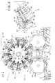
- figure 1 is a schematic plan view, with parts removed for greater clarity, of a portion of a filling machine which includes an apparatus for applying closures to containers, manufactured according to the present invention;
- figure 2 is a partially sectional enlarged-scale view of a detail of figure 1; and
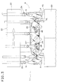
- figure 3 is a schematic elevation view of the apparatus illustrated in figure 1.
- With reference to figure 1, the reference numeral 1 generally indicates a filling machine which is only partially illustrated and is suitable for filling with liquid substances and for applying closures to
containers 2 which have amouth 3 which is inclined with respect to an axis of saidcontainers 2. - The machine 1 comprises an apparatus 1' for applying closures to containers, which in turn comprises feeder means which are constituted by a
horizontal belt conveyor 4 which is flanked and partially surmounted by a worm or auger conveyor 5 motorized by amotor 6, which is capable of transferring in succession the containers 2 (already filled with liquid by parts of the machine 1 which are not illustrated) toward arotary conveyor 7 which is adapted for transferring thecontainers 2 along a circular path. - At an input station 7', the
conveyor 7 transfers in succession thecontainers 2 to a rotary closure application conveyor orclosure application carousel 8, which appliesclosures 9 to thecontainers 2 and transfers the closure-fittedcontainers 2, at an output station 7'', to a furtherrotary output conveyor 10 which transports thecontainers 2 onto ahorizontal belt conveyor 11 which is suitable for sending said containers toward further processing stations which are not illustrated. - The
rotary conveyor 7 essentially comprises adrum 12 with a vertical axis, which has a clockwise rotary motion (with reference to figure 1) and is provided, on its periphery, with a plurality of mutuallyequidistant recesses 13, each of which is suitable for accommodating acontainer 2 which is arranged so that said axis thereof is vertical. The periphery of thedrum 12 is flanked by a curvedfixed guide 14 which has the purpose of keeping thecontainers 2 within therecesses 13 during their transfer by means of theconveyor 7. - The
closure application carousel 8 comprises (see also figure 3) a substantiallycylindrical conveyance head 15 which counter-rotates with respect to theconveyor 7 and is substantially tangent thereto. - The rotating
conveyor 10 essentially comprises adrum 16 with a vertical axis which rotates clockwise (with reference to figure 1) and is provided, on its periphery, with a plurality of mutuallyequidistant recesses 17, each of which is suitable for accommodating acontainer 2 which arrives from theclosure application carousel 8 and is arranged so that said axis thereof is vertical. The periphery of thedrum 16 is flanked by a fixedcurved guide 18 which maintains thecontainers 2 within therecesses 17 during their transfer by means of theconveyor 10. - According to what is illustrated in particular in figures 1 and 3, the
closure application carousel 8 comprises avertical shaft 19 which is rotatably supported by thebase 20 of the machine 1 and is connected, in a manner which is not illustrated, to motor means which are not illustrated. - The
shaft 19 supports, in a manner which is not illustrated, a hollowcylindrical body 21 which is coaxial thereto; a knownclosure application unit 22 is connected to the upper end of saidbody 21 and is not described in detail hereinafter, since it does not per se constitute the subject of the present invention; said closure application unit essentially comprises acylindrical body 23 which is coaxial to theshaft 19 and from the lower face of which mutually angularly equidistantly spaced known closure application means orclosure application heads 24 extend downward. Each closure application head 24, in order to apply a closure to acontainer 2, is capable, under the action of actuation means which are not illustrated, of sliding vertically along its own axis and of rotating in both directions about said axis. - According to what is illustrated in particular in figures 1 and 2, the hollow
cylindrical body 21 is radially traversed, at a level which is substantially equal to that of a median portion of thecontainers 2 carried by theconveyor 7, by a plurality of mutually equidistantly spacedholes 25. According to what is illustrated in particular in figure 2, eachhole 25 is coaxially traversed by abush 26 inside which atubular body 27 is rotatably accommodated; an end of alever 28, which supports a cam-follower roller 29 with its own free end, is connected to saidbody 27 inside thecylindrical body 21. - A
pin 30 is slidingly mounted within eachtubular body 27 and supports, at one of its ends which is internal to the hollowcylindrical body 21, adisk 31, which is coaxial thereto and rigidly associated therewith, and a cam-follower roller 32. Ahelical spring 33 which acts by compression is interposed between thedisk 31 and an abutment surface of thetubular body 27, and is wound around a portion of thepin 30. Tworacks 34 are defined on the other end of thepin 30 outside thetubular body 27, extend parallel to the axis of saidpin 30 and are arranged on opposite sides with respect to said axis. - The end of the
tubular body 27 which is external to the hollowcylindrical body 21 supports atab 35 on which the ends of two substantially L-shaped jaws 37 are pivoted by means of respective pivots 36. Eachjaw 37 is provided, proximate to its portion which is engaged in the pivot 36, with a set ofteeth 38 which extends along an arc of a circle and engages one of theracks 34. Each pair of mutuallyadjacent jaws 37 constitutes what will be referred to hereinafter as a clamp or grip means 37'. - The
base 20 of the machine 1 supports, coaxially to theshaft 19 and inside the hollowcylindrical body 21, afixed cam 39 which has alateral track 40, which is suitable for being engaged by therollers 32, and afixed cam 41, an upper track whereof 42 is adapted for being followed by therollers 29. - The cam-
follower rollers 29 and thecam 41 are also termed, hereinafter, actuation means of the grip means 37', since they can impart to said grip means 37' an oscillation in both directions between a first position and a second position, at which said axes of therelated containers 2 and, respectively, the axes of themouths 3 of saidcontainers 2 are arranged substantially vertical. - In use, the
containers 2 to which the closure is to be applied, filled with liquid and arranged vertically, are guided in succession by thebelt conveyor 4 and by the scroll conveyor 5 intorespective recesses 13 of therotary conveyor 7. - Said
conveyor 7 then sends thecontainers 2 in succession between thejaws 37 of respective clamps 37' of theclosure application unit 22; each clamp firmly grips acontainer 2, in a manner which is clearly illustrated in figure 2, by virtue of the action of thecam 39 on therelated roller 32 and of said meshing between theracks 34 and the sets ofteeth 38. - During this gripping action, each clamp 37' is kept, by virtue of the action of the
cam 41 on theroller 29, in such as position as to allow the accommodation of a vertically arrangedcontainer 2. - After the arrival of each
container 2 between thejaws 37 of a clamp 37' at the input station 7', as theclosure application carousel 8 continues to rotate, thecam 41 produces a rotation of each clamp 37' about the axis of thepin 30 which is such as to incline therelated container 2 and arrange it so that the axis of itsmouth 3 is vertical. The axis of thepin 30, about which said rotation occurs, is substantially radial with respect to theclosure application carousel 8. - With the
containers 2 arranged in this manner, theclosure application heads 24 apply theclosures 9 to theunderlying mouths 3 and, at the end of each closure application operation, thecam 41 causes a rotation of each clamp 37' about the axis of therelated pin 30 which is such as to return therelated container 2 to the original vertical position before it reaches the output station 7''. At said output station 7'', each clamp 37' opens and transfers the related closure-fittedcontainer 2 to arecess 17 of theoutput conveyor 10, which in turn transfers thecontainers 2 to thebelt conveyor 11. - From what has been described, it is evident that the described apparatus is capable of applying
closures 9 tocontainers 2 having a neck which is inclined with respect to the vertical without having the disadvantages described with reference to the known art. - The described rotation of the
containers 2 supported by the clamps 37' in fact occurs more slowly than in known devices, and the transfer of thecontainers 2 from therotary conveyor 7 to theclosure application carousel 8 occurs in a particularly easy manner. - In particular, for example, the
conveyors conveyance head 15 may be replaced with linear conveyors which are capable of transferringcontainers 2 to one other in a manner similar to the one described. - The described movements of the grip means 37' may furthermore be produced by actuation means of any type, different from those described, and said grip means 37' may be made in a different manner from the one described.
Claims (3)
- Apparatus for applying closures (9) to containers (2) having a mouth (3) which is inclined with respect to an axis of said containers (2), comprising first conveyance means (7) and second conveyance means (10) for transferring in succession said containers (2) arranged so that said axes thereof are vertical, and a closure application conveyor (8) adapted for receiving said containers (2) from said first conveyance means (7) and for transferring them to said second conveyance means (10); said closure application conveyor (8) comprising means (37') for gripping the containers (2) arriving from said first conveyance means (7), and actuation means (41, 29) for imparting to said grip means (37') an oscillation in both directions between a first position and a second position at which said axes of the related containers (2) and, respectively, the axes of the mouths (3) of said containers (2) are arranged substantially vertical; the closure application conveyor (8) comprising closure application means (24) adapted for applying said related closures (9) to said containers (2) while the axes of the mouths (3) of said containers (2) are arranged substantially vertical, characterized in that said actuation means (41, 29) comprises cam means (41) defining a continuous track means (42) extending along a base (20) of said closure application conveyor (8) and cam follower means (29) which are associated with said grip means (37') and are adapted for engaging said track means (42) during the transferring of said containers (2) between said first conveyance means (7) and said second conveyance means (10), said closure application conveyor being constituted by a rotating carousel (8) supporting a plurality of said grip means (37') which are mutually equidistant and each of which is adapted for oscillating about a respective axis which is substantially radial with respect to said carousel (8), and said track means (42) of said cam means (41) being adapted for imparting to said grip means (37') said oscillation, between said first position in which said axes of said containers (2) are arranged substantially vertical and said second position in which said axes of said mouths (3) are arranged substantially vertical, said closure application means (24) being adapted to apply said closures (9) to said containers (2) during the transferring thereof between said first (7) and said second (10) conveyance means.
- Apparatus according to claim 1, characterized in that said grip means (37') and said closure application means (24) are mounted on said closure application conveyor (8) for moving in corresponding relationship.
- Apparatus according to claim 1, characterized in that said grip means (37') comprises a tubular body (27) rotatably accommodated in a bush (26) which traverses radially a cylindrical body (21) of said closure application carousel (8), an end of a lever (28) which supports at its free end said cam follower (29) being rigidly connected to said tubular body (27) at an end thereof internal to said cylindrical body (21) for rotating said tubular body (27) upon rotation of said lever (28) controlled by said cam follower (29) engaging said cam means (41), a pin (30) being slidingly mounted within said tubular body (27) supporting at a first end thereof internal to said cylindrical body (21) a further cam follower (32), racks (34) being defined at the second end of said pin (30) which is external to said cylindrical body (21), said racks (34) actuating jaws (37) being pivoted to said tubular body (27) at the end thereof external to said cylindrical body (21), the actuation of said jaws (37) occurring upon engagement of said further cam follower (32) by cam means (39) mounted inside said cylindrical body (21).
Applications Claiming Priority (2)
| Application Number | Priority Date | Filing Date | Title |
|---|---|---|---|
| IT371690 | 1990-10-31 | ||
| IT00371690A IT1242601B (en) | 1990-10-31 | 1990-10-31 | EQUIPMENT FOR THE APPLICATION OF CAPS TO CONTAINERS. |
Publications (2)
| Publication Number | Publication Date |
|---|---|
| EP0483712A1 EP0483712A1 (en) | 1992-05-06 |
| EP0483712B1 true EP0483712B1 (en) | 1994-12-28 |
Family
ID=11111515
Family Applications (1)
| Application Number | Title | Priority Date | Filing Date |
|---|---|---|---|
| EP91118324A Expired - Lifetime EP0483712B1 (en) | 1990-10-31 | 1991-10-28 | Apparatus for applying closures to containers |
Country Status (7)
| Country | Link |
|---|---|
| US (1) | US5121587A (en) |
| EP (1) | EP0483712B1 (en) |
| JP (1) | JPH04267790A (en) |
| CA (1) | CA2053968C (en) |
| DE (1) | DE69106317T2 (en) |
| ES (1) | ES2066317T3 (en) |
| IT (1) | IT1242601B (en) |
Families Citing this family (6)
| Publication number | Priority date | Publication date | Assignee | Title |
|---|---|---|---|---|
| CA2096396A1 (en) * | 1993-01-21 | 1994-07-22 | Ronald S. Kaminski | Method and apparatus for trimming and inspecting plastic containers |
| DE102004041749B3 (en) * | 2004-08-28 | 2005-12-15 | Khs Maschinen- Und Anlagenbau Ag | Device for closing bottles or similar containers |
| KR100652408B1 (en) * | 2005-04-27 | 2006-12-01 | 삼성전자주식회사 | Method and apparatus for processing Bayer-pattern color digital image signal |
| US7603828B2 (en) * | 2006-04-26 | 2009-10-20 | Alcoa Closure Systems International, Inc. | Track adjustable mounting assemblies and associated methods |
| DK3153413T3 (en) * | 2015-10-05 | 2019-01-21 | Tetra Laval Holdings & Finance | PROCEDURE AND MOUNTING MECHANISM, INCLUDING A MOUNTING HEAD FOR, MOUNTING A COVER TO A CONTAINER |
| ES2667704T3 (en) * | 2015-10-05 | 2018-05-14 | Tetra Laval Holdings & Finance S.A. | An applicator unit to apply a lid on a container |
Family Cites Families (10)
| Publication number | Priority date | Publication date | Assignee | Title |
|---|---|---|---|---|
| DE1482616A1 (en) * | 1965-12-09 | 1969-01-09 | Datz Hermann Dr | Device for holding bottles of different diameters in the middle in filling, closing and similar machines |
| DE2055138A1 (en) * | 1970-11-10 | 1972-05-18 | Seeberger KG, Maschinen und Gerätebau, 4272 Kirchhellen | Method and device in a filling plant for canister-like containers |
| US3729897A (en) * | 1971-08-06 | 1973-05-01 | Champion Int Corp | Pendulum mounted heat seal |
| GB1409734A (en) * | 1972-08-11 | 1975-10-15 | Hill Eng Co Hull Ltd Thomas | Cleaning apparatus for vials bottles and like objects |
| US3882660A (en) * | 1974-05-09 | 1975-05-13 | Pneumatic Scale Corp | Capper with orienting attachment |
| US4018026A (en) * | 1974-05-14 | 1977-04-19 | Mitsubishi Jukogyo Kabushiki Kaisha | Automatic continuous barrel filling method |
| US3955341A (en) * | 1975-10-14 | 1976-05-11 | Horix Manufacturing Company | Apparatus for screwing caps on containers |
| EP0107429A3 (en) * | 1982-10-18 | 1985-03-13 | Metal Closures Limited | Improvements in capping machines for containers |
| US4506489A (en) * | 1983-08-15 | 1985-03-26 | Liqui-Box Corporation | Filler and capper for containers |
| DE3819126A1 (en) * | 1988-06-04 | 1990-02-08 | Bosch Gmbh Robert | DEVICE FOR CLEANING CONTAINERS |
-
1990
- 1990-10-31 IT IT00371690A patent/IT1242601B/en active IP Right Grant
-
1991
- 1991-10-22 CA CA002053968A patent/CA2053968C/en not_active Expired - Fee Related
- 1991-10-28 DE DE69106317T patent/DE69106317T2/en not_active Expired - Fee Related
- 1991-10-28 ES ES91118324T patent/ES2066317T3/en not_active Expired - Lifetime
- 1991-10-28 EP EP91118324A patent/EP0483712B1/en not_active Expired - Lifetime
- 1991-10-28 US US07/783,599 patent/US5121587A/en not_active Expired - Lifetime
- 1991-10-30 JP JP3284546A patent/JPH04267790A/en active Pending
Also Published As
| Publication number | Publication date |
|---|---|
| IT9003716A1 (en) | 1992-05-01 |
| JPH04267790A (en) | 1992-09-24 |
| EP0483712A1 (en) | 1992-05-06 |
| IT1242601B (en) | 1994-05-16 |
| DE69106317T2 (en) | 1995-05-24 |
| IT9003716A0 (en) | 1990-10-31 |
| DE69106317D1 (en) | 1995-02-09 |
| CA2053968A1 (en) | 1992-05-01 |
| US5121587A (en) | 1992-06-16 |
| ES2066317T3 (en) | 1995-03-01 |
| CA2053968C (en) | 2002-02-19 |
Similar Documents
| Publication | Publication Date | Title |
|---|---|---|
| CA1116142A (en) | Capping apparatus | |
| US3899865A (en) | Wrapping apparatus | |
| US5058731A (en) | Apparatus for conveying products | |
| EP2402270B1 (en) | Duplex-type product bag unloading apparatus | |
| US3755987A (en) | Machine for sealingly closing containers by means of covers | |
| US4528796A (en) | Apparatus for automatic filling and closing of containers | |
| US3992855A (en) | Automatic wrapping machines | |
| EP1041034B1 (en) | Grippers for plastic bottles | |
| US3587816A (en) | Mechanism for removing containers from mandrels | |
| EP0483712B1 (en) | Apparatus for applying closures to containers | |
| US4176598A (en) | Printing machines and transfer devices therefor | |
| EP0486439B1 (en) | Device for synchronously driving the dispensing and the container handling means in bottling machines | |
| US4357788A (en) | Method and apparatus for assembling tubular sleeve preforms and containers | |
| US4982554A (en) | Apparatus for applying closures to containers | |
| JP7252440B2 (en) | container carrier | |
| US2801650A (en) | Filling structure | |
| US4411191A (en) | Centrally mechanically controlled printing machine | |
| US4068450A (en) | Container capping machine | |
| US5157898A (en) | Apparatus for applying closures to containers | |
| JPH01117126A (en) | Vessel transfer mechanism | |
| JPH0466414A (en) | Receptacle processing device | |
| CN210683151U (en) | Guider for capper | |
| JPH03162290A (en) | Article receiving and delivering apparatus | |
| JP2004067125A (en) | Gripper pair, gripper, and bottle container transfer system | |
| JP4158247B2 (en) | Rotary wheel |
Legal Events
| Date | Code | Title | Description |
|---|---|---|---|
| PUAI | Public reference made under article 153(3) epc to a published international application that has entered the european phase |
Free format text: ORIGINAL CODE: 0009012 |
|
| AK | Designated contracting states |
Kind code of ref document: A1 Designated state(s): DE ES FR GB |
|
| 17P | Request for examination filed |
Effective date: 19920923 |
|
| 17Q | First examination report despatched |
Effective date: 19921116 |
|
| GRAA | (expected) grant |
Free format text: ORIGINAL CODE: 0009210 |
|
| AK | Designated contracting states |
Kind code of ref document: B1 Designated state(s): DE ES FR GB |
|
| REF | Corresponds to: |
Ref document number: 69106317 Country of ref document: DE Date of ref document: 19950209 |
|
| REG | Reference to a national code |
Ref country code: ES Ref legal event code: FG2A Ref document number: 2066317 Country of ref document: ES Kind code of ref document: T3 |
|
| ET | Fr: translation filed | ||
| PLBE | No opposition filed within time limit |
Free format text: ORIGINAL CODE: 0009261 |
|
| STAA | Information on the status of an ep patent application or granted ep patent |
Free format text: STATUS: NO OPPOSITION FILED WITHIN TIME LIMIT |
|
| 26N | No opposition filed | ||
| REG | Reference to a national code |
Ref country code: GB Ref legal event code: IF02 |
|
| PGFP | Annual fee paid to national office [announced via postgrant information from national office to epo] |
Ref country code: DE Payment date: 20081201 Year of fee payment: 18 |
|
| PGFP | Annual fee paid to national office [announced via postgrant information from national office to epo] |
Ref country code: ES Payment date: 20081027 Year of fee payment: 18 |
|
| PGFP | Annual fee paid to national office [announced via postgrant information from national office to epo] |
Ref country code: FR Payment date: 20081018 Year of fee payment: 18 |
|
| PGFP | Annual fee paid to national office [announced via postgrant information from national office to epo] |
Ref country code: GB Payment date: 20081029 Year of fee payment: 18 |
|
| REG | Reference to a national code |
Ref country code: FR Ref legal event code: ST Effective date: 20100630 |
|
| PG25 | Lapsed in a contracting state [announced via postgrant information from national office to epo] |
Ref country code: FR Free format text: LAPSE BECAUSE OF NON-PAYMENT OF DUE FEES Effective date: 20091102 Ref country code: DE Free format text: LAPSE BECAUSE OF NON-PAYMENT OF DUE FEES Effective date: 20100501 |
|
| PG25 | Lapsed in a contracting state [announced via postgrant information from national office to epo] |
Ref country code: GB Free format text: LAPSE BECAUSE OF NON-PAYMENT OF DUE FEES Effective date: 20091028 |
|
| REG | Reference to a national code |
Ref country code: ES Ref legal event code: FD2A Effective date: 20110307 |
|
| PG25 | Lapsed in a contracting state [announced via postgrant information from national office to epo] |
Ref country code: ES Free format text: LAPSE BECAUSE OF NON-PAYMENT OF DUE FEES Effective date: 20110304 |
|
| PG25 | Lapsed in a contracting state [announced via postgrant information from national office to epo] |
Ref country code: ES Free format text: LAPSE BECAUSE OF NON-PAYMENT OF DUE FEES Effective date: 20091029 |