EP0483384A1 - Linearlager - Google Patents
Linearlager Download PDFInfo
- Publication number
- EP0483384A1 EP0483384A1 EP91909372A EP91909372A EP0483384A1 EP 0483384 A1 EP0483384 A1 EP 0483384A1 EP 91909372 A EP91909372 A EP 91909372A EP 91909372 A EP91909372 A EP 91909372A EP 0483384 A1 EP0483384 A1 EP 0483384A1
- Authority
- EP
- European Patent Office
- Prior art keywords
- rolling
- ball
- load
- block
- bearing
- Prior art date
- Legal status (The legal status is an assumption and is not a legal conclusion. Google has not performed a legal analysis and makes no representation as to the accuracy of the status listed.)
- Granted
Links
- 238000005096 rolling process Methods 0.000 claims abstract description 89
- 238000010276 construction Methods 0.000 description 4
- 238000005520 cutting process Methods 0.000 description 3
- 238000001746 injection moulding Methods 0.000 description 3
- 238000003754 machining Methods 0.000 description 3
- 238000004519 manufacturing process Methods 0.000 description 3
- 229920003002 synthetic resin Polymers 0.000 description 3
- 239000000057 synthetic resin Substances 0.000 description 3
- 229910000831 Steel Inorganic materials 0.000 description 2
- 238000005553 drilling Methods 0.000 description 2
- 229920005989 resin Polymers 0.000 description 2
- 239000011347 resin Substances 0.000 description 2
- 239000010959 steel Substances 0.000 description 2
- 230000015572 biosynthetic process Effects 0.000 description 1
- 238000003801 milling Methods 0.000 description 1
- 238000005498 polishing Methods 0.000 description 1
- 230000036316 preload Effects 0.000 description 1
Images


Classifications
-
- F—MECHANICAL ENGINEERING; LIGHTING; HEATING; WEAPONS; BLASTING
- F16—ENGINEERING ELEMENTS AND UNITS; GENERAL MEASURES FOR PRODUCING AND MAINTAINING EFFECTIVE FUNCTIONING OF MACHINES OR INSTALLATIONS; THERMAL INSULATION IN GENERAL
- F16C—SHAFTS; FLEXIBLE SHAFTS; ELEMENTS OR CRANKSHAFT MECHANISMS; ROTARY BODIES OTHER THAN GEARING ELEMENTS; BEARINGS
- F16C29/00—Bearings for parts moving only linearly
- F16C29/04—Ball or roller bearings
- F16C29/06—Ball or roller bearings in which the rolling bodies circulate partly without carrying load
- F16C29/063—Ball or roller bearings in which the rolling bodies circulate partly without carrying load with a bearing body, e.g. a carriage or part thereof, provided between the legs of a U-shaped guide rail or track
-
- Y—GENERAL TAGGING OF NEW TECHNOLOGICAL DEVELOPMENTS; GENERAL TAGGING OF CROSS-SECTIONAL TECHNOLOGIES SPANNING OVER SEVERAL SECTIONS OF THE IPC; TECHNICAL SUBJECTS COVERED BY FORMER USPC CROSS-REFERENCE ART COLLECTIONS [XRACs] AND DIGESTS
- Y10—TECHNICAL SUBJECTS COVERED BY FORMER USPC
- Y10T—TECHNICAL SUBJECTS COVERED BY FORMER US CLASSIFICATION
- Y10T74/00—Machine element or mechanism
- Y10T74/18—Mechanical movements
- Y10T74/18568—Reciprocating or oscillating to or from alternating rotary
- Y10T74/18576—Reciprocating or oscillating to or from alternating rotary including screw and nut
- Y10T74/18656—Carriage surrounded, guided, and primarily supported by member other than screw [e.g., linear guide, etc.]
Definitions
- the present invention relates a linear guide device used, for example, in a linear motion component of a machine tool or an industrial robot.
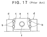
- a linear guide device of a type described above has disclosed in the Japanese Laid-Open Patent publication No. 62-200016.
- a bearing block (a) (will be called merely as a "block") is provided at its opposite side surfaces with load ball grooves (c) in which balls (b) rolls.
- a pair of track beds (d) is disposed with the block (a) therebetween.
- the beds (d) are provided with ball rolling grooves opposed to the load ball grooves (c).
- the balls (b) held between the load ball grooves (c) and the ball rolling grooves support the block (a) so that the block (a) may be movable along the track beds (d).
- a screw shaft (f) of a feed screw mechanism is engaged with a central portion of the block (a), so that the screw shaft (f) may be rotated to move the block (a) along the track beds (d).
- the bearing block for supporting a movable member such as the table is constructed integrally with the feed screw mechanism for applying a driving force for the linea motion to the movable member, a compact construction of the device can be achieved, and a height of the movable member can be minimized, which enables a stable motion.
- each load ball groove must be connected by a ball circulation path so as to guide or introduce the balls from a termination end of the load ball groove to a start end of the load ball groove again.
- the ball circulation path is generally formed of a no-load ball rolling aperture, which is formed in the block to correspond to each load ball groove, and ball return paths, each of which connects an end of the ball load groove and an end of the no-load ball rolling aperture.
- the no-load ball rolling aperture is a very small aperture having a diameter only slightly larger than that of the ball, and thus it is difficult to form a long no-load ball rolling aperture by drilling. Therefore, machining of the no-load rolling aperture restricts increase of a length of the block, and thus restricts the length of the load ball groove.
- a maximum allowable load may be increased by 1 increasing sizes of the rolling members, or 2 increasing numbers of the rolling members which rolls on the load rolling groove.
- the latter can be hardly applied to practical products because the lengths of the load ball grooves are restricted due to the above described reason.
- the present invention is devised in view of the above problems. It is an object of the invention to porovide a linear guide devide, which allows easy formation of no-load rolling apertures for rolling members and has a large maximum allowable load and small sizes.
- a linear guide device of the invention comprises: a track bed which has a substantially rectangular section opened at one side and is provided at its inner surfaces with rolling surfaces for rolling members; and a bearing block which has load rolling surfaces cooperating with said rolling surfaces to hold the rolling members therebetween and moves in a hollow portion of the track bed in accordance with a degree of rotation of a feed screw shaft engaging the bearing block, wherein said bearing block has a block body which includes a ball-nut portion engaging the feed screw shaft, a pair of bearing portions projected from the ball-nut portion and the load rolling surfaces formed at ends of the bearing portion, said bearing block further includes a rolling aperture forming plate which cooperates with the bearing portions to form the no-load rolling apertures for the rolling members, and covers which are engaged with front and rear end surfaces of the block body, and said covers form return paths for the rolling members which connect the load rolling surfaces and the no-load rolling apertures, respectively.
- the load rolling surfaces formed on the bearing block may be appropriately varied with respect to its configurations including a number of the surfaces and a contact angle thereof to the rolling members, provided that the load rolling surfaces can bear the load applied to the block, and that the variation does not apply the load to the screw shaft engaging the block body.
- the apertures may be formed by no-load rolling grooves provided in the block body and closed or covered with the rolling aperture forming plates, or conversely, may be formed by the no-load rolling grooves provided in the rolling aperture forming plates engaging the block body.
- rolling members used in the invention may be appropriately selected from balls, rollers and others.
- the no-load rolling apertures in the bearing block are formed by attaching the rolling aperture forming plates to the block body, the no-load rolling apertures can be facilely manufactured by forming grooves for receiving the rolling members in one or both of the members, which facilitates manufacturing of the long bearing.
- the bearing block is formed by attaching the rolling aperture forming plates and the covers to the block body, the block body may have a vertically and laterally symmetrical configuration which allows manufacturing of the long body by drawing.
- the rolling aperture forming plate forms one side of the no-load rolling aperture, collision noises of the rolling members during rolling thereof in the no-load rolling apertures can be sufficiently prevented by employing the plates made from resin.
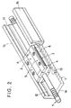
- Figures 1 and 2 illustrate a first embodiment of the linear guide device of the invention, which is basically formed of a track base or bed 1 having a substantially rectangular section opening at one side and fixed to, e.g., a bed, a substantially rectangular bearing block B (will be also called as a "block") engaging a screws shaft 7 of a feed screw mechanism for moving in a concave portion of the track bed 1, and a plurality of balls 2 or rolling members which bear loads between the block B and the track bed 1 during rolling therebetween.
- a substantially rectangular bearing block B (will be also called as a "block") engaging a screws shaft 7 of a feed screw mechanism for moving in a concave portion of the track bed 1, and a plurality of balls 2 or rolling members which bear loads between the block B and the track bed 1 during rolling therebetween.
- the block B is formed of, as shown in Figure 3, a block body 3 engaging the feed screw shaft 7, covers 4 attached to front and rear end surfaces of the block body 3, rolling aperture forming plates 4 engaging four corners of the block body 3, and a pair of ball retainers 6 engaging side surfaces of the block body 3.
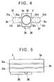
- the block body 3 includes, as shown in Figures 4-7, a ball-nut portion 3a engaging the screw shaft 7 and a pair of bearing portions 3b, and thus has a section similar to a cross.
- Each bearing portion 3a is provided at corners or edges with a pair of load ball grooves 31a and 31b, or 31c and 31d, in which the balls 2 rools.
- No-load ball grooves 32a-32d for circulating the balls which rolls from ends of the load ball grooves 31a-31d are formed at corners between the bearing portions 3b and the ball-nut portion 3a.
- Each bearing portion 3b is provided with tapped bolt apertures 37 into which attaching bolts 55 are screwed for attaching the rolling aperture forming plates 5.
- the ball-nut portion 3a engaging the screw shaft 7 is provided with, as shown in Figure 8, a through aperture 33 having a diameter slightly larger than the screw shaft 7 and a rolling groove 34 which is formed at a portion of the through aperture 33 and corresponds to a spiral ball rolling groove on the screw shaft 7. Further, a return tube 36 is fixed to the ball-nut portion 3a by a holder member 35 to form a circulation path. Pre-loads are applied to balls (not shown) disposed between the screw shaft 7 and the block body 3 for increasing accuracy of motion of the block B.
- the block body 3 thus constructed has a vertically and laterally symmetrical configuration, it can be manufactured by drawing without utilizing conventional machining such as cutting. Specifically, the block body 3 can be manufactured in such a manner that the drawing is applied to a steel member to form the above sectional shape and then polishing for the load ball grooves 31a-31d and drilling for the through apertures 33 are applied to it. According to this manufacturing method, block bodies 3 having intended lengths can be facilely manufactured by appropriately cutting the drawn steel member into pieces.
- the cover 4 has a sectional shape similar to a cross, as shown in Figures 9 and 10, and includes a base 4a and a pair of arms 4b projected therefrom.
- the cover 4 is formed by injection molding of synthetic resin.
- the base 4a is provided with a through aperture 41 into which the screw shaft 7 is inserted.
- Each projected arm 4b is provided at its opposite side surfaces with ball return grooves 42a-42d for connecting the load ball grooves 31a-31d on the block body 3 and the corresponding no-load ball grooves 32a-32d to each other (see Figure 11).
- a numeral 43 indicates one of projections for scooping and guiding the balls 2, which roll from the load ball grooves 31a-31d, into the ball return grooves 42a-42d.
- a numeral 44 indicates one of positioning seats for bearing the guide projections 53 which will be described later and are provided in the rolling aperture forming plates 5.
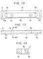
- the rolling aperture forming plates 5 are manufactured by injection molding of synthetic resin, similarly to the covers 4. As shown in Figures 12-14, the plates 5 each are provided at one surface with ball circulation grooves 51 corresponding to the no-load ball grooves 32a-32d on the block body 3 and the ball retrn grooves 42a-42d on the covers 4. Also, the plates 5 each are provided at one side edge with a ball retaining groove 52 which connects to the ball circulation groove 51 and corresponds to the load ball groove 31a-31d of the block body 3. Further, inside return portions 51a of the ball circulation paths 51, the guide pieces 53 are projected for positioning the plates 5 with respect to the block body 3 or the covers 4.
- each pair of the guide pieces 53 engage the front and rear end surfaces of the bearing portion 3b for positioning the block body 3, and rest on the positioning sheets 44 of the covers 4 for positioning the covers 4.
- Numerals 54 indicate penetrated apertures through which attaching bolts 55 are inserted for attaching the plates 5 to the block body 3.
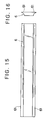
- the ball retainer 6 is a rod-like member having a nearly trapezoid shape, as shown in Figures 15 and 16, and has a width so determined that a gap between the projected end 61 of the retainer 6 attached to the block body 3 and the ball retaining groove 52 on the rolling aperture forming plate 5 may be smaller than the diameter of the ball 2, whereby the balls 2 are prevented from disengaging from the load ball grooves 31a-31d when the block B is removed from the track bed 1.
- the track bed 1 has a nearly rectangular shape opened at one side and includes a fixing portion 1a fixed to a basic member such as a bed, and a pair of support portions 1b projected from the opposite ends of the fixing portion 1a for supporting the block body 3.
- Each supporting portion 1b is provided at its inner surface with a groove 11, and the grooves 11 are provided at their upper and lower corners with ball rolling grooves 12a-12d opposed to the load ball grooves 31a-31d of the block body 3, respectively.
- a numeral 13 indicates one of blot holes into which fixing bolts for fixing the track bed 1 are inserted.
- the bearing block B is assembled by atttaching the covers 4 to the front and rear end surfaces of the block body 3 by screws (not shown), attching the four rolling aperture forming plates 5 to the bearing portions 3b of the block body 3 and attaching the ball retainers 6 to the side surfaces of the bearing portions 3b by screws (not shown).
- the no-load ball rolling apertures corresponding to the load ball grooves 31a-31d is formed of the no-load ball grooves 32a-32d on the block body 3 and the ball circulation grooves 51 on the rolling aperture forming plates 5 opposed thereto.
- the ball return paths which connect the no-load ball rolling apertures and the load ball grooves 31a-31d are formed of the ball return grooves 42a-42d on the covers 4 and the ball circulation grooves 51 on the plates 5 faced thereto.
- the no-load ball grooves 31a-31d are facilely formed by applying milling to the block body 3 and the ball return grooves 42a-42d and the ball circulation grooves 51 are facilely formed by the injection molding of the covers 4 and the rolling aperture forming plates 5, respectively. Therefore, even in the long block B, the no-load ball rolling apertures can be facilely and accurately formed.
- the balls 2 are covered with the plates or covers 4 mede from the synthetic resin while they are rolling the ball circulation paths, noises which may be caused by circulation of the balls can be reduced.
- the no-load rolling apertures can be facilely formed by machining the grooves for receiving the rolling members in the block body and/or the rolling aperture forming plates, so that the long bearing block can be facilely manufactured, and thus the number of the load rolling members can be increased to obtain the linear guide device having an increased maximum allowable load and a compact configuration.
- the block body having an intended length can be manufactured by cutting a drawn member, the productive efficiency can be increased and the costs can be reduced.
- the collision noises of the rolling members during rolling in the no-load apertures can be minimized, and thus the linear guide device having a small operation noise can be obtained.
Landscapes
- Engineering & Computer Science (AREA)
- General Engineering & Computer Science (AREA)
- Mechanical Engineering (AREA)
- Bearings For Parts Moving Linearly (AREA)
- Machine Tool Units (AREA)
Applications Claiming Priority (3)
| Application Number | Priority Date | Filing Date | Title |
|---|---|---|---|
| JP2130965A JPH076540B2 (ja) | 1990-05-21 | 1990-05-21 | 直線案内装置 |
| JP130965/90 | 1990-05-21 | ||
| PCT/JP1991/000646 WO1991018219A1 (fr) | 1990-05-21 | 1991-05-16 | Dispositif de guide rectiligne |
Publications (3)
| Publication Number | Publication Date |
|---|---|
| EP0483384A1 true EP0483384A1 (de) | 1992-05-06 |
| EP0483384A4 EP0483384A4 (en) | 1993-11-24 |
| EP0483384B1 EP0483384B1 (de) | 1997-08-13 |
Family
ID=15046765
Family Applications (1)
| Application Number | Title | Priority Date | Filing Date |
|---|---|---|---|
| EP91909372A Expired - Lifetime EP0483384B1 (de) | 1990-05-21 | 1991-05-16 | Linearlager |
Country Status (6)
| Country | Link |
|---|---|
| US (1) | US5277498A (de) |
| EP (1) | EP0483384B1 (de) |
| JP (1) | JPH076540B2 (de) |
| KR (1) | KR960000989B1 (de) |
| DE (1) | DE69127252T2 (de) |
| WO (1) | WO1991018219A1 (de) |
Cited By (4)
| Publication number | Priority date | Publication date | Assignee | Title |
|---|---|---|---|---|
| GB2247722B (en) * | 1990-08-27 | 1994-09-14 | Thk Co Ltd | Reciprocating device |
| EP0790421A1 (de) * | 1996-02-14 | 1997-08-20 | Neff Antriebstechnik Automation GmbH | Linearführung |
| EP0820834A1 (de) * | 1995-03-08 | 1998-01-28 | SMC Kabushiki Kaisha | Elektrisches Stellglied |
| US8016486B2 (en) * | 2004-08-27 | 2011-09-13 | Thk Co., Ltd. | Rolling guiding device |
Families Citing this family (18)
| Publication number | Priority date | Publication date | Assignee | Title |
|---|---|---|---|---|
| US5217308A (en) * | 1992-05-28 | 1993-06-08 | Robert Schroeder | Linear motion roller contact bearing assembly with bearing race inserts |
| DE4413373C2 (de) * | 1994-04-19 | 2001-05-17 | Schaeffler Waelzlager Ohg | Linearwälzlager |
| JP3412914B2 (ja) * | 1994-05-20 | 2003-06-03 | Thk株式会社 | 転がり案内装置および転がり案内装置の移動ブロックの製造方法 |
| JP3481771B2 (ja) * | 1996-04-25 | 2003-12-22 | Thk株式会社 | 直線案内装置のスライダの製造方法 |
| JPH09296821A (ja) * | 1996-05-07 | 1997-11-18 | Thk Kk | 直線案内装置のスライダの製造方法 |
| JP3919858B2 (ja) * | 1996-10-24 | 2007-05-30 | Thk株式会社 | 直線移動装置 |
| US6336393B1 (en) | 1998-07-01 | 2002-01-08 | Parker-Hannifin Corporation | Rodless pneumatic cylinder |
| JP3488686B2 (ja) * | 2000-12-05 | 2004-01-19 | Smc株式会社 | アクチュエータ |
| EP1215601A1 (de) * | 2000-12-15 | 2002-06-19 | Nsk Ltd | System zum Fördern des Einkaufens von Produkten |
| JP5031957B2 (ja) * | 2001-08-30 | 2012-09-26 | Thk株式会社 | リニアアクチュエータ |
| US20040066552A1 (en) * | 2002-06-18 | 2004-04-08 | Werba James A. | Low profile stage |
| US20050082954A1 (en) * | 2003-09-30 | 2005-04-21 | Dunbar Lee R. | Removable toe kick floor for cupboards vanities cabinets |
| DE202006006447U1 (de) * | 2006-04-21 | 2006-07-13 | Festo Ag & Co. | Fluidbetätigte Linearantriebsvorrichtung |
| JP5343513B2 (ja) * | 2008-11-04 | 2013-11-13 | 日本精工株式会社 | 直動装置 |
| TWI421416B (zh) * | 2009-10-30 | 2014-01-01 | Ind Tech Res Inst | 線性滑台 |
| KR101583427B1 (ko) * | 2014-08-21 | 2016-01-07 | 이동석 | 리니어 가이드 |
| CN106122690B (zh) * | 2016-06-28 | 2018-06-22 | 上海锅炉厂有限公司 | 一种轴承滚轮式横向位移托板 |
| CN108970919B (zh) * | 2018-07-20 | 2020-08-04 | 嘉兴乐之源光伏科技有限公司 | 一种移动式涂胶装置 |
Family Cites Families (13)
| Publication number | Priority date | Publication date | Assignee | Title |
|---|---|---|---|---|
| JPS5834225A (ja) * | 1981-08-25 | 1983-02-28 | Hiroshi Teramachi | リニヤボ−ルベアリングユニツト |
| JPS6084421A (ja) * | 1983-10-14 | 1985-05-13 | Ichiro Katayama | 摺動台装置用ベアリングユニツト |
| JPS6192317A (ja) * | 1984-10-11 | 1986-05-10 | Tsubakimoto Seikou:Kk | 直線運動用ボ−ルベアリング |
| JPS61206818A (ja) * | 1985-03-08 | 1986-09-13 | Hiroshi Teramachi | 直線運動用ベアリングユニツト |
| JPH0623569B2 (ja) * | 1985-07-15 | 1994-03-30 | 松下電器産業株式会社 | 移動テーブル |
| JPS62200016A (ja) * | 1986-02-28 | 1987-09-03 | Tsubakimoto Seiko:Kk | ボ−ルねじ内蔵の直線運動用ボ−ルベアリング |
| JPS637243A (ja) * | 1986-06-26 | 1988-01-13 | Sabun Kogyosho:Kk | ボ−ルスライドウエイ |
| JPH0164339U (de) * | 1987-10-16 | 1989-04-25 | ||
| FR2642123B1 (fr) * | 1989-01-25 | 1991-05-10 | Lecomte Marc | Guide lineaire de precision |
| JP2811748B2 (ja) * | 1989-05-17 | 1998-10-15 | 日本精工株式会社 | フィードユニット装置 |
| JPH03213714A (ja) * | 1990-01-17 | 1991-09-19 | Nippon Thompson Co Ltd | 樹脂製直動案内ユニット |
| DE4005582C2 (de) * | 1990-02-22 | 1996-01-25 | Neff Antriebstech Automation | Linearlager und Herstellungsverfahren für dessen Kugelumleitungseinrichtungen |
| JP2582490B2 (ja) * | 1991-08-22 | 1997-02-19 | コナミ株式会社 | 電光式標的殴打遊戯機の標的構造 |
-
1990
- 1990-05-21 JP JP2130965A patent/JPH076540B2/ja not_active Expired - Fee Related
-
1991
- 1991-05-16 KR KR1019910702022A patent/KR960000989B1/ko not_active Expired - Lifetime
- 1991-05-16 EP EP91909372A patent/EP0483384B1/de not_active Expired - Lifetime
- 1991-05-16 DE DE69127252T patent/DE69127252T2/de not_active Expired - Fee Related
- 1991-05-16 WO PCT/JP1991/000646 patent/WO1991018219A1/ja not_active Ceased
- 1991-05-16 US US07/809,508 patent/US5277498A/en not_active Expired - Lifetime
Non-Patent Citations (1)
| Title |
|---|
| See references of WO9118219A1 * |
Cited By (6)
| Publication number | Priority date | Publication date | Assignee | Title |
|---|---|---|---|---|
| GB2247722B (en) * | 1990-08-27 | 1994-09-14 | Thk Co Ltd | Reciprocating device |
| EP0820834A1 (de) * | 1995-03-08 | 1998-01-28 | SMC Kabushiki Kaisha | Elektrisches Stellglied |
| US5747896A (en) * | 1995-03-08 | 1998-05-05 | Smc Kabushiki Kaisha | Electric actuator |
| EP0790421A1 (de) * | 1996-02-14 | 1997-08-20 | Neff Antriebstechnik Automation GmbH | Linearführung |
| US5806986A (en) * | 1996-02-14 | 1998-09-15 | Neff Antriebstechnik Automation Gmbh | Tubular linear guide system with internally positioned guided body |
| US8016486B2 (en) * | 2004-08-27 | 2011-09-13 | Thk Co., Ltd. | Rolling guiding device |
Also Published As
| Publication number | Publication date |
|---|---|
| DE69127252D1 (en) | 1997-09-18 |
| JPH0425618A (ja) | 1992-01-29 |
| DE69127252T2 (de) | 1998-02-19 |
| KR920702760A (ko) | 1992-10-06 |
| EP0483384A4 (en) | 1993-11-24 |
| KR960000989B1 (ko) | 1996-01-15 |
| WO1991018219A1 (fr) | 1991-11-28 |
| JPH076540B2 (ja) | 1995-01-30 |
| US5277498A (en) | 1994-01-11 |
| EP0483384B1 (de) | 1997-08-13 |
Similar Documents
| Publication | Publication Date | Title |
|---|---|---|
| EP0483384A1 (de) | Linearlager | |
| US4417771A (en) | Linear ball bearing unit | |
| US4988215A (en) | Linear guide apparatus using a combination of balls and rollers | |
| JPS6343607B2 (de) | ||
| EP1413784B1 (de) | Linearbewegungs- Führungskugellager und Verfahren zur Herstellung | |
| US4932279A (en) | Feed screw apparatus | |
| US4472003A (en) | Track guide bearing assembly | |
| EP0489165A1 (de) | Tisch für linearführung | |
| US6210040B1 (en) | Linear-movement guide | |
| JPH0232488B2 (de) | ||
| KR870000389B1 (ko) | 직선 슬라이드 베어링과 직선 슬라이드 테이블 유닛 | |
| KR860001684B1 (ko) | 무한직선운동용 굴림대 축받이 | |
| US7296930B2 (en) | Rolling guide device and manufacturing method thereof, and driving device including the rolling guide device | |
| JPS5848773B2 (ja) | リニヤボ−ルベアリングユニツト | |
| JPH08320019A (ja) | 軽量型リニアガイド装置 | |
| JPH0620894Y2 (ja) | 軽量型リニアガイド装置 | |
| KR900001631B1 (ko) | 직선 슬라이드용 보올 베어링 | |
| US5490729A (en) | Ball spline | |
| JPS6211207B2 (de) | ||
| JPS628426Y2 (de) | ||
| JPS628425Y2 (de) | ||
| JP3587086B2 (ja) | 送りねじ付き直線運動案内装置 | |
| JP3587087B2 (ja) | 送りねじ付き直線運動案内装置 | |
| KR860001718B1 (ko) | 직선 접동 베어링 | |
| JPS6224653B2 (de) |
Legal Events
| Date | Code | Title | Description |
|---|---|---|---|
| PUAI | Public reference made under article 153(3) epc to a published international application that has entered the european phase |
Free format text: ORIGINAL CODE: 0009012 |
|
| AK | Designated contracting states |
Kind code of ref document: A1 Designated state(s): DE FR GB IT |
|
| 17P | Request for examination filed |
Effective date: 19920518 |
|
| A4 | Supplementary search report drawn up and despatched |
Effective date: 19931007 |
|
| AK | Designated contracting states |
Kind code of ref document: A4 Designated state(s): DE FR GB IT |
|
| 17Q | First examination report despatched |
Effective date: 19940714 |
|
| GRAG | Despatch of communication of intention to grant |
Free format text: ORIGINAL CODE: EPIDOS AGRA |
|
| GRAH | Despatch of communication of intention to grant a patent |
Free format text: ORIGINAL CODE: EPIDOS IGRA |
|
| GRAH | Despatch of communication of intention to grant a patent |
Free format text: ORIGINAL CODE: EPIDOS IGRA |
|
| GRAA | (expected) grant |
Free format text: ORIGINAL CODE: 0009210 |
|
| AK | Designated contracting states |
Kind code of ref document: B1 Designated state(s): DE FR GB IT |
|
| REF | Corresponds to: |
Ref document number: 69127252 Country of ref document: DE Date of ref document: 19970918 |
|
| ITF | It: translation for a ep patent filed | ||
| ET | Fr: translation filed | ||
| PLBE | No opposition filed within time limit |
Free format text: ORIGINAL CODE: 0009261 |
|
| STAA | Information on the status of an ep patent application or granted ep patent |
Free format text: STATUS: NO OPPOSITION FILED WITHIN TIME LIMIT |
|
| 26N | No opposition filed | ||
| PGFP | Annual fee paid to national office [announced via postgrant information from national office to epo] |
Ref country code: GB Payment date: 20010516 Year of fee payment: 11 |
|
| REG | Reference to a national code |
Ref country code: GB Ref legal event code: IF02 |
|
| PGFP | Annual fee paid to national office [announced via postgrant information from national office to epo] |
Ref country code: FR Payment date: 20020508 Year of fee payment: 12 |
|
| PG25 | Lapsed in a contracting state [announced via postgrant information from national office to epo] |
Ref country code: GB Free format text: LAPSE BECAUSE OF NON-PAYMENT OF DUE FEES Effective date: 20020516 |
|
| GBPC | Gb: european patent ceased through non-payment of renewal fee |
Effective date: 20020516 |
|
| PG25 | Lapsed in a contracting state [announced via postgrant information from national office to epo] |
Ref country code: FR Free format text: LAPSE BECAUSE OF NON-PAYMENT OF DUE FEES Effective date: 20040130 |
|
| REG | Reference to a national code |
Ref country code: FR Ref legal event code: ST |
|
| PG25 | Lapsed in a contracting state [announced via postgrant information from national office to epo] |
Ref country code: IT Free format text: LAPSE BECAUSE OF NON-PAYMENT OF DUE FEES;WARNING: LAPSES OF ITALIAN PATENTS WITH EFFECTIVE DATE BEFORE 2007 MAY HAVE OCCURRED AT ANY TIME BEFORE 2007. THE CORRECT EFFECTIVE DATE MAY BE DIFFERENT FROM THE ONE RECORDED. Effective date: 20050516 |
|
| PGFP | Annual fee paid to national office [announced via postgrant information from national office to epo] |
Ref country code: DE Payment date: 20070510 Year of fee payment: 17 |
|
| PG25 | Lapsed in a contracting state [announced via postgrant information from national office to epo] |
Ref country code: DE Free format text: LAPSE BECAUSE OF NON-PAYMENT OF DUE FEES Effective date: 20081202 |