EP0479499A1 - Steuerungsverfahren und -Vorrichtung für Webmaschinen - Google Patents
Steuerungsverfahren und -Vorrichtung für Webmaschinen Download PDFInfo
- Publication number
- EP0479499A1 EP0479499A1 EP91308845A EP91308845A EP0479499A1 EP 0479499 A1 EP0479499 A1 EP 0479499A1 EP 91308845 A EP91308845 A EP 91308845A EP 91308845 A EP91308845 A EP 91308845A EP 0479499 A1 EP0479499 A1 EP 0479499A1
- Authority
- EP
- European Patent Office
- Prior art keywords
- loom
- woven fabric
- temple
- support plate
- attached
- Prior art date
- Legal status (The legal status is an assumption and is not a legal conclusion. Google has not performed a legal analysis and makes no representation as to the accuracy of the status listed.)
- Withdrawn
Links
Images


Classifications
-
- D—TEXTILES; PAPER
- D03—WEAVING
- D03J—AUXILIARY WEAVING APPARATUS; WEAVERS' TOOLS; SHUTTLES
- D03J1/00—Auxiliary apparatus combined with or associated with looms
- D03J1/22—Temples
Definitions
- the present invention relates generally to air jet looms and, more particularly, to a system for automatically controlling an air jet loom used for weaving cloth having more than one pick range, such as tire-cord fabric.
- Tire-cord fabric includes a body portion having between 1 and 3.5 picks per inch (ppi) and a tab portion at each end of the body portion having between 3.5 and 50 ppi.
- the tab portion is used to stabilize the ends of the body portion of the cloth and to permit separation of the cloth into smaller batches. Because of the differences in pick density between the body portion and tab portions, it is necessary that temples be inserted to stretch the fabric when the tab portion is woven to keep the fabric at its correct width. Conventional temples are set at the fell of the cloth so that the warp and the filling in the weaving will interface at right angles to form the proper fabric width.
- Temples of this type can be set very close to the fell of the cloth because of their small cross-section and because they extend over the entire weaving width and they favor a uniform interlacing of the filling yarn.
- U. S. Patent 3,943,979 provides an improvement over the "Lupton" temples in a construction which is effective to improve the stretching effect of such temples.
- the ends of the cylindrical rod are designed as tubular portions having a plurality of circumferentially spaced longitudinal keyways which extend through the wall of the tubular portion.
- Longitudinal keys are provided in the keyways with needle points which project at least approximately radially to the outside and are placed and guided in each of the keyways for the positive longitudinal displacement.
- the longitudinal motion of the keys is obtained by guiding their end portions in an oblique annular grove which is provided in a guide body connected to the hollow bar and secured in a stationary position against rotation.
- a radial piercing of the selvage zone by the needle points during rotation of the rod to produce an anchorage of the web to the keys is obtained by providing a bolt which extends parallel to, and eccentrically of, the rod in each of the tubular end portions of the rod and is fixed in the guide body.
- the bolt extends through a bore of the guide body in which it is fixed, and the longitudinal keys bear against its circumferential surface.
- the rod is mounted for turning eccentrically relatively to the bolt so that, with its continuous turning, the longitudinally displaceable keys are moved with their needle points into and out of the longitudinal keyways over at least a part of the peripheral ranges which are enveloped by the web.
- these temples can not be automatically inserted and removed.
- U.S. Patent No. 3,943,978 issued to Jindra, discloses a method and apparatus for lateral tensioning or holding knitted fabrics at a predetermined width. A portion of the fabric adjacent to the edge is formed having uncovered weft threads. The uncovered weft threads are engaged and deflected from above and below by means of a lever which penetrates between the uncovered weft threads so that the strip bears against the side of the which acts as a temple. However, the temple device is continuously in engagement with the fabric and can not be automatically inserted and removed.
- temples with a good stretching effect
- spike-disc temple which is equipped with needle points which are manually actuated to stick into the selvage.
- Such temples are bulky so that they cannot be mounted close to the fell of the cloth, as is the case with the known "Lupton” temples, however, they may be easily engaged and disengaged by hand through use of a wrench.
- an automatic temple insertion device for use with a new and improved air jet loom control system which is operable to insert multiple tabs on a roll for separating multiple body portions of the roll, providing an inspection segment per roll, and/or providing a cut line either by "no picks" or by changing the filling used within the tab.
- the present invention is directed to a system for controlling an air jet loom and, in particular, for controlling a loom used for weaving cloth having move than one pick range, such as for cloth used for tire-cord fabric.
- Tire-cord fabric includes a body portion having between 1 and 3.5 ppi and a least one tab portion having between 3.5 and 50 ppi. The tab portions are used to stabilize the ends of the body portion of the cloth and to permit separation of the cloth into smaller batches.
- the control system includes an automatic temple insertion device.
- the system further includes dual nozzles to automatically switch from tab to body; automatic pick spacing change from tab to body; and an automatic dual warp yarn tension level control.
- the system permits multiple tabs on a roll for separating multiple body portions of the roll, providing an inspection segment per roll, and/or providing a cut line either by "no picks" or by changing the filling within the tab.
- the automatic temple insertion device includes a bi-stable linkage which is attached to an air cylinder and is operable to move the temple from a first inoperable position to a second operable position whereby the temple contacts the fabric.
- the automatic temple insertion device in combination with the dual nozzles and automatic pick spacing and warp yarn tension change, permits an operator to preprogram an entire creel and have the loom operate without further operator intervention.
- one aspect of the present invention is to provide an apparatus for a power loom for automatically varying the pick density of a woven fabric produced by the loom between a first density value to a second, substantially different density value.
- the apparatus includes: means associated with the loom for supplying a fill yarn suitable for forming the portion of the woven fabric corresponding to the first density value; means associated with the loom for adjusting the pick density of the woven fabric; temple means for holding the woven fabric at a predetermined width, the temple means being selectively operable between a first position out of engagement with the woven fabric and a second position in engagement with the woven fabric; and control means connected to the first and second means for supplying fill yarn, the means associated with the loom, and the temple means, the control means being operable to selectively engage the temple means and permit the loom to vary the pick density of the woven fabric while maintaining the woven fabric at a predetermined width without operator intervention.
- Another aspect of the present invention is to provide an apparatus for automatically inserting a temple for holding woven fabric in a loom at a predetermined width.
- the apparatus includes: a support plate attached to one side of the loom adjacent to the edge of the woven fabric; a bracket pivotally attached at one end to the support plate and attached to the temple at the other end; and actuator means attached at one end to the support plate and at the other end to the bracket, whereby the temple is selectively operable between a first position out of engagement with the woven fabric and a second position in engagement with the woven fabric.
- Still another aspect of the present invention is to provide a weaving apparatus for automatically forming intermediate tabby sections in a continuous length of woven fabric on a power loom.
- the apparatus includes: first means associated with the loom for supplying a fill yarn having a first predetermined denier value; second means associated with the loom for supplying a fill yarn having a second predetermined denier value; take-up roll means associated with the loom for adjusting the pick density of the woven fabric; temple means for holding the woven fabric at a predetermined width, the temple means including (i) a support plate attached to one side of the loom adjacent to the edge of the woven fabric; (ii) a bracket pivotally attached at one end to the support plate and attached to the temple at the other end; and (iii) actuator means attached at one end to the support plate and at the other end to the bracket, the temple means being selectively operable between a first position out of engagement with the woven fabric and a second position in engagement with the woven fabric; and control means connected to the first and second means
- FIG. 1 an air jet loom for weaving tire-cord fabric, generally designated 10, is shown constructed according to the present invention.
- an entire creel may provide enough yarn to weave approximately 12,000 yards of tire cord fabric.
- the Air Jet Tire Cord Weaving System 10 receives yarn supply 12 from a conventional warp creel (not shown). The ends of the yarn pass through an eye board 14 and through a constant tension compensator 16.
- a constant tension compensator 16 is shown in U.S. patent no. 4,216,804, issued to Alexander et al., the entire disclosure of which is hereby incorporated by reference.
- the air jet weaving machine 20 is a conventional design.
- One machine which is particularly suitable for use in this system is a model J-4400 air jet weaving machine constructed by Draper Corporation, Greensboro, North Carolina.
- the loom control system 10 includes duel feeders 34 and duel air jets 36. Each of these components are connected to a programmable logic controller (PLC) 40.
- PLC programmable logic controller
- controller 40 which has been particularly suitable an Omron Model S6 with two relay output modules.
- a selvage detector 42 and filling detector 44 also may be connected to the loom 20. Filling detectors are in themselves conventional and well known to the prior art.
- the selvage detector 42 operates by detecting the presence of the spread out of the woven fabric which occurs due to a tucking failure.
- the compressor 16 provides a control signal 46 representative of the amount of yardage passing through the loom 20.
- the take-up roll 30 provide a control signal 50 representative of motor speed to PLC 40.
- feedback circuit 52 from the PLC 40 alerts the take-up roll 30 that the motor speed is correct.
- a feedback circuit 54 from the PLC 40 informs the air jet loom 20 when the correct speed is reached.
- the PLC 40 provides an on/off control signal to automatic temple actuators 22 and 24 located on opposite sides of the air jet loom 10.
- the PLC 40 also provides a signal 60 equal to the desired tension to the warp yarn to compressor 16.
- Yarn supply 12 may include a stop motion signal 61 to controller to halt its operation.
- selvage detector 41 and filling detector 44 may also provide stop motion detection signals 64, 66, respectively, for the same purpose.
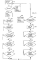
- the yardage of each of the cloth lengths 70 is first entered in the PLC 40.
- the PLC 40 compares this value with the yardage measurement 46 received from compressor 16 and a predetermined value to determine whether the tabby should be inserted or not. If not necessary, PLC 40 provides a stop loom signal to the operator 74. Otherwise, the controller 40 compares the value of the tabby to the value set for the tabby length 76.
- the PLC 40 provides control signals which engage the temples 80; changes the feeders 81; changes the relay nozzle pressure 84; changes the main nozzle pressure 86; changes pick spacings 90; changes the warp tension 91; changes the air value timing 94; and changes the feeder firing position 96 to that of the higher density woven cloth for the tabby.
- the PLC 40 then monitors the yardage value 46 to determine when the end of the tabby 100 has been reached and decides 101 whether this an intermediate tabby or a final tabby. If it is a final tabby, the PLC 40 provides a signal 104 to stop the loom and signal the operator. If it is an intermediate tabby, the PLC 40 proceeds to the second yardage value 70 back to the beginning of the flow chart.
- temple insert device 110 includes a lever arm 112 which is attached to the temple support bracket 114.
- Lever arm 112 is pivotable about pivot point 116 from the engaged position to a disengaged position.
- the end of lever arm 112 opposite from temple bracket 114 may be provided with a stop 118 to ensure proper positioning of the manual trip temple insertion device.
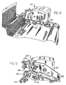
- an automatic temple actuator 120 constructed according to the present invention.
- the automatic temple actuator 120 includes a mounting base 122 which may be attached to the existing selvage tucker of the air jet loom.
- a two way air cylinder 124 is attached at one end to the mounting base 122 and at the other end to a bi-stable lever arm 128.
- One end of the bi-stable lever arm 128 is attached to the mounting base 122 and the other end is attached by means of a bearing 130 to the existing lever arm 112 adjacent to the temple bracket 114.
- a pair of adjustable stops 132, 134 are attached to the mounting base 122 on either side of the bi-stable lever 128.
- Figure 6 illustrates a side elevational view of the automatic temple insertion device, shown in Figure 5, in its engaged position.
- the plunger of cylinder 124 extends causing bistable lever 128 to move forward and engage adjustable stop 134.
- This action increases the effective length of the bi-stable lever 128, thereby depressing lever arm 112 and causing temple bracket 114 to be lowered and engage the fabric.
- bi-stable lever 128 returns against adjustable stop 132 causing the effective length of lever arm of 128 to be shortened, thereby raising lever arm 112 to disengage the temple.
- Any of a number of conventional air cylinders can be used for the present invention, however a Clippard model UDR-17-15, manufactured by Clippard Manufacturing of Cincinnati, Ohio and having a 3-inch stroke and operated at 90 PSI has been found particularly suitable.
Applications Claiming Priority (2)
| Application Number | Priority Date | Filing Date | Title |
|---|---|---|---|
| US07/591,774 US5065796A (en) | 1990-10-02 | 1990-10-02 | Loom temple control system to vary pick density |
| US591774 | 1990-10-02 |
Publications (1)
| Publication Number | Publication Date |
|---|---|
| EP0479499A1 true EP0479499A1 (de) | 1992-04-08 |
Family
ID=24367881
Family Applications (1)
| Application Number | Title | Priority Date | Filing Date |
|---|---|---|---|
| EP91308845A Withdrawn EP0479499A1 (de) | 1990-10-02 | 1991-09-27 | Steuerungsverfahren und -Vorrichtung für Webmaschinen |
Country Status (6)
| Country | Link |
|---|---|
| US (1) | US5065796A (de) |
| EP (1) | EP0479499A1 (de) |
| JP (1) | JPH04281041A (de) |
| KR (1) | KR920008240A (de) |
| CS (1) | CS295991A3 (de) |
| DE (1) | DE4132696C2 (de) |
Cited By (2)
| Publication number | Priority date | Publication date | Assignee | Title |
|---|---|---|---|---|
| CN103194845A (zh) * | 2013-05-03 | 2013-07-10 | 山东丝绸纺织职业学院 | 经向服装平织机织制方法 |
| CN103194844A (zh) * | 2013-04-12 | 2013-07-10 | 山东丝绸纺织职业学院 | 纬向服装平织机织制方法 |
Families Citing this family (5)
| Publication number | Priority date | Publication date | Assignee | Title |
|---|---|---|---|---|
| US5372164A (en) * | 1993-12-23 | 1994-12-13 | Bridgestone/Firestone, Inc. | Quick change assembly for tire cord fabric looms |
| US7413779B2 (en) * | 2004-08-25 | 2008-08-19 | Hyosung Usa, Inc. | Tire fabric treating unit |
| JP5564329B2 (ja) * | 2010-05-21 | 2014-07-30 | 津田駒工業株式会社 | テンプル位置自動切換機構を有するテンプル装置を備えた織機における送出制御方法及び装置 |
| JP5520717B2 (ja) * | 2010-07-06 | 2014-06-11 | 津田駒工業株式会社 | テンプル位置自動切換機構を有する織機のテンプル装置及びそのテンプルの駆動方法 |
| JP5651392B2 (ja) * | 2010-07-06 | 2015-01-14 | 津田駒工業株式会社 | テンプル位置自動切換機構を有する織機のテンプル装置及びそのテンプルの駆動方法 |
Citations (6)
| Publication number | Priority date | Publication date | Assignee | Title |
|---|---|---|---|---|
| FR845984A (fr) * | 1938-11-15 | 1939-09-06 | Perfectionnement aux templets pour maintenir la largeur du tissu | |
| DE2825537A1 (de) * | 1978-06-10 | 1979-12-20 | Olbo Textilwerke Gmbh | Gewebebahn |
| FR2520012A1 (fr) * | 1982-01-20 | 1983-07-22 | Gagey Etienne | Dispositif pour commander le deroulement des fils de chaine et l'enroulement du tissu sur une machine a tisser |
| DE3520244A1 (de) * | 1984-08-24 | 1986-03-06 | Aktiengesellschaft Adolph Saurer, Arbon | Warenabzugseinrichtung an einer webmaschine |
| EP0376338A2 (de) * | 1988-12-28 | 1990-07-04 | Kabushiki Kaisha Toyota Chuo Kenkyusho | Keltzuführkontrolleinrichtung für eine Webmaschine |
| DE9006343U1 (de) * | 1989-06-23 | 1990-09-20 | Gebrueder Sulzer Ag, Winterthur, Ch |
Family Cites Families (13)
| Publication number | Priority date | Publication date | Assignee | Title |
|---|---|---|---|---|
| US3525367A (en) * | 1969-01-06 | 1970-08-25 | North American Rockwell | Loom tension control apparatus |
| CS171369B1 (de) * | 1972-08-16 | 1976-10-29 | ||
| CH570488A5 (de) * | 1974-01-25 | 1975-12-15 | Saurer Ag Adolph | |
| US4048004A (en) * | 1976-03-29 | 1977-09-13 | Eastman Kodak Company | Apparatus for moving a tool into and out of engagement with a workpiece |
| US4203563A (en) * | 1978-10-02 | 1980-05-20 | Alexander-Cooper, Inc. | Loom take-up cloth roll doffer |
| US4216804A (en) * | 1978-10-02 | 1980-08-12 | Alexander-Cooper, Inc. | Loom cloth tension control |
| JPS60181349A (ja) * | 1984-02-24 | 1985-09-17 | 津田駒工業株式会社 | 織機の巻取り制御装置 |
| DE3530119A1 (de) * | 1985-08-23 | 1987-02-26 | Bernd Dipl Ing Scheffel | Vorrichtung fuer webmaschinen und verfahren zu deren betrieb |
| US4910837A (en) * | 1986-03-17 | 1990-03-27 | Kabushiki Kaisha Toyoda Jidoshokki Seisakusho | Looming apparatus for a loom |
| DE3609845A1 (de) * | 1986-03-22 | 1987-09-24 | Stromag Maschf | Verfahren und vorrichtung zur musterbildung bei einer webmaschine |
| DD261383A1 (de) * | 1987-05-26 | 1988-10-26 | Fuerstenwalde Reifen Veb K | Vorrichtung zur herstellung von reifenkordgewebe |
| DE3818766A1 (de) * | 1988-06-02 | 1989-12-07 | Dornier Gmbh Lindauer | Duesensteuerung fuer einen luftwebstuhl |
| BE1002819A3 (nl) * | 1989-02-06 | 1991-06-18 | Picanol Nv | Werkwijze voor het weven van een weefsel met een weefselpatroon, en weefmachines die deze werkwijze toepassen. |
-
1990
- 1990-10-02 US US07/591,774 patent/US5065796A/en not_active Expired - Fee Related
-
1991
- 1991-09-27 CS CS912959A patent/CS295991A3/cs unknown
- 1991-09-27 EP EP91308845A patent/EP0479499A1/de not_active Withdrawn
- 1991-10-01 JP JP3282081A patent/JPH04281041A/ja active Pending
- 1991-10-01 KR KR1019910017205A patent/KR920008240A/ko not_active Application Discontinuation
- 1991-10-01 DE DE4132696A patent/DE4132696C2/de not_active Expired - Fee Related
Patent Citations (6)
| Publication number | Priority date | Publication date | Assignee | Title |
|---|---|---|---|---|
| FR845984A (fr) * | 1938-11-15 | 1939-09-06 | Perfectionnement aux templets pour maintenir la largeur du tissu | |
| DE2825537A1 (de) * | 1978-06-10 | 1979-12-20 | Olbo Textilwerke Gmbh | Gewebebahn |
| FR2520012A1 (fr) * | 1982-01-20 | 1983-07-22 | Gagey Etienne | Dispositif pour commander le deroulement des fils de chaine et l'enroulement du tissu sur une machine a tisser |
| DE3520244A1 (de) * | 1984-08-24 | 1986-03-06 | Aktiengesellschaft Adolph Saurer, Arbon | Warenabzugseinrichtung an einer webmaschine |
| EP0376338A2 (de) * | 1988-12-28 | 1990-07-04 | Kabushiki Kaisha Toyota Chuo Kenkyusho | Keltzuführkontrolleinrichtung für eine Webmaschine |
| DE9006343U1 (de) * | 1989-06-23 | 1990-09-20 | Gebrueder Sulzer Ag, Winterthur, Ch |
Cited By (2)
| Publication number | Priority date | Publication date | Assignee | Title |
|---|---|---|---|---|
| CN103194844A (zh) * | 2013-04-12 | 2013-07-10 | 山东丝绸纺织职业学院 | 纬向服装平织机织制方法 |
| CN103194845A (zh) * | 2013-05-03 | 2013-07-10 | 山东丝绸纺织职业学院 | 经向服装平织机织制方法 |
Also Published As
| Publication number | Publication date |
|---|---|
| DE4132696A1 (de) | 1992-04-09 |
| JPH04281041A (ja) | 1992-10-06 |
| KR920008240A (ko) | 1992-05-27 |
| US5065796A (en) | 1991-11-19 |
| DE4132696C2 (de) | 1995-10-26 |
| CS295991A3 (en) | 1992-05-13 |
Similar Documents
| Publication | Publication Date | Title |
|---|---|---|
| EP0164773B1 (de) | Verstellbare Steuerung des Schussfadens in Webmaschinen | |
| US6575201B2 (en) | Fabric with a variable width | |
| US4502512A (en) | Method for treating a weft yarn upon stoppage of a shuttleless loom and device for effecting the same | |
| US5065796A (en) | Loom temple control system to vary pick density | |
| US4949759A (en) | Seersucker loom with tension regulation of puckering warp | |
| EP0257857A2 (de) | Kontrollvorrichtung für das Verhältnis des Plüschhenkelns | |
| EP0236601B1 (de) | Automatische Maschine zum Verbinden zweier Enden eines Bandes | |
| EP0397443B1 (de) | Verfahren und Vorrichtung zur Garnzuführkontrolle | |
| EP0461524B2 (de) | Schussfadenzubringvorrichtung für Greiferwebmaschinen | |
| US7073399B2 (en) | Yarn processing system | |
| US4410017A (en) | Method and apparatus for pneumatic insertion of a weft thread in the shuttle of a multi-feed weaving loom | |
| JPH09209243A (ja) | 織機の開口に通すべきよこ糸の荷重低減装置 | |
| US20010054450A1 (en) | Terry loom with pile warp length compensation and deflection into back shed | |
| EP1266056B1 (de) | Verfahren zum eintragen eines elastomer-fadens und fadenverarbeitungssystem | |
| US6367511B2 (en) | Terry loom with interpenetrating ground warp and pile warp | |
| JPS633986B2 (de) | ||
| US5018557A (en) | Weft-switching system with telescoping nozzles | |
| EP0333262A1 (de) | Luftstrahlwebmaschine mit verbessertem Schussfadeneintrag | |
| KR920006958B1 (ko) | 젯트 직기에 있어서 제직조건 설정방법 | |
| US4825911A (en) | Patterned woven fabric | |
| CA1318830C (en) | Method of manufacturing an insertion-type seam for making a cloth belt endless, and seaming machine | |
| EP1033427B1 (de) | Verstellbare Gewebestütze für Webmaschinen | |
| EP0561218A1 (de) | Verfahren und Vorrichtung zur Bereitstellung einer definierten Schussfadenreserve bei Webstop | |
| JPH043027Y2 (de) | ||
| GB1576726A (en) | Selvedges in woven fabrics |
Legal Events
| Date | Code | Title | Description |
|---|---|---|---|
| PUAI | Public reference made under article 153(3) epc to a published international application that has entered the european phase |
Free format text: ORIGINAL CODE: 0009012 |
|
| AK | Designated contracting states |
Kind code of ref document: A1 Designated state(s): BE CH DE IT LI |
|
| 17P | Request for examination filed |
Effective date: 19920916 |
|
| 17Q | First examination report despatched |
Effective date: 19940516 |
|
| GRAG | Despatch of communication of intention to grant |
Free format text: ORIGINAL CODE: EPIDOS AGRA |
|
| GRAH | Despatch of communication of intention to grant a patent |
Free format text: ORIGINAL CODE: EPIDOS IGRA |
|
| STAA | Information on the status of an ep patent application or granted ep patent |
Free format text: STATUS: THE APPLICATION IS DEEMED TO BE WITHDRAWN |
|
| 18D | Application deemed to be withdrawn |
Effective date: 19970428 |