EP0478801B1 - Michelson interferometer - Google Patents
Michelson interferometer Download PDFInfo
- Publication number
- EP0478801B1 EP0478801B1 EP91908474A EP91908474A EP0478801B1 EP 0478801 B1 EP0478801 B1 EP 0478801B1 EP 91908474 A EP91908474 A EP 91908474A EP 91908474 A EP91908474 A EP 91908474A EP 0478801 B1 EP0478801 B1 EP 0478801B1
- Authority
- EP
- European Patent Office
- Prior art keywords
- signal
- movable reflector
- light
- beam splitter
- feedback signal
- Prior art date
- Legal status (The legal status is an assumption and is not a legal conclusion. Google has not performed a legal analysis and makes no representation as to the accuracy of the status listed.)
- Expired - Lifetime
Links
Images


Classifications
-
- G—PHYSICS
- G01—MEASURING; TESTING
- G01J—MEASUREMENT OF INTENSITY, VELOCITY, SPECTRAL CONTENT, POLARISATION, PHASE OR PULSE CHARACTERISTICS OF INFRARED, VISIBLE OR ULTRAVIOLET LIGHT; COLORIMETRY; RADIATION PYROMETRY
- G01J3/00—Spectrometry; Spectrophotometry; Monochromators; Measuring colours
- G01J3/28—Investigating the spectrum
- G01J3/45—Interferometric spectrometry
- G01J3/453—Interferometric spectrometry by correlation of the amplitudes
- G01J3/4535—Devices with moving mirror
Definitions
- the present invention relates to a Michelson interferometer which is used, for example, in an optical spectrum analyzer, for generating interference light of a frequency corresponding to the wavelength of light to be measured and, more particularly, to a moving reflector driving part of the Michelson interferometer.
- Fig. 1 shows a conventional Michelson interferometer.
- Light to be measured 11 is incident to a beam splitter 12 such as a semitransparent mirror, by which it is split into reflected light and transmitted light at a 1:1 power rate, and the reflected light is incident to a fixed reflector 13.
- the fixed reflector 13 is a reflector which reflects the incident light back to its incoming direction, such as a mirror or corner-cube prism.
- the transmitted light through the beam splitter 12 is incident to a movable reflector 14.
- the movable reflector 14 is also to reflect the incident light back to its incoming direction as is the case with the fixed reflector 13.
- the reflected light from the fixed reflector 13 and the reflected light from the movable reflector 14 return to the beam splitter 12, wherein they are combined and interfere with each other, and the resulting interference light is received by a photodetector (15) and converted into an electric signal.
- the movable reflector 14 mounted on a linear motor 16 moves toward and away from the beam splitter 12.
- Its detected output is a pair of two-phase pulse signals D1 and D2 displaced 90° apart in phase (phase shifted by 90°) from each other and the direction of movement of the linear scale 17 is indicated by which signal leads or lags in phase and one pulse is generated per unit distance.
- the two-phase output signal of the linear scale detector 18 is applied to a servo drive circuit 19.
- the servo drive circuit 19 has a microcomputer, which is supplied with a value of desired speed, desired distance and direction of movement of the linear scale 17 from a control circuit 21 and effects drive control of the linear motor 16 accordingly.
- Such a servo drive circuit is also commercially available.
- the linear motor 16 has a light blocking plate 22, and when the linear motor 16, i.e. the movable reflector 14 reaches a reference position, the light blocking plate 22 enters into a photo interruptor 23, which supplies the control circuit 21 with a signal indicating that the linear motor 16, that is, the movable reflector 14 is at the reference position.
- the intensity of interference light becomes maximum or minimum (zero) depending on whether the difference between the optical path from the beam splitter 12 to the fixed reflector 13 thence back to the beam splitter 12 and the optical path from the beam splitter 12 to the movable reflector 14 thence back to the beam splitter 12 is an even multiple (including 0) or odd multiple of the half wavelength of the light to be measured 11. Accordingly, when the movable reflector 14 is moved at a constant speed, the intensity of the interference light undergoes a sinusoidal change with a period corresponding to the wavelength. In the case of the light 11 containing a plurality of wavelengths, a waveform containing frequency components corresponding to the wavelengths is detected by the photodetector 15 as the movable reflector 14 moves at a fixed speed.
- the distance and direction of movement of the movable reflector 14 are detected by the linear scale 17 and the movement of the linear motor 16 is controlled step by step or stepwise every quarter period of the detected two-phase signal; therefore, if the moving step of the movable reflector 14, that is, the length corresponding to the quarter period of the two-phase signal is large, the intensity of the interference light of the light being measured varies stepwise with the step-by-step feed of the movable reflector 14, resulting in undesirable modulation noise getting mixed into the signal which is detected by the photodetector 15.
- the document US-A-4,575,246 discloses a continuous drive type Michelson interferometer system having a main Michelson interferometer and an auxiliary Michelson interferometer, the latter for detecting the moving speed of a movable mirror of said main Michelson interferometer.
- a control section is provided for controlling the driving speed of the movable mirror.
- the AC output signal of a photo detector associated with the auxiliary Michelson interferometer is converted into a voltage corresponding to the frequency of the signal, this voltage is compared with a preset voltage by a voltage difference detection means, the phase of said AC output of said photo detector is compared with a phase of a reference signal by a phase comparison means, and the driving speed of the movable mirror is controlled by both the outputs of said voltage difference detection means and said phase comparison means.
- the document US-A-4,413,908 discloses a scanning interferometer using a substantially monochromatic reference beam having a wavelength outside the spectral region of principal interest. Modulation of the reference beam provides a measure of the scan velocity that is compared with a stabilized time reference to provide an error signal used to regulate the scan velocity.
- the document JPB-53-24594 discloses a Michelson interferometer having a beam splitter for splitting incident light into reflected light and transmitted light, a fixed reflector fixed relative to said beam splitter, for reflecting said reflected light back to said beam splitter, a movable reflector provided in a manner to be movable back and forth relative to said beam splitter, for reflecting said transmitted light back to the beam splitter, motor means for linearly moving said movable reflector, servo drive means for driving said motor means based on a feedback signal, reference light source means for generating reference light of a fixed wavelength and applying said reference light as incident light to the beam splitter, and a photodetector for receiving from said beam splitter light of interference between said reflected light from said fixed reflector and said reflected light from said movable reflector and for converting said received interference light into an electrical signal.
- Feedback signal generating means are provided in this prior art for generating said feedback signal based on the electrical signal from the photodetector.
- the feedback signal generating means includes means for establishing a value representing the frequency of said electric signal, said feedback signal corresponding to the difference between said value and a fixed reference value.
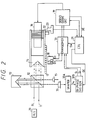
- Fig. 2 illustrates in block form an embodiment of the present invention, in which parts corresponding to those in Fig. 1 identified by the same reference numerals.
- single-wavelength reference light RL from a reference light source 29 as well as the light to be measured 11 are incident to the beam splitter 12, by which the reference light RL is split into two beams, one of which is reflected by the movable reflector 14 and the other of which is reflected by the fixed reflector 13.
- These two split light beams are combined by the beam splitter 12 into interference light, which is incident to a photodetector 31.
- the output level of the photodetector 31 varies one cycle each time the movable reflector 14 moves a distance corresponding to one-half of the wavelength ⁇ r of the reference light RL, that is, ⁇ r /2. Consequently, the number of cycles over which the level of the output signal from the photodetector 31 changes corresponds to the distance of travel of the movable reflector 14.
- the photodetector 31 yields a sinusoidal signal of a fixed period dependent on the wavelength of the reference light RL and the speed of travel of the reflector 14.
- the frequency of the output signal from the photodetector 31 provides a measurement standard to the signal frequency based on the interference light of the light to be measured 11 which is detected by the photodetector 15. It is preferable that the wavelength of the reference light RL be equal to or shorter than the wavelength of the light 11, because the shorter the wavelength, the higher the accuracy of the wavelength resolution.
- the reference light source 29 is, for example, a He-Ne gas laser of a 633 nm wavelength.
- the movable reflector 14 By the travel of the movable reflector 14 interference light, whose intensity varies repeatedly, is applied to the photodetector 31, by which it is converted into a sinusoidally-varying electric signal.
- the electric signal is applied to a waveform shaper 32A, by which it is shaped into a square wave signal Sq shown in Fig. 3.
- the square wave signal Sq is provided to a two-phase signal generator 32B, which serves as feedback signal generating means and derives therefrom two-phase signals S1 and S2 which are displaced 90° apart in phase from each other as depicted in Fig. 3.
- the square wave signal Sq in Fig. 3 When the movable reflector 14 is at a standstill, the square wave signal Sq in Fig. 3 is at either one of the levels "0" and "1".
- the control circuit 21 supplies the two-phase signal generator 32B with a direction control signal DC which specifies the direction in which the movable reflector 14 is to be moved, namely, designates in which direction the movable reflector 14 is to be moved.
- the control circuit 21 controls the two-phase signal generator 32B to generate the two-phase signals S1 and S2 so that the signal S1 leads the signal S2 by a phase angle of 90°.
- the signals S1 and S2 are produced so that the latter leads the former by a phase angle of 90°.
- the two-phase signals S1 and S2 are applied as feedback signals to the servo drive circuit 19.
- the two-phase signals S1 and S2 are obtained by frequency-dividing the square wave signal Sq down to 1/2 the frequency.
- the signals S1 and S2 are generated so that, for example, the former inverts its state upon each rise of the square wave signal Sq, whereas the latter inverts its state upon each fall of the signal Sq, as depicted in Fig. 3.
- the signal S1 thus obtained at the rise of the square wave signal Sq in the example of Fig. 3 leads the signal S2 obtained at the fall of the signal Sq, by a phase angle of 90°.
- the signal S2 is generated so that it inverts the state upon each rise of the square wave signal Sq, whereas the signal S1 is generated so that it inverts the state upon each fall of the signal Sq.
- Fig. 4 illustrates a specific example of the circuit construction of the two-phase signal generator 32B employed in the Fig. 2 embodiment.
- the direction control signal DC from the control circuit 21 is composed of two signals DC1 and DC2 representing a predetermined direction and a direction opposite thereto, respectively.
- the signals DC1 and DC2 are applied to the two-phase signal generator 32B via different wires.
- the signals DC1 and DC2 are always at the high level, and when the movable reflector 14 is to be moved in either one of the directions, the corresponding one of the signals DC1 and DC2 is made low-level for a fixed short period of time.
- the signals DC1 and DC2 refer to such low-level pulses.
- the two-phase signal generator 32B is made up of three D flip-flops 34, 35 and 36, an AND gate 37, an inverter 38 and a NOR gate 39.
- the D flip-flops 34 and 36 are cleared and the D flip-flop 35 is cleared or preset by the signal DC1 or DC2.
- the square wave signal Sq is applied to a clock terminal of the D flip-flop 34, which reads therein the high level provided at its data terminal to make its Q output high-level, and consequently the gate 37 is enabled, permitting the passage therethrough of the square wave signal Sq.
- the D flip-flop 36 is cleared, by which its inverted Q output goes to the high level. Accordingly, at the first fall of the square wave signal Sq from the gate 37, the high level of its inverted Q output is read into the D flip-flop 36 and its Q output goes low, after which the level of the Q output reverses upon each fall of the square wave signal Sq.
- the Q output of the D flip-flop 36 is output as the two-phase signal S2.
- the D flip-flop 35 has been cleared by the signal DC1 in advance, its inverted Q output is high, and at the first rise of the square wave signal Sq from the gate 37 the high level of the inverted Q output is read into the D flip-flop 35 to make its Q output high, after which the level of the Q output reverses upon each rise of the square wave signal Sq.
- the D flip-flop 35 has been preset by the signal DC2, its inverted Q output remain low; so that at the first rise of the square wave signal Sq from the gate 37 the D flip-flop 35 reads thereinto the low level of the inverted Q output to make its Q output low, after which the level of the Q output reverses upon each rise of the square wave signal Sq.
- the Q output of the D flip-flop 35 is output as the other two-phase signal S1. That is, the two-phase signal generator depicted in Fig. 4 is designed to generate the signal S2 which reverses its level upon each fall of the square wave signal Sq and the signal S1 which reverses its level upon each rise of the square wave signal Sq and which leads or lags the signal S2 by a phase angle of 90°, depending upon whether the applied direction signal is DC1 or DC2.
- the Fig. 2 embodiment also permits servo control of the linear motor 16 through utilization of feedback signal generating means including scale means related directly to the movement of the reflector 14, i.e. the linear scale 17 in this example, during standstill period of the movable reflector 14 and/or during movement of the movable reflector 14 except during measurement, and the linear scale 17 and the linear scale detector 18 are also provided as in the prior art.
- the two-phase signals D1, D2 output from the linear scale detector 18 and the two-phase signals S1, S2 output from the two-phase signal generator 32B are changed over by a changeover circuit 33 under control of the control circuit 21 and selected ones of the two-phase signals D1, D2 or S1, S2 are applied to the servo drive circuit 19.
- Control for shifting the movable reflector 14 to its reference position upon turning-ON of the power source switch is effected by applying the two-phase signal D1, D2 from the linear scale detector 18, and the movable reflector 14 is moved until the light blocking plate 22 enters into the photo interruptor 23.
- the movement of the movable reflector 14 during measurement is also carried out by applying the output of the linear scale detector 18 to the servo drive circuit 19.
- the two-phase signals S1, S2 of the phase corresponding to the direction of movement of the movable reflector 14 is output from the two-phase signal generator 32B as the movable reflector 14 moves, and the two-phase signals S1, S2 are applied to the servo drive circuit 19, by which the speed and distance of movement of the movable reflector 14 are controlled.
- the movement of the movable reflector 14 can be controlled with a high degree of accuracy.
- the linear motor 16 is driven in units of the half wavelength of the reference light RL and the wavelength of the reference light RL is 633 nm; hence, the movable reflector 14 can be moved smoothly with high resolution.
- the servo drive circuit 19 Upon completion of the driving of the linear motor 16 by the specified distance, the servo drive circuit 19 applies a movement end signal DE to the control circuit 21.
- the control circuit 21 When supplied with the movement end signal DE, the control circuit 21 applies a changeover control signal SW to the changeover circuit 33 to change its connection, providing the detected signals D1, D2 from the linear scale detector 18 to the servo drive circuit 19.
- the linear scale 17 may be a low-cost one whose resolution is low, for example, about 50 »m.
- the linear scale 17, the linear scale detector 18 and the changeover circuit 33 may be omitted and the outputs S1, S2 of the two-phase signal generator need to be applied directly to the servo drive circuit 19.
- the one two-phase pulse signal D1 from the linear scale detector 18 is applied, as a signal representing the amount of movement, to the changeover circuit 33 and a data terminal D of a D flip-flop 42, whereas the other two-phase pulse signal D2 is applied to a clock terminal CK of the D flip-flop 42.
- the Q output of the flip-flop 42 goes to a "1” or "0" depending upon which of the two-phase pulses D1 and D2 leads the other in phase, and the Q output is provided as the direction control signal to the changeover circuit 33.
- a magnetic single-phase signal generator, or a photo-mechanical single-phase signal generator by a combination of a photo interruptor and a slit, as a scaler, and a movement-direction sensor such as a velocity sensor may be used in place of the linear scale 17 and the linear scale detector 18.
- a sine-wave signal may be used as the signal indicating the amount of movement.
- the linear scale 17 may be replaced with a two-phase or single-phase rotating scaler which responds to the linear movement of the movable reflector 14 to rotate a roller to drive a rotary encoder and supplied its output to the changeover circuit 33.
- an absolute value type scale which has, as a whole, the functions of the linear scale 17, the detector 18, the light blocking plate 22 and the photo interruptor 23.
- the movement of the movable reflector 14 is normally placed under servo control through use of the output of the photodetector 31 as the feedback signal, and when the control system is out of order, the output of the linear scale 17 is used to effect the servo control to prevent runaway of the movable reflector 14.
- a feedback signal corresponding to the movement of the movable reflector is derived from an electric signal converted from interference light of reference light and the feedback signal is applied to the servo drive circuit; so that the movement of the movable reflector can be implemented with very short steps without essentially affecting the interference light of the light to be measured.
- the present invention does not call for adding any optical parts to the conventional interferometer and hence does not involve complex adjustment, and the feedback signal generating means, for example, the two-phase signal generator 32B can easily be formed by an electric circuit. Consequently, there is no need of using an expensive linear scale of high resolution.
Landscapes
- Physics & Mathematics (AREA)
- Spectroscopy & Molecular Physics (AREA)
- General Physics & Mathematics (AREA)
- Instruments For Measurement Of Length By Optical Means (AREA)
- Spectrometry And Color Measurement (AREA)
Claims (4)
- Michelson-Interferometer, umfassend
einen Strahlspalter (12) zum Aufspalten von einfallendem Licht in reflektiertes Licht und transmittiertes Licht,
einen feststehenden Reflektor (13), der relativ zu dem strahlspalter (12) fixiert ist, zum Reflektieren des reflektierten Lichts oder des transmittierten Lichts zurück zu dem Strahlspalter (12),
einen beweglichen Reflektor (14), der in einer Weise vorgesehen ist, daß er relativ zu dem Strahlspalter (12) vor und zurück bewegbar ist, zum Reflektieren des anderen Lichts, das heißt des transmittierten Lichts oder des reflektierten Lichts, zurück zu dem Strahlspalter,
eine Motoreinrichtung (16) zum linearen Bewegen des beweglichen Reflektors (14),
eine Servo-Treibereinrichtung (19) zum Antreiben der Motoreinrichtung (16) auf der Basis eines Rückkopplungssignals und eines Bewegungssteuersignals, welche die Bewegung des beweglichen Reflektors (14) steuert,
eine Referenzlichtquelleneinrichtung (29) zur Erzeugung von Referenzlicht (RL) einer festen Wellenlänge und zum Anlegen des Referenzlichts (RL) als das einfallende Licht an den Strahlspalter (12), und
einen Fotodetektor (31) zum Empfang von Interferenzlicht zwischen dem von dem feststehenden Reflektor (13) reflektierten Licht und dem von dem beweglichen Reflektor (14) reflektierten Licht von dem Strahlspalter (12) und zum Umsetzen des empfangenen Interferenzlichts in ein elektrisches Signal, wobei das Michelson-Interferometer gekennzeichnet ist durch:
eine Rückkopplungssignal-Generatoreinrichtung (32B) zur Erzeugung des Rückkopplungssignals auf der Basis des von dem Fotodetektor (31) ausgegebenen elektrischen Signals und eines Richtungssteuersignals (DC), das angibt, in welcher Richtung der bewegliche Reflektor (14) zu bewegen ist, und zur Lieferung des Rückkopplungssignals an die Servo-Treibereinrichtung (19), und
eine Steuereinrichtung (21) zur Erzeugung des Richtungssteuersignals, das der Rückkopplungssignal-Generatoreinrichtung (32B) geliefert wird, und des Bewegungssteuersignals, das der Servo-Steuereinrichtung (19) geliefert wird,
wobei die Rückkopplungssignal-Generatoreinrichtung (32B) eine Zwei-Phasen-Signalgeneratoreinrichtung ist, die als das der Servo-Treibereinrichtung (19) gelieferte Rückkopplungssignal von dem elektrischen Signal, das von dem Fotodetektor (31) geliefert wird, und von dem Richtungssteuersignal (DC), das von der Steuereinrichtung (21) geliefert wird, Zwei-Phasen-Signale (S₁, S₂) derselben Periode ableitet, von denen nach Maßgabe der Richtung, die das Richtungssteuersignal (DC) repräsentiert, eines dem anderen in der Phase voreilt. - Michelson-Interferometer, umfassend
einen Strahlspalter (12) zum Aufspalten von einfallendem Licht in reflektiertes Licht und transmittiertes Licht,
einen feststehenden Reflektor (13), der relativ zu dem Strahlspalter (12) fixiert ist, zum Reflektieren des reflektierten Lichts oder des transmittierten Lichts zurück zu dem Strahlspalter (12),
einen beweglichen Reflektor (14), der in einer Weise vorgesehen ist, daß er relativ zu dem Strahlspalter (12) vor und zurück bewegbar ist, zum Reflektieren des anderen Lichts, das heißt des transmittierten Lichts oder des reflektierten Lichts, zurück zu dem Strahlspalter,
eine Motoreinrichtung (16) zum linearen Bewegen des beweglichen Reflektors (14),
eine Servo-Treibereinrichtung (19) zum Antreiben der Motoreinrichtung (16) auf der Basis eines Rückkopplungssignals und eines Bewegungssteuersignals, welche die Bewegung des beweglichen Reflektors (14) steuert,
eine Referenzlichtquelleneinrichtung (29) zur Erzeugung von Referenzlicht (RL) einer festen Wellenlänge und zum Anlegen des Referenzlichts (RL) als das einfallende Licht an den Strahlspalter (12), und
einen Fotodetektor (31) zum Empfang von Interferenzlicht zwischen dem von dem feststehenden Reflektor (13) reflektierten Licht und dem von dem beweglichen Reflektor (14) reflektierten Licht von dem Strahlspalter (12) und zum Umsetzen des empfangenen Interferenzlichts in ein elektrisches Signal, wobei das Michelson-Interferometer gekennzeichnet ist durch:
eine erste Rückkopplungssignal-Generatoreinrichtung (32B) zur Erzeugung, auf der Basis des von dem Fotodetektor (31) ausgegebenen elektrischen Signals und eines Richtungssteuersignals (DC), das angibt, in welcher Richtung der bewegliche Reflektor (14) bewegt werden soll, eines ersten Rückkopplungssignals,
eine zweite Rückkopplungssignal-Generatoreinrichtung (18), enthaltend eine Skalenanordnung (17), die in direkter Verbindung mit der Bewegung des bewegliche Reflektors (14) steht, zur Erzeugung eines zweiten Rückkopplungssignals, das der Bewegung des beweglichen Reflektors (14) entspricht und von gleicher Art ist wie das erste Rückkopplungssignal,
eine Umschalteinrichtung (33) zum Schalten des ersten und des zweiten Rückkopplungssignals und zur Lieferung eines der beiden Rückkopplungssignale als das Rückkopplungssignal an die Servo-Treibereinrichtung (19), und
eine Steuereinrichtung (21) zur Erzeugung des Richtungssteuersignals (DC), das der Rückkopplungssignal-Generatoreinrichtung (32B) geliefert wird, und des Bewegungssteuersignals, das der Servo-Treibereinrichtung (19) geliefert wird, wobei die Steuereinrichtung (21) auch das Schalten der Umschalteinrichtung (33) steuert,
wobei die erste Rückkopplungssignal-Generatoreinrichtung (32B) eine Zwei-Phasen-Signalgeneratoreinrichtung ist, die als das der Servo-Treibereinrichtung (19) gelieferte Rückkopplungssignal von dem elektrischen Signal, das von dem Fotodetektor (31) geliefert wird, und von dem Richtungssteuersignal (DC), das von der Steuereinrichtung (21) geliefert wird, Zwei-Phasen-Signale (S₁, S₂) derselben Periode ableitet, von denen nach Maßgabe der Richtung, die das Richtungssteuersignal (DC) repräsentiert, eines dem anderen in der Phase voreilt. - Michelson-Interferometer nach Anspruch 2, bei dem die Steuereinrichtung (21) die Umschalteinrichtung (33) so steuert, daß, wenn der bewegliche Reflektor (14) in einem Bewegungszustand ist, das erste Rückkopplungssignal von der Umschalteinrichtung (33) an die Servo-Treibereinrichtung (19) geliefert wird, während, wenn sich der bewegliche Reflektor (14) im wesentlichen in einem stationären Zustand befindet, das zweite Rückkopplungssignal von der Umschalteinrichtung (13) an die Servo-Treibereinrichtung (19) geliefert wird.
- Michelson-Interferometer nach Anspruch 1 oder 2, bei dem die Zwei-Phasen-Signalgeneratoreinrichtung enthält: ein erstes Flipflop (35), das die Frequenz des ihm zugeführten elektrischen Signals durch 2 teilt und gelöscht oder voreingestellt wird, abhängig davon, ob das Richtungssteuersignal (DC) die eine oder die andere Richtung vorgibt, und ein zweites Flipflop (36), das die invertierte Version des elektrischen Signals erhält, dessen Frequenz durch 2 teilt und von dem Richtungssteuersignal (DC) gelöscht wird, wobei die Ausgangssignale des ersten und des zweiten Flipflops (35, 36) als die Zwei-Phasen-Signale (S₁, S₂) ausgegeben werden.
Applications Claiming Priority (3)
| Application Number | Priority Date | Filing Date | Title |
|---|---|---|---|
| JP102336/90 | 1990-04-18 | ||
| JP10233690 | 1990-04-18 | ||
| PCT/JP1991/000506 WO1991016606A1 (fr) | 1990-04-18 | 1991-04-17 | Interferometre michelson |
Publications (3)
| Publication Number | Publication Date |
|---|---|
| EP0478801A1 EP0478801A1 (de) | 1992-04-08 |
| EP0478801A4 EP0478801A4 (en) | 1992-08-19 |
| EP0478801B1 true EP0478801B1 (de) | 1995-02-08 |
Family
ID=14324670
Family Applications (1)
| Application Number | Title | Priority Date | Filing Date |
|---|---|---|---|
| EP91908474A Expired - Lifetime EP0478801B1 (de) | 1990-04-18 | 1991-04-17 | Michelson interferometer |
Country Status (5)
| Country | Link |
|---|---|
| US (1) | US5270790A (de) |
| EP (1) | EP0478801B1 (de) |
| KR (2) | KR910018773A (de) |
| DE (1) | DE69107269T2 (de) |
| WO (1) | WO1991016606A1 (de) |
Families Citing this family (15)
| Publication number | Priority date | Publication date | Assignee | Title |
|---|---|---|---|---|
| JPH0719965A (ja) * | 1993-06-30 | 1995-01-20 | Ando Electric Co Ltd | 光波長計 |
| JPH07209085A (ja) * | 1994-01-19 | 1995-08-11 | Yokogawa Electric Corp | フーリエ分光器 |
| FR2716722B1 (fr) * | 1994-02-25 | 1996-04-05 | France Telecom | Système interférométrique de détection et de localisation de défauts réflecteurs de structures guidant la lumière. |
| JPH07239272A (ja) * | 1994-02-28 | 1995-09-12 | Ando Electric Co Ltd | 光波長計 |
| JPH07270245A (ja) * | 1994-03-31 | 1995-10-20 | Ando Electric Co Ltd | 測長器を用いた光波長計 |
| FR2718230B1 (fr) * | 1994-04-05 | 1996-06-21 | Aerospatiale | Ligne à retard pour interféromètre. |
| US5495767A (en) * | 1994-07-26 | 1996-03-05 | Alfred University | Laser vibrometer |
| DE19504444B4 (de) * | 1995-02-10 | 2004-05-13 | Carl Zeiss Jena Gmbh | Interferometeranordnung mit verstellbarer optischer Weglängendifferenz |
| US5647032A (en) * | 1995-08-24 | 1997-07-08 | Kowa Company, Ltd. | Interferometers for measuring coherence length and high-speed switching of laser light |
| DE19714202A1 (de) * | 1997-04-07 | 1998-10-15 | Bosch Gmbh Robert | Vorrichtung zum optischen Prüfen von Oberflächen |
| US6186636B1 (en) | 1999-06-11 | 2001-02-13 | Design Rite, Llc. | Apparatus for illuminating a portable electronic or computing device |
| US8159737B2 (en) * | 2009-04-27 | 2012-04-17 | Phase Sensitive Innovations, Inc. | Controlling the phase of optical carriers |
| WO2010148282A2 (en) * | 2009-06-18 | 2010-12-23 | Paul Prucnal | An optical switch using a michelson interferometer |
| FR2972797B1 (fr) * | 2011-03-17 | 2019-12-13 | Thales | Systeme et procede de metrologie applique a un interferometre d'analyse a distance d'un compose |
| KR102387652B1 (ko) | 2020-10-23 | 2022-04-15 | 김재욱 | 투표용지 자동감지장치 |
Family Cites Families (16)
| Publication number | Priority date | Publication date | Assignee | Title |
|---|---|---|---|---|
| GB1185037A (en) * | 1966-03-23 | 1970-03-18 | Rank Organisation Ltd | Improvements in or relating to Measurements Devices |
| JPS5324594B2 (de) * | 1974-03-01 | 1978-07-21 | ||
| US4132940A (en) * | 1975-04-04 | 1979-01-02 | Nasa | Apparatus for providing a servo drive signal in a high-speed stepping interferometer |
| JPS5324594A (en) * | 1976-08-18 | 1978-03-07 | Fujikura Ltd | Connecting plastic sheathed cable |
| JPS53124456A (en) * | 1977-04-06 | 1978-10-30 | Jeol Ltd | Reference signal generator |
| US4413908A (en) * | 1982-03-05 | 1983-11-08 | Bio-Rad Laboratories, Inc. | Scanning interferometer control systems |
| JPS59163525A (ja) * | 1983-03-08 | 1984-09-14 | Japan Spectroscopic Co | 連続駆動型マイケルソン干渉計の可動鏡駆動装置 |
| JPS61501340A (ja) * | 1984-03-05 | 1986-07-03 | ベツクマン インスツルメンツ インコ−ポレ−テツド | ミラ−スキャン速度制御装置 |
| US4575246A (en) * | 1984-03-05 | 1986-03-11 | Japan Spectroscopic Co., Ltd. | Michelson interferometer |
| US4660979A (en) * | 1984-08-17 | 1987-04-28 | At&T Technologies, Inc. | Method and apparatus for automatically measuring semiconductor etching process parameters |
| JPS61234318A (ja) * | 1985-04-09 | 1986-10-18 | Shimadzu Corp | 干渉計の可動鏡の速度制御装置 |
| JPS62103531A (ja) * | 1985-10-30 | 1987-05-14 | Jeol Ltd | マイケルソン干渉計における移動鏡移動方向判定方法 |
| US4799001A (en) * | 1987-07-23 | 1989-01-17 | Nicolet Corporation | Start of scan circuit for FTIR spectrometer |
| US4847878A (en) * | 1988-03-31 | 1989-07-11 | Nicolet Instrument Corporation | Method and apparatus for determining mirror position in a fourier-transform infrared spectrometer |
| JPH07104206B2 (ja) * | 1988-03-31 | 1995-11-13 | 株式会社島津製作所 | 二光束干渉計 |
| US5180057A (en) * | 1991-03-15 | 1993-01-19 | Samsonite Corporation | Expandable garment bag and hanger bar therefor |
-
1991
- 1991-04-07 US US07/778,947 patent/US5270790A/en not_active Expired - Lifetime
- 1991-04-09 KR KR1019910005651A patent/KR910018773A/ko not_active Withdrawn
- 1991-04-17 WO PCT/JP1991/000506 patent/WO1991016606A1/ja not_active Ceased
- 1991-04-17 EP EP91908474A patent/EP0478801B1/de not_active Expired - Lifetime
- 1991-04-17 KR KR1019910701768A patent/KR920701800A/ko not_active Ceased
- 1991-04-17 DE DE69107269T patent/DE69107269T2/de not_active Expired - Fee Related
Also Published As
| Publication number | Publication date |
|---|---|
| KR920701800A (ko) | 1992-08-12 |
| EP0478801A1 (de) | 1992-04-08 |
| DE69107269D1 (en) | 1995-03-23 |
| KR910018773A (ko) | 1991-11-30 |
| US5270790A (en) | 1993-12-14 |
| EP0478801A4 (en) | 1992-08-19 |
| DE69107269T2 (de) | 1995-07-27 |
| WO1991016606A1 (fr) | 1991-10-31 |
Similar Documents
| Publication | Publication Date | Title |
|---|---|---|
| EP0478801B1 (de) | Michelson interferometer | |
| US5359409A (en) | Diffraction grating position sensing and control for a scanning monochromator | |
| EP0401799B1 (de) | Längenmessgerät | |
| US4285012A (en) | Light beam scanner | |
| US4800270A (en) | Galvanometric optical scanning system having a pair of closely located synchronization | |
| JPH0212025A (ja) | フーリエ変換赤外線分光計においてミラー位置を判定する方法及び装置 | |
| JP2731565B2 (ja) | 測距センサー | |
| WO1988002846A1 (en) | Optical measuring probe | |
| EP0364984B1 (de) | Multimoden-Halbleiterlaser-Interferometer | |
| US5198873A (en) | Encoder utilizing interference using multi-mode semiconductor laser | |
| US5182613A (en) | Position detecting apparatus generating periodic detection signals having equal third and fifth harmonic components | |
| JP3216146B2 (ja) | マイケルソン干渉計 | |
| US4912320A (en) | Optical type encoder including diffraction grating for producing interference fringes that are processed to measure displacement | |
| JP3795257B2 (ja) | 測長装置および測長補正装置 | |
| SU794644A1 (ru) | Устройство дл управлени сканиро-ВАНиЕМ пРи ВыВОдЕ гРАфичЕСКОйиНфОРМАции из эВМ | |
| JPH0244173Y2 (de) | ||
| SU1441189A1 (ru) | Измеритель длин волн | |
| JPH0476049B2 (de) | ||
| SU1509625A1 (ru) | Устройство дл измерени интенсивности линии в оптическом спектре | |
| JP2838171B2 (ja) | 位相シフトマイクロフィゾー干渉計 | |
| SU1337656A2 (ru) | Устройство дл измерени линейных перемещений сканирующего зеркала Фурье-спектрометра | |
| Lo et al. | Microstep of digital control for step motor and its test using a laser interferometer measurement system | |
| SU1439398A1 (ru) | Фотоэлектрический способ измерени перемещений излучател и устройство дл его осуществлени | |
| JP2585857B2 (ja) | 位置検出装置 | |
| SU1114881A1 (ru) | Устройство дл измерени линейных перемещений объекта |
Legal Events
| Date | Code | Title | Description |
|---|---|---|---|
| PUAI | Public reference made under article 153(3) epc to a published international application that has entered the european phase |
Free format text: ORIGINAL CODE: 0009012 |
|
| 17P | Request for examination filed |
Effective date: 19911205 |
|
| AK | Designated contracting states |
Kind code of ref document: A1 Designated state(s): DE GB |
|
| A4 | Supplementary search report drawn up and despatched |
Effective date: 19920702 |
|
| AK | Designated contracting states |
Kind code of ref document: A4 Designated state(s): DE GB |
|
| 17Q | First examination report despatched |
Effective date: 19931019 |
|
| GRAA | (expected) grant |
Free format text: ORIGINAL CODE: 0009210 |
|
| AK | Designated contracting states |
Kind code of ref document: B1 Designated state(s): DE |
|
| REF | Corresponds to: |
Ref document number: 69107269 Country of ref document: DE Date of ref document: 19950323 |
|
| PLBE | No opposition filed within time limit |
Free format text: ORIGINAL CODE: 0009261 |
|
| STAA | Information on the status of an ep patent application or granted ep patent |
Free format text: STATUS: NO OPPOSITION FILED WITHIN TIME LIMIT |
|
| 26N | No opposition filed | ||
| PGFP | Annual fee paid to national office [announced via postgrant information from national office to epo] |
Ref country code: DE Payment date: 20020430 Year of fee payment: 12 |
|
| PG25 | Lapsed in a contracting state [announced via postgrant information from national office to epo] |
Ref country code: DE Free format text: LAPSE BECAUSE OF NON-PAYMENT OF DUE FEES Effective date: 20031101 |