EP0478360B1 - Technique d'assemblage de circuits imprimés de grande diversité - Google Patents
Technique d'assemblage de circuits imprimés de grande diversité Download PDFInfo
- Publication number
- EP0478360B1 EP0478360B1 EP91308847A EP91308847A EP0478360B1 EP 0478360 B1 EP0478360 B1 EP 0478360B1 EP 91308847 A EP91308847 A EP 91308847A EP 91308847 A EP91308847 A EP 91308847A EP 0478360 B1 EP0478360 B1 EP 0478360B1
- Authority
- EP
- European Patent Office
- Prior art keywords
- circuit board
- cell
- boards
- parts
- family
- Prior art date
- Legal status (The legal status is an assumption and is not a legal conclusion. Google has not performed a legal analysis and makes no representation as to the accuracy of the status listed.)
- Expired - Lifetime
Links
Images


Classifications
-
- H—ELECTRICITY
- H05—ELECTRIC TECHNIQUES NOT OTHERWISE PROVIDED FOR
- H05K—PRINTED CIRCUITS; CASINGS OR CONSTRUCTIONAL DETAILS OF ELECTRIC APPARATUS; MANUFACTURE OF ASSEMBLAGES OF ELECTRICAL COMPONENTS
- H05K13/00—Apparatus or processes specially adapted for manufacturing or adjusting assemblages of electric components
- H05K13/08—Monitoring manufacture of assemblages
- H05K13/085—Production planning, e.g. of allocation of products to machines, of mounting sequences at machine or facility level
-
- H—ELECTRICITY
- H05—ELECTRIC TECHNIQUES NOT OTHERWISE PROVIDED FOR
- H05K—PRINTED CIRCUITS; CASINGS OR CONSTRUCTIONAL DETAILS OF ELECTRIC APPARATUS; MANUFACTURE OF ASSEMBLAGES OF ELECTRICAL COMPONENTS
- H05K13/00—Apparatus or processes specially adapted for manufacturing or adjusting assemblages of electric components
- H05K13/08—Monitoring manufacture of assemblages
- H05K13/087—Equipment tracking or labelling, e.g. tracking of nozzles, feeders or mounting heads
-
- Y—GENERAL TAGGING OF NEW TECHNOLOGICAL DEVELOPMENTS; GENERAL TAGGING OF CROSS-SECTIONAL TECHNOLOGIES SPANNING OVER SEVERAL SECTIONS OF THE IPC; TECHNICAL SUBJECTS COVERED BY FORMER USPC CROSS-REFERENCE ART COLLECTIONS [XRACs] AND DIGESTS
- Y10—TECHNICAL SUBJECTS COVERED BY FORMER USPC
- Y10T—TECHNICAL SUBJECTS COVERED BY FORMER US CLASSIFICATION
- Y10T29/00—Metal working
- Y10T29/49—Method of mechanical manufacture
- Y10T29/49002—Electrical device making
- Y10T29/49117—Conductor or circuit manufacturing
- Y10T29/49124—On flat or curved insulated base, e.g., printed circuit, etc.
- Y10T29/4913—Assembling to base an electrical component, e.g., capacitor, etc.
Definitions
- the present invention relates generally to work allocation in an assembly line, and more specifically to operation assignment problems in a printed circuit (PC) board assembly process.
- PC printed circuit
- SMT surface mount technology
- the "greedy board” approach proved especially useful for the problem at hand because it weighs volume against part commonality when assigning boards to cells. Other group technology techniques typically ignore the impact of volume.
- the algorithm requires a list of boards, board volumes. and a bill of materials for each board.
- the proposed SMT line needs to meet a number of stringent criteria in order to be considered successful. First and foremost, it has to deliver high-quality, lowmost products. It also has to operate consistent with just-in-time philosophy, which means little work-in-progress inventory (WIP) and short cycle times. Underlying these constraints is the expectation of rapid growth of SMT volumes and types of products, so the new line's design also has to support a sound growth strategy with little change in layout or operating policy.
- WIP work-in-progress inventory
- temporal cells may be designed to run at different times on the same set of equipment (two series Fuji CP-IIIs).
- the components in the first cell, comprising the highest volume boards, may be fixed on the entire first machine and half of the second.
- the remaining bank of the second machine may be used to set up additional cells to run all remaining boards.
- high-volume boards could run at any time, while operators set up cells for low-volume work during high-volume board production. This approach improves machine utilization, accommodates changing mix, and permits simple operational alternatives.
- colour coding may be used to identify all component parts included in a cell, and number identifications may be used to facilitate proper sequential placement of the component parts in the feeder slots of the machines.
- the equipment set for the line included one Fuji GSP-II stencil machine, two Fuji CP-III high-speed pick-and-place machines (to be arranged either in series with the other machines or in parallel), a Fuji IP-II general-purpose pick-and-place machine, and a Vitronics infrared solder reflow oven.
- a preliminary analysis of demand on each of these machines and their respective capacities revealed that the bottleneck process would be the two CP-IIIs, regardless of the arrangement of the two machines, and subsequent efforts focused on developing a plan for the use of those machines.
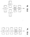
- Figure 1 a and 1 b show the two material flows considered.
- CP-IIIs make them the bottleneck is that it takes a long time to set up new parts on the machine when changing from batch to batch.
- Each machine holds about 100 parts (part capacity is a function of individual part sizes, which are variable).
- the site supports hundreds of parts more than the capacity of the machines, making it impossible to put all parts on line, even with the machines in series. Between any two batches, there would be dozens of CP-III parts to set up.
- the expected average parts setup time from one run to the next would be about 60 minutes.
- actual run times for average boards at the site are about four minutes.
- the run would consist of 60% setup and 40% running time on a CP-III. With equipment costs as high as they are, this sort of machine utilization was unacceptable.
- Group technology traditionally refers to the manufacture of parts or products grouped together into "families", or “cells”, on the basis of similarities between key attributes.
- the similarities night be a function of the design, the necessary manufacturing processes, or both.
- the grouping of similar products permits the same tools and fixtures to be used, vastly reducing the time spent setting up each batch. products that have distinctly different characteristics run in another cell on a different machine, or at a different time on the same machines, following a single major setup.
- New products resembling existing products can be introduced with little trouble or expense, but completely new designs that do not fit in an established group might cost more due to increased setups. Thus, the use of clever grouping in manufacturing can reduce costs. Designers can consider the cost of deviating from current designs as they create new products.
- the details of the greedy board heuristic are straightforward. Again, the only data required is the list of part numbers on each board and the expected demand for each board. Specifically, cells are added one at a time by selecting the remaining unassigned boards with the lowest ratio of new parts added to the cell to board volume.
- Jaguar is lowest, so it is the first board added to the cell. It has the highest product volume added per part slot consumed. Jaguar adds five components (B,D,F,H and N); assume that there is a limit of eight parts for the cell for this example.
- puma has the lowered ratio, since its part set is a complete subset of the parts already in the cell. Since adding puma to the cell does not require the addition of any parts, the parts-to-volume ratios above still apply. The next lowest is appaloosa, which adds two new parts to the cell (E and P). That brings the total number of parts for the cell to seven, still within the physical constraint.
- the second cell is defined by following the same procedure for the remaining boards: current parts in Cell 2: none Board New Parts Volume Ratio morgan 4 1100 0.0036* ocelot 4 668 0.0060 tarzan 4 900 0.0044
- Tarzan is added, bringing the total part count to six in the cell (A,F,J,K,M,N). Ocelot still has four parts not in the cell, so it will not fit in Cell 2 without violating the total part ceiling. It must go in Cell 3. Note that Cell 2 is left with two unused part slots, and Cell 3 has four unused slots that can be used to accommodate new boards.
- the final cell definitions are: Cell Board Volume Parts 1 5532 B,C,D,E,F,H,N,P 2 2000 A,F,J,K,M,N 3 668 G,H,Q,L
- Cell 1 contains 67% of the total board volume; the volume falls off precipitously with the succeeding cells. Some parts appear in more than one cell.
- the greedy board heuristic performs well when high setup costs dominate placement costs.
- the goal is a list of component part numbers to dedicate on the machines.
- a cell is defined by adding boards one at a time until the physical machine constraint is reached.
- the heuristic greedily adds boards to the cell until no more fit. Component part volume is of no consequence. Rather, the volume of boards produced by the cell drives the solution.
- the SMT PCA situation called for the use of the greedy board heuristic because of the time required for setups on the CP-IIIs.
- the heuristic was used to define one cell at a time, ultimately producing a complete list of cells to run at different times on the same machines.
- the first pass of the heuristic defined the first cell, filled primarily with the highest volume boards (and other boards with high part overlap).
- the second and subsequent passes were made after removing the first cell's boards, essentially starting fresh each time but pulling from an increasingly smaller set of boards.
- a feature of the Fuji CP-IIIs is that each machine is actually split into two banks, each holding 50 parts. It is possible with this split-bank feature to run the machine with only one of the banks on line; the other bank can be off line. This permits an operator to work on setting up half the machine while the other bank is busy placing parts on boards.
- the feature allowed a more refined solution to the problem.
- the first cell, Cell 1 was defined so that it would use three of the four available part banks, and it would hold about 150 different parts. Since the first cell defined using the greedy board heuristic contains the highest volume boards, it would be used frequently in the course of a normal production day. To make quick response to demand for one of the high volume boards possible, this cell was kept on line at all tines. That is, the parts in Cell 1 were dedicated.
- Figure 2 shows how a day's work might flow through the line.
- Cell 1 boards will be built while Cell 2 is being set up. Then, once the setup for Cell 2 is complete, current demand for boards in that cell will be produced. Once that demand is satisfied, more Cell 1 boards will run and the next cell will be set up, as demand warrants.
- a board in any cell can be started through the line with a maximum delay of only about an hour. That is the time required to completely tear down one setup on the fourth bank and install another. Cell 1 boards could be built during the setup time, too. If the change requires building a board in Cell 1, which would be the most likely event, then the board could be run immediately, since that cell is always set up.
- the Ip-II general purpose pick-and-place machine
- the Ip-II had unused capacity
- parts unique to a single board were moved to the Ip-II. Those parts would have a limited contribution to any production cell, since they would only be used for one board.
- Parts originally classified as Cp-III parts were reassigned to the IP-II on a board-to-board basis, and the material list used to define the CP-III cells was modified accordingly. Calculations showed that the additional time required to set up the IP-II would not jeopardize the flow, the Cp-IIIs would still be the bottleneck and the IP-II would still have some idle time.
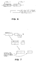
- Figure 3 shows how the different component parts constituting each cell are coded for easy identification by the operators.
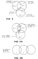
- Figs 5A and 5B show alternative situations in which a plurality of parts can be included in more than one cell. In Fig.5A there is a high overlap (corresponding to many parts) between cells 2 and 3 and not much overlap (corresponding to very few parts) between all three cells.
- the group technology solution also has a positive effect on quality. Since the parts for 75% of the board volume (Cell 1) are dedicated to machine slots, those boards do not suffer defects due to errors in part set up. For the remaining 25% of the board volume falling into other cells, the part set up is so simplified due to colored tape labelling that set up errors are virtually eliminated. Since many small SMT parts are unmarked by the vendor, defects due to part set up errors cannot be detected visually and are not found until the test step at the end of the process. By the time an error is discovered, a number of boards may have been produced, generating a great deal of repair work. Thus, eliminating or reducing set up errors has a significant impact on both quality and the anticipated cost of repair.
- Another advantage of this approach is a reduction in the number of production personnel required to run the line. Since part setups occur on only one CP-III, a single operator can run both CP-III's.
- this solution allows for growth as volumes and numbers of board types increase.
- a second line with the same configuration will be installed. This second line will be given a different set of cells, with many boards fitting cells on both lines to allow for load balancing.
- the group technology approach incorporating the use of the split bank feature to take cell set ups off-line met all of the goals for a process design.
- the goal of flexibility to build any board in any quantity as requested by the demand-pull system was net by the virtual elimination of batch setup tine.
- Overall system cost was reduced by increasing line efficiency (run time approaching 100%). Savings are also attributed to reduced finished goods inventories, reduced defects, and reduced production personnel.
- the series configuration provides a smooth, linear flow, minimizing queuing on the line. This flow keeps levels of WIP and cycle time as low as possible.
Claims (6)
- Procédé d'assemblage de composants sur une pluralité d'ensembles de panneaux de circuits, les ensembles nécessitant collectivement un nombre de composants différents supérieur à ce que peut fabriquer simultanément un dispositif de production, ledit dispositif comprenant des groupes de composants multiples, le procédé comprenant les étapes consistant à :a) choisir une première famille d'ensembles de panneaux de circuits en :i) en choisissant un premier ensemble de panneaux de circuits parmi la pluralité d'ensembles de panneaux de circuits pour lequel on a le plus faible rapport du nombre de composants différents devant être disposés sur un panneau de circuits de cet ensemble au volume de panneaux de circuits dans cet ensemble;ii) en choisissant ultérieurement un autre ensemble de panneaux de circuits parmi les ensembles restants de panneaux de circuits, qui présente le rapport le plus faible du nombre de composants différents devant être disposés sur un panneau de circuits de cet ensemble, diminué du nombre de composants différents déjà requis pour un ensemble de panneaux de circuits choisi précédemment, au volume des panneaux de circuits dans cet ensemble; etiii) en répétant l'étape (ii) en choisissant d'autres ensembles de panneaux de circuits tant que le nombre total de composants différents requis ne dépasse pas la capacité d'un nombre prédéterminé de groupes de composants du dispositif de production;b) préparer le dispositif de production en insérant les composants pour la première famille d'ensembles de panneaux de circuits, dans le nombre prédéterminé de groupes de composants;c) faire fonctionner le dispositif de production pour disposer les composants pour la première famille d'ensembles de panneaux de circuits dans leur position d'installation sur les panneaux de circuits;d) sélectionner une seconde famille d'ensembles de panneaux de circuits en mettant en oeuvre l'étape (a) en rapport à des ensembles de panneaux de circuits non contenus dans la première famille et en rapport avec les groupes restants de composants du dispositif de production;e) préparer le dispositif de production en insérant les composants pour la seconde famille d'ensembles de panneaux de circuits dans les groupes restants de composants du dispositif de production; etf) faire fonctionner le dispositif de production, après avoir exécuté la dernière étape de préparation (e), pour placer les composants pour la seconde famille d'ensembles de panneaux de circuits dans leur position d'installation sur les panneaux de circuits.
- Dispositif selon la revendication 1, dans lequel le dispositif de production comprend deux machines de production séparées (CP-III 1,CP-III 2) en série, ce qui conduit au fait que ledit nombre prédéterminé de groupes de composants disponible pour la première famille est plus élevé.
- Procédé selon la revendication 2, selon lequel les deux machines de production séparées utilisées dans lesdites étapes de fonctionnement comprennent certains composants communs.
- Procédé selon l'une quelconque des revendications précédentes, incluant un codage visuel des composants requis lors de l'étape a) de la revendication 1.
- Procédé selon l'une quelconque des revendications précédentes, incluant un codage visuel des composants requis lors de l'étape d) de la revendication 1.
- Procédé selon l'une quelconque des revendications précédentes, dans lequel les étapes d) et e) de la revendication 1 sont exécutées pendant l'étape c) de la revendication 1.
Applications Claiming Priority (2)
| Application Number | Priority Date | Filing Date | Title |
|---|---|---|---|
| US589748 | 1990-09-28 | ||
| US07/589,748 US5170554A (en) | 1990-09-28 | 1990-09-28 | High mix printed circuit assembly technique |
Publications (2)
| Publication Number | Publication Date |
|---|---|
| EP0478360A1 EP0478360A1 (fr) | 1992-04-01 |
| EP0478360B1 true EP0478360B1 (fr) | 1996-07-17 |
Family
ID=24359351
Family Applications (1)
| Application Number | Title | Priority Date | Filing Date |
|---|---|---|---|
| EP91308847A Expired - Lifetime EP0478360B1 (fr) | 1990-09-28 | 1991-09-27 | Technique d'assemblage de circuits imprimés de grande diversité |
Country Status (6)
| Country | Link |
|---|---|
| US (1) | US5170554A (fr) |
| EP (1) | EP0478360B1 (fr) |
| JP (1) | JPH04246897A (fr) |
| KR (1) | KR930007321A (fr) |
| DE (1) | DE69120887T2 (fr) |
| HK (1) | HK33297A (fr) |
Families Citing this family (32)
| Publication number | Priority date | Publication date | Assignee | Title |
|---|---|---|---|---|
| US5258915A (en) * | 1990-09-28 | 1993-11-02 | Hewlett-Packard Company | System and method for optimum operation assignments in printed circuit board manufacturing |
| US5325305A (en) * | 1992-07-24 | 1994-06-28 | The Boeing Company | Automated setup verification system |
| DE19502434A1 (de) * | 1994-04-29 | 1995-11-02 | Hewlett Packard Co | System und Verfahren zur inkrementalen Herstellung von Schaltungsplatinen |
| JP3552806B2 (ja) * | 1995-09-13 | 2004-08-11 | 松下電器産業株式会社 | 部品実装方法 |
| MX9709038A (es) * | 1996-11-25 | 1998-08-30 | Samsung Electronics Co Ltd | Sistema y metodo de produccion de montajes de tableros de circuitos impresos. |
| AU7273198A (en) * | 1997-05-01 | 1998-11-24 | Motorola, Inc. | Dynamically reconfigurable assembly line for electronic products |
| KR100369401B1 (ko) * | 2000-04-03 | 2003-01-29 | (주) 이우티이씨 | 자기장을 이용한 매설 배관 위치 측정 시스템 |
| DE10023358A1 (de) * | 2000-05-12 | 2001-11-29 | Siemens Ag | Fertigungslinie für die einseitige und doppelseitige Bestückung von Leiterplatten |
| JP2003030250A (ja) * | 2001-07-12 | 2003-01-31 | Oki Electric Ind Co Ltd | プリント基板設計工数見積りシステムと見積りプログラム |
| US6829514B2 (en) * | 2003-01-17 | 2004-12-07 | Motorola, Inc. | Balancing workloads in an electronics assembly factory |
| US7457128B2 (en) * | 2005-07-22 | 2008-11-25 | Hewlett-Packard Development Company, L.P. | Flexible cell configuration for multi-processor systems |
| DE102009013353B3 (de) * | 2009-03-16 | 2010-10-07 | Siemens Aktiengesellschaft | Verfahren zur Bestimmung von Rüstungen für konstante Tische von Bestückautomaten |
| DE102012211810A1 (de) * | 2012-07-06 | 2014-02-20 | Siemens Aktiengesellschaft | Bildung von Rüstfamilien auf Bestückungslinien |
| JP5959738B2 (ja) * | 2012-07-06 | 2016-08-02 | シーメンス アクチエンゲゼルシヤフトSiemens Aktiengesellschaft | 複数のプリント基板を各実装ラインへと割り当てるための方法 |
| JP2015531159A (ja) * | 2012-07-06 | 2015-10-29 | シーメンス アクチエンゲゼルシヤフトSiemens Aktiengesellschaft | 複数のプリント基板を各実装ラインへと割り当てるための方法 |
| EP2842402B1 (fr) * | 2012-07-06 | 2018-09-05 | Siemens Aktiengesellschaft | Affectation de cartes de circuits imprimés sur des lignes de montage |
| DE102012221258A1 (de) * | 2012-11-21 | 2014-05-22 | Siemens Aktiengesellschaft | Optimieren von Rüstfamilien |
| JP6475245B2 (ja) * | 2014-08-08 | 2019-02-27 | 株式会社Fuji | 基板生産方法及び基板生産の条件決定方法 |
| DE102014222940A1 (de) * | 2014-11-11 | 2016-05-12 | Siemens Aktiengesellschaft | Bestücken von Leiterplatten |
| DE102014222936A1 (de) * | 2014-11-11 | 2016-05-12 | Siemens Aktiengesellschaft | Bestücken von Leiterplatten |
| DE102014225713A1 (de) * | 2014-12-12 | 2016-06-16 | Siemens Aktiengesellschaft | Verfahren und System zur Bestückung von Leiterplatten sowie Computerprogrammprodukt zur Durchführung des Verfahrens |
| DE102015200420A1 (de) | 2015-01-14 | 2016-07-14 | Siemens Aktiengesellschaft | Verfahren und System zur Bestückung von Leiterplatten |
| DE102015200414A1 (de) * | 2015-01-14 | 2016-07-14 | Siemens Aktiengesellschaft | Verfahren und System zur Bestückung von Leiterplatten |
| CN107409491B (zh) * | 2015-03-05 | 2020-04-24 | 株式会社富士 | 安装管理装置 |
| DE102015206741A1 (de) * | 2015-04-15 | 2016-10-20 | Siemens Aktiengesellschaft | Bildung von Rüstfamilien für ein Bearbeitungssystem mit einer Werkzeugmaschine |
| CN105072813A (zh) * | 2015-08-13 | 2015-11-18 | 广州杰赛科技股份有限公司 | 一种印制板组合生产方法 |
| WO2018008157A1 (fr) * | 2016-07-08 | 2018-01-11 | 富士機械製造株式会社 | Système de création de plan de production et procédé de création de plan de production |
| EP3474650B1 (fr) * | 2017-10-19 | 2020-12-09 | Sick Ag | Procédé d'élaboration d'un ensemble d'adaptation pour une machine de montage de composants |
| KR102155013B1 (ko) * | 2018-02-27 | 2020-09-14 | 한화정밀기계 주식회사 | 다중 pcb를 제작하는 복수 피더 베이스로 구성된 단일 마운터에 대한 피더 배치 방법 |
| US10657297B2 (en) * | 2018-06-01 | 2020-05-19 | Mentor Graphics Corporation | Part number consolidation in printed circuit board assembly design |
| WO2020121402A1 (fr) * | 2018-12-11 | 2020-06-18 | 株式会社Fuji | Système de montage et procédé d'agencement d'unités d'alimentation de composants |
| EP4231800A1 (fr) * | 2022-02-22 | 2023-08-23 | Siemens Aktiengesellschaft | Procédé mis en uvre par ordinateur destiné à la détermination d'une quantité partielle de types de module d'une quantité déterminée de types de module et d'une armure fixe modifiée associée |
Family Cites Families (4)
| Publication number | Priority date | Publication date | Assignee | Title |
|---|---|---|---|---|
| US4651863A (en) * | 1983-08-31 | 1987-03-24 | Westinghouse Electric Corp. | System for assembling electronic component kits |
| JPH0668696B2 (ja) * | 1985-02-22 | 1994-08-31 | 株式会社日立製作所 | 挿入機用ncデータ作成方法 |
| US4694570A (en) * | 1985-11-21 | 1987-09-22 | Amistar Corporation | Surface mounted component transport mechanism |
| NL8900027A (nl) * | 1989-01-06 | 1990-08-01 | Philips Nv | Werkwijze en inrichting voor het plaatsen van onderdelen op een drager. |
-
1990
- 1990-09-28 US US07/589,748 patent/US5170554A/en not_active Expired - Lifetime
-
1991
- 1991-09-27 KR KR1019910016916A patent/KR930007321A/ko not_active Application Discontinuation
- 1991-09-27 DE DE69120887T patent/DE69120887T2/de not_active Expired - Fee Related
- 1991-09-27 EP EP91308847A patent/EP0478360B1/fr not_active Expired - Lifetime
- 1991-09-30 JP JP3251647A patent/JPH04246897A/ja active Pending
-
1997
- 1997-03-20 HK HK33297A patent/HK33297A/xx not_active IP Right Cessation
Also Published As
| Publication number | Publication date |
|---|---|
| DE69120887T2 (de) | 1996-11-28 |
| HK33297A (en) | 1997-03-27 |
| US5170554A (en) | 1992-12-15 |
| DE69120887D1 (de) | 1996-08-22 |
| KR930007321A (ko) | 1993-04-22 |
| EP0478360A1 (fr) | 1992-04-01 |
| JPH04246897A (ja) | 1992-09-02 |
Similar Documents
| Publication | Publication Date | Title |
|---|---|---|
| EP0478360B1 (fr) | Technique d'assemblage de circuits imprimés de grande diversité | |
| CA2038939C (fr) | Dispositif de commande de production | |
| US7321803B2 (en) | System and processes for performing quick changeovers on assembly lines | |
| JPH09282374A (ja) | 実装工場経営支援システム | |
| US5745972A (en) | Method of producing parts/substrate assemblies | |
| EP0843513B1 (fr) | Procede de fonctionnement de dispositifs de montage | |
| CN114585982A (zh) | 配置辅助方法、学习完毕模型的生成方法、程序、配置辅助系统以及作业系统 | |
| Ji et al. | Planning for printed circuit board assembly: the state-of-the-art review | |
| JPH10229293A (ja) | 部品実装計画作成方法 | |
| US5371940A (en) | Pallet arranging system | |
| JP2001251095A (ja) | 製造管理システム | |
| Davis et al. | Group technology for high-mix printed circuit assembly | |
| Hillier et al. | Optimal component assignment and board grouping in printed circuit board manufacturing | |
| Bhatnagar et al. | Order release and product mix coordination in a complex PCB manufacturing line with batch processors | |
| Smed et al. | Techniques and applications of production planning in electronics manufacturing systems | |
| Neammanee et al. | Integrated methodology for board assignment and component allocation in printed circuit board assembly | |
| Yilmaz et al. | Simulation of mixed-model PCB assembly lines with group setup and bypass conveyors | |
| Ahmadi | A hierarchical approach to design, planning, and control problems in electronic circuit card manufacturing | |
| WILHELM | Material flow management in cellular configurations for small-lot, circuit card assembly | |
| JPH06310898A (ja) | 部品実装設計装置 | |
| JPH04346500A (ja) | パレット編成システム | |
| Dillon et al. | PCB assembly line setup optimization using component commonality matrices | |
| Ahmadi et al. | Design of electronic assembly lines: An analytical framework and its application | |
| Jadhav et al. | Analyzing printed circuit board assembly lines using a PCB assembly template | |
| Albano et al. | Manufacturing execution: circuit packs |
Legal Events
| Date | Code | Title | Description |
|---|---|---|---|
| PUAI | Public reference made under article 153(3) epc to a published international application that has entered the european phase |
Free format text: ORIGINAL CODE: 0009012 |
|
| AK | Designated contracting states |
Kind code of ref document: A1 Designated state(s): DE FR GB |
|
| 17P | Request for examination filed |
Effective date: 19920904 |
|
| 17Q | First examination report despatched |
Effective date: 19941208 |
|
| GRAH | Despatch of communication of intention to grant a patent |
Free format text: ORIGINAL CODE: EPIDOS IGRA |
|
| GRAH | Despatch of communication of intention to grant a patent |
Free format text: ORIGINAL CODE: EPIDOS IGRA |
|
| GRAA | (expected) grant |
Free format text: ORIGINAL CODE: 0009210 |
|
| AK | Designated contracting states |
Kind code of ref document: B1 Designated state(s): DE FR GB |
|
| REF | Corresponds to: |
Ref document number: 69120887 Country of ref document: DE Date of ref document: 19960822 |
|
| ET | Fr: translation filed | ||
| PLBE | No opposition filed within time limit |
Free format text: ORIGINAL CODE: 0009261 |
|
| STAA | Information on the status of an ep patent application or granted ep patent |
Free format text: STATUS: NO OPPOSITION FILED WITHIN TIME LIMIT |
|
| 26N | No opposition filed | ||
| REG | Reference to a national code |
Ref country code: GB Ref legal event code: 732E |
|
| REG | Reference to a national code |
Ref country code: GB Ref legal event code: IF02 |
|
| REG | Reference to a national code |
Ref country code: FR Ref legal event code: TP |
|
| PGFP | Annual fee paid to national office [announced via postgrant information from national office to epo] |
Ref country code: FR Payment date: 20060918 Year of fee payment: 16 |
|
| PGFP | Annual fee paid to national office [announced via postgrant information from national office to epo] |
Ref country code: GB Payment date: 20060925 Year of fee payment: 16 |
|
| PGFP | Annual fee paid to national office [announced via postgrant information from national office to epo] |
Ref country code: DE Payment date: 20061031 Year of fee payment: 16 |
|
| GBPC | Gb: european patent ceased through non-payment of renewal fee |
Effective date: 20070927 |
|
| PG25 | Lapsed in a contracting state [announced via postgrant information from national office to epo] |
Ref country code: DE Free format text: LAPSE BECAUSE OF NON-PAYMENT OF DUE FEES Effective date: 20080401 |
|
| REG | Reference to a national code |
Ref country code: FR Ref legal event code: ST Effective date: 20080531 |
|
| PG25 | Lapsed in a contracting state [announced via postgrant information from national office to epo] |
Ref country code: FR Free format text: LAPSE BECAUSE OF NON-PAYMENT OF DUE FEES Effective date: 20071001 |
|
| PG25 | Lapsed in a contracting state [announced via postgrant information from national office to epo] |
Ref country code: GB Free format text: LAPSE BECAUSE OF NON-PAYMENT OF DUE FEES Effective date: 20070927 |