EP0478360B1 - High mix printed circuit assembly technique - Google Patents
High mix printed circuit assembly technique Download PDFInfo
- Publication number
- EP0478360B1 EP0478360B1 EP91308847A EP91308847A EP0478360B1 EP 0478360 B1 EP0478360 B1 EP 0478360B1 EP 91308847 A EP91308847 A EP 91308847A EP 91308847 A EP91308847 A EP 91308847A EP 0478360 B1 EP0478360 B1 EP 0478360B1
- Authority
- EP
- European Patent Office
- Prior art keywords
- circuit board
- cell
- boards
- parts
- family
- Prior art date
- Legal status (The legal status is an assumption and is not a legal conclusion. Google has not performed a legal analysis and makes no representation as to the accuracy of the status listed.)
- Expired - Lifetime
Links
Images


Classifications
-
- H—ELECTRICITY
- H05—ELECTRIC TECHNIQUES NOT OTHERWISE PROVIDED FOR
- H05K—PRINTED CIRCUITS; CASINGS OR CONSTRUCTIONAL DETAILS OF ELECTRIC APPARATUS; MANUFACTURE OF ASSEMBLAGES OF ELECTRICAL COMPONENTS
- H05K13/00—Apparatus or processes specially adapted for manufacturing or adjusting assemblages of electric components
- H05K13/08—Monitoring manufacture of assemblages
- H05K13/085—Production planning, e.g. of allocation of products to machines, of mounting sequences at machine or facility level
-
- H—ELECTRICITY
- H05—ELECTRIC TECHNIQUES NOT OTHERWISE PROVIDED FOR
- H05K—PRINTED CIRCUITS; CASINGS OR CONSTRUCTIONAL DETAILS OF ELECTRIC APPARATUS; MANUFACTURE OF ASSEMBLAGES OF ELECTRICAL COMPONENTS
- H05K13/00—Apparatus or processes specially adapted for manufacturing or adjusting assemblages of electric components
- H05K13/08—Monitoring manufacture of assemblages
- H05K13/087—Equipment tracking or labelling, e.g. tracking of nozzles, feeders or mounting heads
-
- Y—GENERAL TAGGING OF NEW TECHNOLOGICAL DEVELOPMENTS; GENERAL TAGGING OF CROSS-SECTIONAL TECHNOLOGIES SPANNING OVER SEVERAL SECTIONS OF THE IPC; TECHNICAL SUBJECTS COVERED BY FORMER USPC CROSS-REFERENCE ART COLLECTIONS [XRACs] AND DIGESTS
- Y10—TECHNICAL SUBJECTS COVERED BY FORMER USPC
- Y10T—TECHNICAL SUBJECTS COVERED BY FORMER US CLASSIFICATION
- Y10T29/00—Metal working
- Y10T29/49—Method of mechanical manufacture
- Y10T29/49002—Electrical device making
- Y10T29/49117—Conductor or circuit manufacturing
- Y10T29/49124—On flat or curved insulated base, e.g., printed circuit, etc.
- Y10T29/4913—Assembling to base an electrical component, e.g., capacitor, etc.
Description
- The present invention relates generally to work allocation in an assembly line, and more specifically to operation assignment problems in a printed circuit (PC) board assembly process.
- The problem faced by engineers designing a new surface mount technology (SMT) production line fairly represents the difficulty encountered by other manufacturers of low-volume, high-technology printed circuit assemblies (PCAs). The assemblies have relatively few component parts. Demand for the products varies greatly. Moreover, the plant must provide support-life boards for discontinued products as well as prototype boards for a multitude of new products.
- The "greedy board" approach proved especially useful for the problem at hand because it weighs volume against part commonality when assigning boards to cells. Other group technology techniques typically ignore the impact of volume. The algorithm requires a list of boards, board volumes. and a bill of materials for each board.
- The proposed SMT line, needs to meet a number of stringent criteria in order to be considered successful. First and foremost, it has to deliver high-quality, lowmost products. It also has to operate consistent with just-in-time philosophy, which means little work-in-progress inventory (WIP) and short cycle times. Underlying these constraints is the expectation of rapid growth of SMT volumes and types of products, so the new line's design also has to support a sound growth strategy with little change in layout or operating policy.
- This chronicles the successful application of the "greedy board" heuristic to the problem of assigning individual printed circuit board assemblies to product cells in a high-mix, capacity-constrained production environment. The specific case presented concerns the design of a high-speed surface mount line, but the approach can be readily generalised to other circuit board manufacturing problems.
- The AT&T Technical Journal, vol.68 no.3 of June 1989 at pages 93-102 in an article by Arvind Rajan entitled "Assigning components to robotic work-cells for electronic assembly" discloses a method of routing circuit packs in a multiproduct assembly line to robotic work-cells. Each type of circuit pack is mounted only to work-cells having one or more of the needed components thereby to partition a given set of components among a group of identical work-cells to ensure load balance among the work-cells and minimise the total work-cell visits by circuit packs. The components are assigned to a fixed number of work-cells which are physically separate and operated at the same time. The method includes the step of ordering the types of circuit packs by decreasing volume and assigning all components corresponding to the first type to as few work-cells as possible, given the constraints on the number of feeders and on insertion volume.
- According to the present invention, there is provided a method of assembling components as specified in
claim 1. - In this case, temporal cells may be designed to run at different times on the same set of equipment (two series Fuji CP-IIIs). The components in the first cell, comprising the highest volume boards, may be fixed on the entire first machine and half of the second. The remaining bank of the second machine may be used to set up additional cells to run all remaining boards. Thus, high-volume boards could run at any time, while operators set up cells for low-volume work during high-volume board production. This approach improves machine utilization, accommodates changing mix, and permits simple operational alternatives.
- As an additional feature, colour coding may be used to identify all component parts included in a cell, and number identifications may be used to facilitate proper sequential placement of the component parts in the feeder slots of the machines.
- Preferred embodiments of the present invention will now be described, by way of example only, with reference to the accompanying drawings, of which:
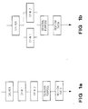
- Fig. 1a and 1b show the options for an SMT production line, i.e. two alternative material flows;
- Fig.2 shows work flow for three different cells;
- Fig.3 shows a method of labelling of the part feeders to facilitate setup;
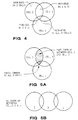
- Figs 4,5A and 5B show how multiple parts can be included in more than one cell;
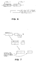
- Fig.6 shows the off-line part storage during production for parts of cells which are not currently in production;
- Fig.7 illustrates the implementation of cells for shop-floor and arranging the parts to improve balance;
- Fig.8A,8B and 8C illustrate adding a board with the greatest contribution to seek a high volume with few new parts, thus demonstrating the "Greedy Board" heuristic;
- Fig.9 illustrates the implementation of cells for shop-floor use and leaving room in cells for adding new boards; and
- Fig.10 is a graph illustrating high-mix SMT line cell definitions with 75% of volume with one setup.
- The equipment set for the line included one Fuji GSP-II stencil machine, two Fuji CP-III high-speed pick-and-place machines (to be arranged either in series with the other machines or in parallel), a Fuji IP-II general-purpose pick-and-place machine, and a Vitronics infrared solder reflow oven. A preliminary analysis of demand on each of these machines and their respective capacities revealed that the bottleneck process would be the two CP-IIIs, regardless of the arrangement of the two machines, and subsequent efforts focused on developing a plan for the use of those machines. Figure 1a and 1b show the two material flows considered.
- One aspect of the CP-IIIs that makes them the bottleneck is that it takes a long time to set up new parts on the machine when changing from batch to batch. Each machine holds about 100 parts (part capacity is a function of individual part sizes, which are variable). Yet the site supports hundreds of parts more than the capacity of the machines, making it impossible to put all parts on line, even with the machines in series. Between any two batches, there would be dozens of CP-III parts to set up.
- In the absence of a clever setup reduction scheme, the expected average parts setup time from one run to the next would be about 60 minutes. By comparison, actual run times for average boards at the site are about four minutes. Thus, for a typical run of ten boards, the run would consist of 60% setup and 40% running time on a CP-III. With equipment costs as high as they are, this sort of machine utilization was unacceptable.
- For this SMT line design, the definition of a cell is simply a group of products that can be built with a single part setup on the CP-IIIs. With SMT boards it is important not to have solder-stencilled boards sitting for longer than about thirty minutes before reflow, so it is essential that boards be completed with only one pass through the machines, an additional constraint faced in this situation. All CP-III parts must be set up for all boards in the cell.
- Another consideration complicating the development of a group technology solution was the flow through the two CP-IIIs. With the two machines in series, most parts could be dedicated allowing more boards in each cell. With the CP-IIIs in parallel, on the other hand, two cells could be set up at a time. Parallel machines were tempting, for it is easier to balance work on them. With series machines, more blocking or starving would be expected, a curse for bottleneck process.
- The parallel arrangement was ultimately rejected for several reasons. First, the stencil printer and the IP-II have significant setup times of their own, and they could not process boards for the two CP-IIIs simultaneously. This would lead to large buffers before and after the CP-III area, violating the goals of low WIP and the cycle times. Also, duplicate setups on two machines (or two setups with high part overlap) would require an undesirable, increased part feeder and inventory cost. Finally, the parallel arrangement would result in a more complicated material flow, presenting more opportunities for errors and confusion.
- With only one line with machines in series, the decision to use a group technology approach implied that temporal cells would be defined, rather than physically separate manufacturing cells. That is, a particular production cell would be set up by placing the appropriate parts on the machines, then all of the boards using that setup would be built before time would be taken to set up the next family of boards. No significant setup to the machine would be required between runs of any two boards in the same cell.
- With multiple cells running on the same line (albeit at different times), the issue of setups between cells remains important. As setups between individual boards in a single cell are nil, it is therefore desirable to have as great a volume of boards as possible in a given cell. This transcends the notion that the greatest number of separate board numbers is key. The proper way to view the problem, from a qualitative point of view, is to reduce as much as possible the expectation that the next board built is in another cell (with another setup). This requires weighting by volume; the greater the demand for a particular board, the more likely it is to appear in the production schedule, especially when multiple, small batches run daily.
- Reducing or eliminating lot-to-lot setups quickly became the key objective of the design process. Since it would be impossible to put all of the parts on line, a process-based solution became imperative. Operating policies based on a group technology approach were the answer.
- Group technology traditionally refers to the manufacture of parts or products grouped together into "families", or "cells", on the basis of similarities between key attributes. The similarities night be a function of the design, the necessary manufacturing processes, or both. The grouping of similar products permits the same tools and fixtures to be used, vastly reducing the time spent setting up each batch. products that have distinctly different characteristics run in another cell on a different machine, or at a different time on the same machines, following a single major setup.
- New products resembling existing products can be introduced with little trouble or expense, but completely new designs that do not fit in an established group might cost more due to increased setups. Thus, the use of clever grouping in manufacturing can reduce costs. Designers can consider the cost of deviating from current designs as they create new products.
- The PCA situation, featuring assembly rather than fabrication, suggests a slightly different approach to the grouping process than the one typically encountered. Most significantly, no complicated, new coding system is required to classify products for sorting into groups as is often used for grouping fabricated parts. Instead, products can be grouped on the basis of common part numbers. At the most rudimentary level, only a list of each board's constituent components is required to divide PCAs into production cells.
- Techniques abound for actually dividing a list of products into production cells. Given a production schedule and a set of physical constraints (like the number of parts that can fit on a machine), it is possible to cast the problem of minimizing setups as a simple mixed-integer linear program. Such formulation to define a single production cell would take this form:
minimize setup time - subject to:
- all components set up for board demand met for all boards machine part capacity not exceeded
- The details of the greedy board heuristic are straightforward. Again, the only data required is the list of part numbers on each board and the expected demand for each board. Specifically, cells are added one at a time by selecting the remaining unassigned boards with the lowest ratio of new parts added to the cell to board volume.
- For this example, consider the following boards with the stated average monthly volumes and constituent components:
appaloosa 1400 E, H, N, P bobcat 132 C, N jaguar 2668 B, D, F, H, N morgan 1100 F, J, M, N ocelot 668 G, H, Q, L puma 1332 B, D, H, N tarzan 900 A, J, K, N current parts in Cell 1: none Board New Parts Volume Ratio appaloosa 4 1400 0.0029 bobcat 2 132 0.0152 jaguar 5 2668 0.0019* morgan 4 1100 0.0036 ocelot 4 668 0.0060 puma 4 1332 0.0030 tarzan 4 900 0.0044 - Jaguar is lowest, so it is the first board added to the cell. It has the highest product volume added per part slot consumed. Jaguar adds five components (B,D,F,H and N); assume that there is a limit of eight parts for the cell for this example.
- For the next board, the ratios change as follows, since B,D,F,H, and N are now already in the cell:
current parts in Cell 1: B, D, F, H, N Board New Parts Volume Ratio appaloosa 2 1400 0.0014 bobcat 1 132 0.0076 morgan 2 1100 0.0018 ocelot 3 668 0.0045 puma 0 1332 0.0000* tarzan 3 900 0.0033 - Now puma has the lowered ratio, since its part set is a complete subset of the parts already in the cell. Since adding puma to the cell does not require the addition of any parts, the parts-to-volume ratios above still apply. The next lowest is appaloosa, which adds two new parts to the cell (E and P). That brings the total number of parts for the cell to seven, still within the physical constraint.
- After adding appaloosa, the part-to-volume ratios for the remaining, unassigned boards become:
current parts in Cell 1: B, D, E, F, H, N, P Board New Parts Volume Ratio bobcat 1 132 0.0076 morgan 2 1100 0.0018 ocelot 3 668 0.0045 tarzan 3 900 0.0033 - Now Morgan has the lowest ratio. However, to add the morgan board requires two new parts in the cell which will not fit. Bobcat is the only board left that will fit, so it is added, even though it has the lowest theoretical contribution. It is only due to the physical constraint on the size of the cell that makes bobcat attractive. Adding bobcat fills
Cell 1, which is made up of parts B,C,D,E,F,H,N, and P. - The second cell is defined by following the same procedure for the remaining boards:
current parts in Cell 2: none Board New Parts Volume Ratio morgan 4 1100 0.0036* ocelot 4 668 0.0060 tarzan 4 900 0.0044 - Morgan is added first. After adding parts F,J,M and N, the following part-to-volume ratios result:
current parts in Cell 2: F,J,M,N Board New Parts Volume Ratio ocelot 4 668 0.0060 tarzan 2 900 0.0022* - Tarzan is added, bringing the total part count to six in the cell (A,F,J,K,M,N). Ocelot still has four parts not in the cell, so it will not fit in
Cell 2 without violating the total part ceiling. It must go inCell 3. Note thatCell 2 is left with two unused part slots, andCell 3 has four unused slots that can be used to accommodate new boards. - The final cell definitions are:
Cell Board Volume Parts 1 5532 B,C,D,E,F,H,N, P 2 2000 A,F,J,K,M, N 3 668 G,H,Q,L -
Cell 1 contains 67% of the total board volume; the volume falls off precipitously with the succeeding cells. Some parts appear in more than one cell. - The greedy board heuristic performs well when high setup costs dominate placement costs. The goal is a list of component part numbers to dedicate on the machines. A cell is defined by adding boards one at a time until the physical machine constraint is reached.
- Thus, the heuristic greedily adds boards to the cell until no more fit. Component part volume is of no consequence. Rather, the volume of boards produced by the cell drives the solution.
- The SMT PCA situation called for the use of the greedy board heuristic because of the time required for setups on the CP-IIIs. The heuristic was used to define one cell at a time, ultimately producing a complete list of cells to run at different times on the same machines. The first pass of the heuristic defined the first cell, filled primarily with the highest volume boards (and other boards with high part overlap). The second and subsequent passes were made after removing the first cell's boards, essentially starting fresh each time but pulling from an increasingly smaller set of boards.
- Many approaches were proposed in the course of applying the greedy board heuristic to the SMT line. The simplest application called for single cells, holding about 200 different parts each, which could be set up as needed. This would result in the largest possible cells, thus reducing the total number of cells required to include all of the shop's boards. However, there would be a major setup every time a switch was made from one cell to the next.
- A feature of the Fuji CP-IIIs is that each machine is actually split into two banks, each holding 50 parts. It is possible with this split-bank feature to run the machine with only one of the banks on line; the other bank can be off line. This permits an operator to work on setting up half the machine while the other bank is busy placing parts on boards. The feature allowed a more refined solution to the problem. The first cell,
Cell 1, was defined so that it would use three of the four available part banks, and it would hold about 150 different parts. Since the first cell defined using the greedy board heuristic contains the highest volume boards, it would be used frequently in the course of a normal production day. To make quick response to demand for one of the high volume boards possible, this cell was kept on line at all tines. That is, the parts inCell 1 were dedicated. - Subsequent cells, holding the lower volume boards and/or boards with relatively little part overlap, have additional parts set up the remaining bank. The 150 parts dedicated to the three CP-III part banks of
Cell 1 would also be available for the boards in the other cells when the fourth bank was put in place, soCells 2 to n could utilize parts from theCell 1 setup plus additional parts from the flexible fourth bank. In practice, the heuristic was used to defineCells 2 to N by first stripping from the material list the parts dedicated inCell 1, since those parts were already guaranteed to be on line. - Figure 2 shows how a day's work might flow through the line.
Cell 1 boards will be built whileCell 2 is being set up. Then, once the setup forCell 2 is complete, current demand for boards in that cell will be produced. Once that demand is satisfied,more Cell 1 boards will run and the next cell will be set up, as demand warrants. Each day a schedule is released of boards necessary to replenish the demand-pull queues. The operator responsible for initiating flow through the line releases boards in groups so that they run together when their respective cells are setup. - Should a situation arise where a significant change to the daily schedule must be accommodated, a board in any cell can be started through the line with a maximum delay of only about an hour. That is the time required to completely tear down one setup on the fourth bank and install another.
Cell 1 boards could be built during the setup time, too. If the change requires building a board inCell 1, which would be the most likely event, then the board could be run immediately, since that cell is always set up. - This approach eliminates the problem of machine idle time during cell setup. Because
Cell 1 has such a large expected volume, boards from that cell can be run through the line while the fourth bank is changed over from one of the smaller cells to the next. There will almost always be sufficient demand forCell 1 boards to fill the time required to execute the setup for the next cell, most of the time, the setup will be completed before theCell 1 boards are completed. This arrangement results in essentially zero expected idle time due to setup for the machine-a far cry from the base case of 60% setup idle time. - Using this approach resulted in the definition of five separate cells for the new line. Results shown in Table 1 reveal that
Cell 1, the cell with the 150 dedicated parts, accounts for the vast majority of the expected work. Roughly speaking,Cell 1 should be running about three quarters of the time, even though it accounts for only about a third of the factory's unique assemblies.TABLE 1: Division of Work Between Cells Cell # unique assemblies assembly volume placements 1 35% 75% 75% 2 35 15 15 3 15 6 7 4 10 4 3 5 5 <1 <1 - The key to success of the group technology approach hinges on the actual implementation on the shop floor. The analysis described so far, while based on realistic data, ignores some practical issues that must be addressed in order to generate a truly workable solution.
- Foremost among the problems encountered in taking the group technology cells from the drawing board to the shop floor was the challenge of balancing work between the two series Cp-IIIs. In practice there will almost always be an imbalance that results in starving the downstream machine of work (when the upstream machine takes longer to process the board) or blocking the upstream machine (when the downstream machine takes longer). Problems with blocking and starving can be mitigated by the use of buffers of work in progress, but the objective was to reduce WIP as much as possible.
- Two further enhancements allowed for better work balance between the CP-IIIs in series. First, work was balanced between the CP-IIIs using another heuristic approach. This heuristic balanced work board by board considering the quantity required of each part number, the time for the machine to place that part type, and specific machine constraints (for example, "tall" parts must be placed on a board last and therefore must always be set up on the second CP-III). The balance was further improved by making a few of the most common parts available on both machines. These components, mostly common resistors and capacitors, occurred in high volume on many boards. In sacrificing a few part slots and putting just a few parts (roughly a half dozen) on each machine, the expected work balance was greatly improved.
- Second, because the general purpose pick-and-place machine (the Ip-II) had unused capacity, parts unique to a single board were moved to the Ip-II. Those parts would have a limited contribution to any production cell, since they would only be used for one board. Parts originally classified as Cp-III parts were reassigned to the IP-II on a board-to-board basis, and the material list used to define the CP-III cells was modified accordingly. Calculations showed that the additional time required to set up the IP-II would not jeopardize the flow, the Cp-IIIs would still be the bottleneck and the IP-II would still have some idle time.
- One of the many concerns that was raised about the implementation of the group technology solution addressed the ability of the operators to accurately set up the cells each tine. In fact, the likelihood of inaccurate setups should be greatly reduced because there are fewer unique setups. With no cells, each assembly has its own setup. The operator is required to carefully sequence part feeders by matching a nondescriptive, multi-character part number. The difficulty of ensuring the proper order, in fact, accounts for much of the time required for a normal setup operation.
- With the introduction of cell-based production, then setup process was greatly simplified. First of all, with cells there are only a few different setups to manage, and the largest,
Cell 1, is fixed in place. Cells 2-5 are defined for the operator using a simple scheme using coloured tape and numbers. The part feeders for each cell set up off line are marked with a different color. Then, the feeders are numbered in the order of their appearance on the CP-III feeder bank. Thus, whenCell 3 is set up, all of the feeders with blue labels should be lined up in numerical order, no other feeders should have blue labels. With this practice in place, the difficult setup requiring matching of the part codes is eliminated. Simple visual cues indicate quickly that the machine is ready to run. The simplicity of this approach leads to higher quality products, as there are fewer defects attributable to setup errors. - Figure 3 shows how the different component parts constituting each cell are coded for easy identification by the operators. Figure 4 shows how multiple parts can be included in more than one cell. When one cell is set up, all other parts are in an off-line storage area. Note that
Cell 2 ∩Cell 3 might be equal to zero. More generally, Cn ∩ Cm = 0 can be true. Figs 5A and 5B show alternative situations in which a plurality of parts can be included in more than one cell. In Fig.5A there is a high overlap (corresponding to many parts) betweencells - As new boards are added and old boards drop off in volume, the performance of the system degrades. The load balancing between the two machines deteriorates. Also, some of the ostensibly low-volume cells (Cells 2-5) might be run more and more often as demand increases for boards in those cells. Redefining the cells is thus a natural part of running the SMT line. Each redefinition requires the generation of new pattern files, and the labels on the part feeders have to be redone. With an automated system, cells are examined and rebalanced every few weeks. This keeps changes to a minimum, favouring frequent, minor changes over infrequent but substantial changes. Newly introduced products are also handled in this way, and the changes keep cell alignment and part balance close to optimal. Feeder relabelling to redefine cells is timed to coincide with preventive maintenance of the machines.
- The principal advantage of the group technology approach with the use of the Fuji split bank feature is bringing batch setup times close to zero. Along with this obvious, quantifiable improvement in operating efficiency (machines running close to 100% of the time), there are many qualitative advantages to the solution.
- First, with no machine setup required between board types within a cell, batch size is not an issue. Low-volume boards can run in very small batches, as small as the other process steps can accommodate. This allows a demand-pull strategy and avoids building to stock. The line can build in any quantities needed.
- The group technology solution also has a positive effect on quality. Since the parts for 75% of the board volume (Cell 1) are dedicated to machine slots, those boards do not suffer defects due to errors in part set up. For the remaining 25% of the board volume falling into other cells, the part set up is so simplified due to colored tape labelling that set up errors are virtually eliminated. Since many small SMT parts are unmarked by the vendor, defects due to part set up errors cannot be detected visually and are not found until the test step at the end of the process. By the time an error is discovered, a number of boards may have been produced, generating a great deal of repair work. Thus, eliminating or reducing set up errors has a significant impact on both quality and the anticipated cost of repair.
- Another advantage of this approach is a reduction in the number of production personnel required to run the line. Since part setups occur on only one CP-III, a single operator can run both CP-III's.
- Finally, this solution allows for growth as volumes and numbers of board types increase. As the capacity of the first line is reached, a second line with the same configuration will be installed. This second line will be given a different set of cells, with many boards fitting cells on both lines to allow for load balancing.
- The group technology approach incorporating the use of the split bank feature to take cell set ups off-line met all of the goals for a process design. The goal of flexibility to build any board in any quantity as requested by the demand-pull system was net by the virtual elimination of batch setup tine. Overall system cost was reduced by increasing line efficiency (run time approaching 100%). Savings are also attributed to reduced finished goods inventories, reduced defects, and reduced production personnel. Finally, the series configuration provides a smooth, linear flow, minimizing queuing on the line. This flow keeps levels of WIP and cycle time as low as possible.
- While the examples cited here demonstrate the success of group technology at SMT line design, the ideas can be easily applied to other printed circuit board assembly production areas. Similar advantages can,be expected in through-hole assembly shops and shops with mixed technologies.
Claims (6)
- A method of assembling components on a plurality of circuit board assemblies, wherein the assemblies collectively require a greater number of different components than can be accomodated at the same time by a production apparatus, said apparatus having multiple component banks, the method including the steps of:a) choosing a first family of circuit board assemblies by:i) choosing a first circuit board assembly out of the plurality of circuit board assemblies, which has the lowest ratio of number of different components required to be placed on a circuit board of that assembly to the volume of circuit boards in that assembly;ii) subsequently choosing another circuit board assembly out of the remaining circuit board assemblies, having the lowest ratio of number of different components required to be placed on a circuit board of that assembly, reduced by the number of different components already required for a previously chosen circuit board assembly, to the volume of the circuit boards in that assembly; andiii) repeating step (ii), choosing further circuit board assemblies as long as the total number of different components required does not exceed the capacity of a predetermined number of component banks of the production apparatus;b) setting up the production apparatus by loading the components for the first family of circuit board assemblies into the predetermined number of component banks;c) running the production apparatus to place the components for the first family of circuit board assemblies into their installation position on the circuit boards;d) selecting a second family of circuit board assemblies by carrying out the step (a) with respect to circuit board assemblies not included in the first family and with respect to the remaining component banks of the production apparatus;e) setting up the production apparatus by loading the components for the second family of circuit board assemblies into the remaining component banks of the production apparatus; andf) running the production apparatus, after completing the latter setting up step (e), to place the components for the second family of circuit board assemblies into their installation position on the circuit boards.
- The method according to Claim 1, wherein the production apparatus includes two separate production machines (CP-III 1, CP-III 2) in series, resulting in said predetermined number of component banks available for the first family being higher.
- The method according to Claim 2, wherein the two separate production machines used in said running steps include some common components.
- The method according to any preceding claim, including visually coding the components required in step a) of Claim 1.
- The method according to any preceding claim, including visually coding the components required in step d) of Claim 1.
- The method according to any preceding claim, wherein steps d) and e) of Claim 1 are carried out during step c) of Claim 1.
Applications Claiming Priority (2)
| Application Number | Priority Date | Filing Date | Title |
|---|---|---|---|
| US07/589,748 US5170554A (en) | 1990-09-28 | 1990-09-28 | High mix printed circuit assembly technique |
| US589748 | 1990-09-28 |
Publications (2)
| Publication Number | Publication Date |
|---|---|
| EP0478360A1 EP0478360A1 (en) | 1992-04-01 |
| EP0478360B1 true EP0478360B1 (en) | 1996-07-17 |
Family
ID=24359351
Family Applications (1)
| Application Number | Title | Priority Date | Filing Date |
|---|---|---|---|
| EP91308847A Expired - Lifetime EP0478360B1 (en) | 1990-09-28 | 1991-09-27 | High mix printed circuit assembly technique |
Country Status (6)
| Country | Link |
|---|---|
| US (1) | US5170554A (en) |
| EP (1) | EP0478360B1 (en) |
| JP (1) | JPH04246897A (en) |
| KR (1) | KR930007321A (en) |
| DE (1) | DE69120887T2 (en) |
| HK (1) | HK33297A (en) |
Families Citing this family (32)
| Publication number | Priority date | Publication date | Assignee | Title |
|---|---|---|---|---|
| US5258915A (en) * | 1990-09-28 | 1993-11-02 | Hewlett-Packard Company | System and method for optimum operation assignments in printed circuit board manufacturing |
| US5325305A (en) * | 1992-07-24 | 1994-06-28 | The Boeing Company | Automated setup verification system |
| DE19502434A1 (en) * | 1994-04-29 | 1995-11-02 | Hewlett Packard Co | System and method for incrementally manufacturing circuit boards |
| JP3552806B2 (en) * | 1995-09-13 | 2004-08-11 | 松下電器産業株式会社 | Component mounting method |
| MX9709038A (en) | 1996-11-25 | 1998-08-30 | Samsung Electronics Co Ltd | System and method of production of printed circuit board assemblies. |
| WO1998049646A2 (en) * | 1997-05-01 | 1998-11-05 | Motorola Inc. | Dynamically reconfigurable assembly line for electronic products |
| KR100369401B1 (en) * | 2000-04-03 | 2003-01-29 | (주) 이우티이씨 | System for detecting a pipe under ground using magnetic field |
| DE10023358A1 (en) * | 2000-05-12 | 2001-11-29 | Siemens Ag | Production line for one-sided and double-sided assembly of printed circuit boards |
| JP2003030250A (en) * | 2001-07-12 | 2003-01-31 | Oki Electric Ind Co Ltd | System for estimating printed board design man-hour and estimation program |
| US6829514B2 (en) * | 2003-01-17 | 2004-12-07 | Motorola, Inc. | Balancing workloads in an electronics assembly factory |
| US7457128B2 (en) * | 2005-07-22 | 2008-11-25 | Hewlett-Packard Development Company, L.P. | Flexible cell configuration for multi-processor systems |
| DE102009013353B3 (en) * | 2009-03-16 | 2010-10-07 | Siemens Aktiengesellschaft | Method for determining armor for constant tables of placement machines |
| DE102012211810A1 (en) * | 2012-07-06 | 2014-02-20 | Siemens Aktiengesellschaft | Formation of setup families on assembly lines |
| US9974220B2 (en) * | 2012-07-06 | 2018-05-15 | Siemens Aktiengesellschaft | Method for fitting printed circuit boards with components |
| CN104412733B (en) * | 2012-07-06 | 2016-11-09 | 西门子公司 | Wiring harness plate is with the method and apparatus to circuit board assembling electronic component |
| US9888620B2 (en) | 2012-07-06 | 2018-02-06 | Siemens Aktiengesellschaft | Allocation of printed circuit boards on fitting lines |
| DE102012221258A1 (en) * | 2012-11-21 | 2014-05-22 | Siemens Aktiengesellschaft | Optimization of setup families |
| WO2016021042A1 (en) * | 2014-08-08 | 2016-02-11 | 富士機械製造株式会社 | Substrate production method and substrate production condition determination method |
| DE102014222940A1 (en) | 2014-11-11 | 2016-05-12 | Siemens Aktiengesellschaft | Assembly of printed circuit boards |
| DE102014222936A1 (en) * | 2014-11-11 | 2016-05-12 | Siemens Aktiengesellschaft | Assembly of printed circuit boards |
| DE102014225713A1 (en) * | 2014-12-12 | 2016-06-16 | Siemens Aktiengesellschaft | Method and system for assembling printed circuit boards and computer program product for carrying out the method |
| DE102015200420A1 (en) | 2015-01-14 | 2016-07-14 | Siemens Aktiengesellschaft | Method and system for assembling printed circuit boards |
| DE102015200414A1 (en) * | 2015-01-14 | 2016-07-14 | Siemens Aktiengesellschaft | Method and system for assembling printed circuit boards |
| CN107409491B (en) * | 2015-03-05 | 2020-04-24 | 株式会社富士 | Installation management device |
| DE102015206741A1 (en) * | 2015-04-15 | 2016-10-20 | Siemens Aktiengesellschaft | Formation of set-up families for a machining system with a machine tool |
| CN105072813A (en) * | 2015-08-13 | 2015-11-18 | 广州杰赛科技股份有限公司 | Printed board combination production method |
| JP6748718B2 (en) * | 2016-07-08 | 2020-09-02 | 株式会社Fuji | Production planning system and production planning method |
| EP3474650B1 (en) * | 2017-10-19 | 2020-12-09 | Sick Ag | Method for producing a retrofitting set for an assembly machine |
| KR102155013B1 (en) * | 2018-02-27 | 2020-09-14 | 한화정밀기계 주식회사 | Feeder arrangement method for multi-PCB single-mounter with multiple feeder base |
| US10657297B2 (en) * | 2018-06-01 | 2020-05-19 | Mentor Graphics Corporation | Part number consolidation in printed circuit board assembly design |
| EP3897087A4 (en) * | 2018-12-11 | 2021-12-15 | Fuji Corporation | Mounting system and method of arranging component feeding units |
| EP4231800A1 (en) * | 2022-02-22 | 2023-08-23 | Siemens Aktiengesellschaft | Computer-implemented method for determining a set of module types of a predetermined set of module types and an associated modified fixed setup |
Family Cites Families (4)
| Publication number | Priority date | Publication date | Assignee | Title |
|---|---|---|---|---|
| US4651863A (en) * | 1983-08-31 | 1987-03-24 | Westinghouse Electric Corp. | System for assembling electronic component kits |
| JPH0668696B2 (en) * | 1985-02-22 | 1994-08-31 | 株式会社日立製作所 | NC data creation method for inserter |
| US4694570A (en) * | 1985-11-21 | 1987-09-22 | Amistar Corporation | Surface mounted component transport mechanism |
| NL8900027A (en) * | 1989-01-06 | 1990-08-01 | Philips Nv | METHOD AND APPARATUS FOR PLACING COMPONENTS ON A CARRIER. |
-
1990
- 1990-09-28 US US07/589,748 patent/US5170554A/en not_active Expired - Lifetime
-
1991
- 1991-09-27 DE DE69120887T patent/DE69120887T2/en not_active Expired - Fee Related
- 1991-09-27 EP EP91308847A patent/EP0478360B1/en not_active Expired - Lifetime
- 1991-09-27 KR KR1019910016916A patent/KR930007321A/en not_active Application Discontinuation
- 1991-09-30 JP JP3251647A patent/JPH04246897A/en active Pending
-
1997
- 1997-03-20 HK HK33297A patent/HK33297A/en not_active IP Right Cessation
Also Published As
| Publication number | Publication date |
|---|---|
| HK33297A (en) | 1997-03-27 |
| US5170554A (en) | 1992-12-15 |
| DE69120887D1 (en) | 1996-08-22 |
| JPH04246897A (en) | 1992-09-02 |
| KR930007321A (en) | 1993-04-22 |
| EP0478360A1 (en) | 1992-04-01 |
| DE69120887T2 (en) | 1996-11-28 |
Similar Documents
| Publication | Publication Date | Title |
|---|---|---|
| EP0478360B1 (en) | High mix printed circuit assembly technique | |
| CA2038939C (en) | Production control system | |
| JPH09282374A (en) | Mounting factory management support system | |
| US5745972A (en) | Method of producing parts/substrate assemblies | |
| EP0843513B1 (en) | Facility operating method | |
| CN114585982A (en) | Configuration support method, learning completion model generation method, program, configuration support system, and operating system | |
| Ji et al. | Planning for printed circuit board assembly: the state-of-the-art review | |
| JPH10229293A (en) | Part mounting program forming method | |
| US5371940A (en) | Pallet arranging system | |
| JP2001251095A (en) | Manufacture control system | |
| Davis et al. | Group technology for high-mix printed circuit assembly | |
| Hillier et al. | Optimal component assignment and board grouping in printed circuit board manufacturing | |
| Bhatnagar et al. | Order release and product mix coordination in a complex PCB manufacturing line with batch processors | |
| Smed et al. | Techniques and applications of production planning in electronics manufacturing systems | |
| Neammanee et al. | Integrated methodology for board assignment and component allocation in printed circuit board assembly | |
| Yilmaz et al. | Simulation of mixed-model PCB assembly lines with group setup and bypass conveyors | |
| JPH0754879B2 (en) | Printed circuit board assembly production method | |
| Ahmadi | A hierarchical approach to design, planning, and control problems in electronic circuit card manufacturing | |
| WILHELM | Material flow management in cellular configurations for small-lot, circuit card assembly | |
| JPH06310898A (en) | Parts mount design equipment | |
| JPH04346500A (en) | Pallet formation system | |
| Dillon et al. | PCB assembly line setup optimization using component commonality matrices | |
| Ahmadi et al. | Design of electronic assembly lines: An analytical framework and its application | |
| Jadhav et al. | Analyzing printed circuit board assembly lines using a PCB assembly template | |
| Albano et al. | Manufacturing execution: circuit packs |
Legal Events
| Date | Code | Title | Description |
|---|---|---|---|
| PUAI | Public reference made under article 153(3) epc to a published international application that has entered the european phase |
Free format text: ORIGINAL CODE: 0009012 |
|
| AK | Designated contracting states |
Kind code of ref document: A1 Designated state(s): DE FR GB |
|
| 17P | Request for examination filed |
Effective date: 19920904 |
|
| 17Q | First examination report despatched |
Effective date: 19941208 |
|
| GRAH | Despatch of communication of intention to grant a patent |
Free format text: ORIGINAL CODE: EPIDOS IGRA |
|
| GRAH | Despatch of communication of intention to grant a patent |
Free format text: ORIGINAL CODE: EPIDOS IGRA |
|
| GRAA | (expected) grant |
Free format text: ORIGINAL CODE: 0009210 |
|
| AK | Designated contracting states |
Kind code of ref document: B1 Designated state(s): DE FR GB |
|
| REF | Corresponds to: |
Ref document number: 69120887 Country of ref document: DE Date of ref document: 19960822 |
|
| ET | Fr: translation filed | ||
| PLBE | No opposition filed within time limit |
Free format text: ORIGINAL CODE: 0009261 |
|
| STAA | Information on the status of an ep patent application or granted ep patent |
Free format text: STATUS: NO OPPOSITION FILED WITHIN TIME LIMIT |
|
| 26N | No opposition filed | ||
| REG | Reference to a national code |
Ref country code: GB Ref legal event code: 732E |
|
| REG | Reference to a national code |
Ref country code: GB Ref legal event code: IF02 |
|
| REG | Reference to a national code |
Ref country code: FR Ref legal event code: TP |
|
| PGFP | Annual fee paid to national office [announced via postgrant information from national office to epo] |
Ref country code: FR Payment date: 20060918 Year of fee payment: 16 |
|
| PGFP | Annual fee paid to national office [announced via postgrant information from national office to epo] |
Ref country code: GB Payment date: 20060925 Year of fee payment: 16 |
|
| PGFP | Annual fee paid to national office [announced via postgrant information from national office to epo] |
Ref country code: DE Payment date: 20061031 Year of fee payment: 16 |
|
| GBPC | Gb: european patent ceased through non-payment of renewal fee |
Effective date: 20070927 |
|
| PG25 | Lapsed in a contracting state [announced via postgrant information from national office to epo] |
Ref country code: DE Free format text: LAPSE BECAUSE OF NON-PAYMENT OF DUE FEES Effective date: 20080401 |
|
| REG | Reference to a national code |
Ref country code: FR Ref legal event code: ST Effective date: 20080531 |
|
| PG25 | Lapsed in a contracting state [announced via postgrant information from national office to epo] |
Ref country code: FR Free format text: LAPSE BECAUSE OF NON-PAYMENT OF DUE FEES Effective date: 20071001 |
|
| PG25 | Lapsed in a contracting state [announced via postgrant information from national office to epo] |
Ref country code: GB Free format text: LAPSE BECAUSE OF NON-PAYMENT OF DUE FEES Effective date: 20070927 |