EP0477712B1 - Méthode et dispositif pour l'amélioration des bords dans des dispositifs à matrice de points - Google Patents
Méthode et dispositif pour l'amélioration des bords dans des dispositifs à matrice de points Download PDFInfo
- Publication number
- EP0477712B1 EP0477712B1 EP91115671A EP91115671A EP0477712B1 EP 0477712 B1 EP0477712 B1 EP 0477712B1 EP 91115671 A EP91115671 A EP 91115671A EP 91115671 A EP91115671 A EP 91115671A EP 0477712 B1 EP0477712 B1 EP 0477712B1
- Authority
- EP
- European Patent Office
- Prior art keywords
- bits
- matrix
- bit
- edge
- segment
- Prior art date
- Legal status (The legal status is an assumption and is not a legal conclusion. Google has not performed a legal analysis and makes no representation as to the accuracy of the status listed.)
- Expired - Lifetime
Links
Images


Classifications
-
- G—PHYSICS
- G09—EDUCATION; CRYPTOGRAPHY; DISPLAY; ADVERTISING; SEALS
- G09G—ARRANGEMENTS OR CIRCUITS FOR CONTROL OF INDICATING DEVICES USING STATIC MEANS TO PRESENT VARIABLE INFORMATION
- G09G3/00—Control arrangements or circuits, of interest only in connection with visual indicators other than cathode-ray tubes
-
- G—PHYSICS
- G06—COMPUTING; CALCULATING OR COUNTING
- G06K—GRAPHICAL DATA READING; PRESENTATION OF DATA; RECORD CARRIERS; HANDLING RECORD CARRIERS
- G06K15/00—Arrangements for producing a permanent visual presentation of the output data, e.g. computer output printers
- G06K15/02—Arrangements for producing a permanent visual presentation of the output data, e.g. computer output printers using printers
- G06K15/12—Arrangements for producing a permanent visual presentation of the output data, e.g. computer output printers using printers by photographic printing, e.g. by laser printers
- G06K15/128—Arrangements for producing a permanent visual presentation of the output data, e.g. computer output printers using printers by photographic printing, e.g. by laser printers generating or processing printable items, e.g. characters
-
- G—PHYSICS
- G06—COMPUTING; CALCULATING OR COUNTING
- G06K—GRAPHICAL DATA READING; PRESENTATION OF DATA; RECORD CARRIERS; HANDLING RECORD CARRIERS
- G06K15/00—Arrangements for producing a permanent visual presentation of the output data, e.g. computer output printers
- G06K15/02—Arrangements for producing a permanent visual presentation of the output data, e.g. computer output printers using printers
- G06K15/12—Arrangements for producing a permanent visual presentation of the output data, e.g. computer output printers using printers by photographic printing, e.g. by laser printers
-
- G—PHYSICS
- G09—EDUCATION; CRYPTOGRAPHY; DISPLAY; ADVERTISING; SEALS
- G09G—ARRANGEMENTS OR CIRCUITS FOR CONTROL OF INDICATING DEVICES USING STATIC MEANS TO PRESENT VARIABLE INFORMATION
- G09G5/00—Control arrangements or circuits for visual indicators common to cathode-ray tube indicators and other visual indicators
- G09G5/20—Function-generator circuits, e.g. circle generators line or curve smoothing circuits
-
- G—PHYSICS
- G06—COMPUTING; CALCULATING OR COUNTING
- G06K—GRAPHICAL DATA READING; PRESENTATION OF DATA; RECORD CARRIERS; HANDLING RECORD CARRIERS
- G06K2215/00—Arrangements for producing a permanent visual presentation of the output data
- G06K2215/0002—Handling the output data
- G06K2215/004—Generic data transformation
- G06K2215/006—Anti-aliasing raster data
-
- G—PHYSICS
- G06—COMPUTING; CALCULATING OR COUNTING
- G06K—GRAPHICAL DATA READING; PRESENTATION OF DATA; RECORD CARRIERS; HANDLING RECORD CARRIERS
- G06K2215/00—Arrangements for producing a permanent visual presentation of the output data
- G06K2215/0002—Handling the output data
- G06K2215/0062—Handling the output data combining generic and host data, e.g. filling a raster
- G06K2215/0071—Post-treatment of the composed image, e.g. compression, rotation
Definitions
- the present invention relates to a method for enhancing the displayed image of a print or display apparatus as defined in the preamble of claim 1.
- the invention further, relates to an apparatus for enhancing the output of a print or display device which produces a digitized image in dot matrix format as defined in the preamble of claim 8.
- the field of this invention relates generally to apparatus and methods for controlling dot matrix output devices, such as cathode ray tubes and dot printing devices, to enhance edge representation when an image of an object is converted from graphical/mathematical format to display or print device format (a series of dots/pixels). More particularly, the present invention is directed to an improved implementation of weighted gradient work theory used to provide image edge transition smoothing in an efficient real time image enhancement system.
- the approximated appearance can be enhanced by locating the jagged edge segments and correcting the segment transition, or by increasing the device resolution to minimize the visual distortion to the degree that the naked eye cannot differentiate the transition.
- increasing device resolution requires larger memory storage for the bitmap representation. The extra cost incurred by the memory is not desirable for general commercial products.
- Document US-A-4 321 610 discloses a technique which utilizes a half-dot character memory matrix and a shift register to enhance edges by coupling a half dot with an edge dot. This method at best enhances the resolution by a factor of two at the expense of extra memory storage and emboldening result.
- Document EP-A 0 199 502 discloses a method and apparatus for improving the quality of an image produced by a raster display device.
- the prior art method forms an image by a plurality of pixels and comprises modifying the intensity of selected pixels in the image so as to tend to smooth an edge of the image.
- a plurality of arrays of pixels is selected from the pixels forming at least one edge of the image the quality of which is to be improved.
- the pattern of the pixels in each array is compared with a stored set of patterns, each of which representing a pattern of pixels forming at least one edge of an image.
- the method is associated with rules relating to modifying the intensity of at least one pixel of the pattern, so as to determine a matching pattern for each array.
- the intensity of at least one pixel of each array is modified in accordance with the rules relating to the matching stored pattern.
- weighted gradient mask matrices are applied to identify segments of an object by detecting changes in brightness. Due to the nature of complex matrix multiplication, this approach has in the past been used for remote usage for military or research purposes where computation power is sufficient and time is not a concern, but never in real time applications where segment recognition and modification need to be accomplished before the next pixel is displayed or printed.
- a simplified formula can be implemented to use weighted gradient mask matrices to enhance the output of an electrophotographic printing machine or computer monitor display. Thus logical computation can be performed in the place of addition and multiplication to reduce the time required.
- this object is achieved by the subject-matter of the characterizing portion of claim 1.
- th object is achieved by the subject-matter of the characterizing portion of claim 8.
- the present invention therefore, provides a technique to detect the presence of edges, and then to determine if the detected edge is part of a segment transition. Based on the finding, the edge is modified either by repositioning related dots, or by altering the dot size.
- a group of gradient mask matrices are applied to a "current matrix", wherein a TBAP (To Be Adjusted Pixel) is surrounded by neighboring pixels, to determine if the TBAP is at a location where a change of brightness occurs. From this matrix operation, a conclusion is derived as to the existance or non-existance of an edge nd the direction of the brightness change. The current matrix and a predetermined number of previously evaluated and yet to be evaluated pixels are then compared to a set of reference bit patterns which depict possible segment changes to be corrected. If the result indicates that the TBAP is on an edge of a changing edge segment, a corresponding code will be generated to modify the TBAP to enhance the smoothness of a segment transition.
- TBAP To Be Adjusted Pixel
- the specific code will change either the location or the size of the TBAP; whereas in the case of a monochrome screen display, the specific code will change the intensity of the TBAP.
- the altered segment transition is caused to appear less jagged than the unaltered representation.
- This weighted gradient mask matrix approach preserves the integrity of image outlines and font design while improving the visual representation of all edges.
- the derived matrix operation uses AND and INVERTER logic for the matrix convolution process to eliminate CPU-intensive addition and multiplication calculations. Therefore, a system utilizing the present invention can achieve higher output quality in real time applications.
- the present circuitry design provides a number of modulation registers for electrophotographic engine-specific, pulse-width/dot-size relationship.
- the present circuitry can also support an external ROM (Read Only Memory) or PAL (Programmable Array Logic) device to store additional information for fine-tuning the adjustments to be made in individual output devices.
- ROM Read Only Memory
- PAL Programmable Array Logic
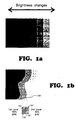
- Fig. 1a illustrates a typical change in brightness and its visual effect.
- Fig. 1b illustrates the definition of an "edge" as a point in space where its value of brightness differs from its neighboring point.
- Fig. 2a is a diagram illustrating a prior art bitmap representation of an area after a "grid fitting" process.
- the round darker dots represent pixels that are turned “ON”, whereas the lighter shaded area illustrates the brightness change as perceived by the human eye.
- Fig. 2b is a diagram illustrating the bitmap representation of Fig. 2a after edge enhancement in accordance with the present invention. Dots ranging from 50% - 80% which were turned “ON” as full dots in Fig. 2a, are now adjusted to enhance the smoother representation of the edge. The 30% dot, which in Fig 2a was not an "ON" pixel, is now adjusted to enhance the edge.
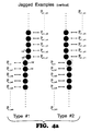
- Fig. 3a outlines 4 possible slopes of defined "segments" in digital applications.
- Fig. 3b illustrates an example of an object composed of a plurality of edge segments 1-10.
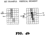
- Fig. 4a is a diagram showing the mathematical definition of a "vertical edge segment" as used in the present invention.
- Fig. 4b shows an example of an unmodified step transition if a vertical edge segment and a corresponding edge-enhanced vertical segment.
- Figs. 5a and 5b are diagrams illustrating "horizontal segments" as contrasted with the vertical examples depicted in Figs. 4a and 4b.
- Fig. 6 illustrates how laser beam pulse manipulation can yield various results in a single pixel.
- Fig. 7a illustrates the Gradient Mask convolution concept and the general formula applied in gradient mask matrix operation.
- Fig. 7b illustrates the simplified, derived format of the weighted gradient mask, and the rules used in the present invention for edge detection.
- Figs. 8a and 8b are examples of how the rules and formula are applied, and the results of derivation.
- Fig. 9a is a block diagram illustrating the major building blocks of a laser printer controller.
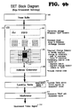
- Fig. 9b is a block diagram illustrating the data flow within the circuitry and its associated components.
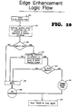
- Fig. 10 is a logic flow chart depicting the segment detection and decision making process.
- Fig. 11 shows an example of segment detection by examining the past and future trend of the current edge.
- Fig. 12 is a chip design block diagram showing the relationship of edge enhancement circuitry and signals.
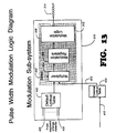
- Fig. 13 shows the modulized structure within the circuitry design to support multiple output devices.
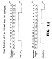
- Figs. 14 and 15 illustrate an example of how the present invention preserves the unique property of an individual electrophotographic printing machine under the general formula.
- the present invention can be applied to various dot matrix devices, such as cathode ray tubes, electrophotographic printing machines, etc., to enhance the edge smoothness of the images generated or reproduced thereby.
- dot matrix devices such as cathode ray tubes, electrophotographic printing machines, etc.
- the particular apparatus described herein is an application specific integrated circuit (ASIC) for laser printers, realized by implementing the present invention.
- ASIC application specific integrated circuit
- the invention can be adapted for use in other dot matrix devices to enhance edge appearance using the same technique.
- Dot matrix devices produce output in bitmap formats to be displayed on a CRT or printed on paper or other hard media.
- a certain degree of loss in precision is inevitable.
- further data loss is introduced. Therefore, visible distortion in the final representation is normally found across the spectrum of the various types of low to medium resolution devices. Typically, the distortion is most obvious near edge transitions, where brightness changes from one level to the other.
- Fig. 1a shows one example of an area including transitions between eight different shades. Looking briefly at this image, one will note that the eyes pay more attention to the edges where shades change than to any difference in shade.
- Fig. 1b a small square area 100 of a changing edge is enlarged to illustrate the edge 101 demarking a transition from a 30% gray level region 102 to a 50% gray level region 104.
- the small squares represent the device grids (pixels) with the ideal edge 101 passed through.
- An objective of the present invention is to adjust the final output, with all device limitations taken into consideration, so the near ideal edges are reproduced.
- a dark object with a left edge inclined at an angle near 45° will be placed in the device frame to be displayed or printed, as shown in Fig. 2a.
- the actual, or ideal, edge 112 of this object is distorted in the process of bitmap conversion. More specifically, a pixel that has 50% or more of its area covered by the dark object is determined to be an "ON" bit, as depicted at 110 for example. However, a pixel having less than 50% of its area covered by the object is identified as an "OFF" bit, as depicted at 111. Thus, a printout or display of this representation forms a jagged edge rather than the straight edge 112.
- the lighter shaded area 116 in Fig. 2a represents the resulting shape of the object as perceived by the human eye.
- the present invention enhances the edge representation so that it appears substantially less jagged as depicted in Fig. 2b.
- the jagged edge in Fig. 2a is adjusted by the insertion or substitution of various smaller dot sizes 122 to smooth the edge.
- the dotted lines 120 in Fig. 2b indicate where a full dot in Fig. 2a is now shrunk to a smaller size dot 122, and a 30% dot 124 is added to pad the area which normally would not have been an ON pixel.
- the adjustable dot size of the present invention can vary from 1/2 to 1/32 of a full dot. By varying the dot size to enhance edges, as indicated at 128, a smoother edge representation can be achieved.
- an edge segment is defined as a series of adjacent, aligned dots which collectively define a line having the same slope.
- segments in a digital system 90°, 0°, -45°, and 45°, as depicted in Fig. 3a. Any other slopes can not be represented perfectly in digital format without staircase distortion.
- Fig. 3b shows a contour which is composed of 10 segments 1-10.
- Fig. 4a two types of transitions between segments are illustrated. Each type includes two vertically disposed but laterally displaced segments. Pixel dots P x, y+1 130 and P x, y 132 of Fig. 4a belong to the same 90° segment. Pixel dots P x+1, y-1 134 and P x+1, y-2 136 are likewise two pixels of a 5 dot segment. P x,y 132 and P x+1, y-1 134 form a segment change.
- a dot matrix device In a dot matrix device, all edges can be broken down into segments. One segment can comprise any number of dots.
- Fig. 4a type #1 is a near straight vertical line. The mathematical model to represent the line is:
- Fig. 4a type #2 represents the other possible vertical segment transition, which can be expressed as:
- V1 ⁇ VL1(N,M)
- V2 ⁇ VL2(N,M)
- H1 ⁇ HL1(N,M)
- H2 ⁇ HL2(N,M)
- N and M determine the pixel input capacity of sampling circuit. In order to use the present invention in a real time application, N and M can not be too large.
- Fig. 3b will be used as a reference.
- SEG(m-n) indicate the transition from an arbitrary segment #m to segment #n.
- the jagged SEG(5-6), SEG(7-8), and SEG(8-9) of Fig. 3b must be smoothed, while SEG(1-2), SEG(4-5) and SEG(6-7) are left alone.
- SEG(2-3), SEG(3-4), SEG(9-10), and SEG(10-1) are optional to the implementation.
- the above equations can be applied to detect these segment changes with some appropriate N and M values.
- an Edge Enhancement Sensor (EES), to be further described below, is implemented to locate and improve edges.
- EES Edge Enhancement Sensor
- SCD Segment Change Detector
- a segment change is detected and this change is determined to be an effective change, such as SEG(5-6) in Fig. 3b, then an appropriate modulation signal will be generated to modify the TBAP by changing its width, height, or both.
- the TBAP 140 is on the edge of a changing segment. It is thus replaced by three 1/4 subdots 141 and coupled with another 1/4 subdot 142 for its adjacent pixel. Therefore, to the human eye, a full size dot appears to be shifted to the right a distance equal to 1/4 of a regular pixel width.
- Figs. 5a and 5b illustrate the horizontal example of segment detection and edge enhancement.
- the TBAP 160 is modified to provide a 75% dot visual effect with one full pixel width and smaller height.
- pulse width modulation can be used to modify the width of a pixel dot, as illustrated at 167 in Fig. 6, to achieve a flatter dot in a laser printer
- two signal pulses 166 which in combination give the desired energy level are used in the place of one pixel signal.
- two smaller dots 164 overlapping each other create the illusion of a single flat dot 165.
- the two narrow pulses 166 not only shrink the width of each dot 164 but also the height thereof. However, if the energy level peaks through the threshold, a shorter than full width pulse 169 still yields the full height dot 168.
- a Gradient Mask is an axb matrix wherein a and b are integers and particular weights are given to a pre-determined matrix of bit cells, so that a particular type of gradient change can be identified. Gradient changes introduce edges. Thus the present invention is applied to enhance edges.
- the mathematical way to apply a weighted gradient mask 174 (Fig. 7a) to a particular matrix or bitmap pattern 172 is not the standard matrix operation. Instead, the two matrices are convolved by a convolution operator as described in Fig. 7a. Specifically, the value of each cell in the first matrix is multiplied by the value of the cell in the same location of the second matrix. The sum of the multiplications then yields a value which can be used to determine the direction of the gradient.
- the entries for each cell of the subject matrix can be numbers that represent different colors, intensities, or gray shades.
- the entries for the cells of the gradient masks are numbers which carry different weights to distinguish various gradients.
- an ASIC application specific integrated circuit
- black and white are two discrete levels and there is nothing inbetween, 1 and 0 are respectively used to represent a black, or "ON", pixel and a white, or "OFF", pixel.
- a new weighted gradient mask operation is derived to use boolean operations as illustrated in Fig. 7b.
- the calculations are narrowed down to just boolean AND and NOT operations as expressed at 188 to extract the gradient features that used to be used in the standard convolution methodology.
- the circuitry is also simplified. The result is that the method in the present invention can now be implemented in real time applications which were previously considered inapplicable in prior art systems.
- segment condition of the current pattern 172 (a 3 x 3 pixel matrix) to be determined is convolved with a particular gradient mask 174 which is configured to detect an East Segment (E-Seg), ie., a segment transitioning from dark to light in the East or right side direction.
- E-Seg East Segment
- Each pre-determined gradient mask has an ideal number associated with it which indicates detection of a segment having a corresponding condition. If the associated ideal number results from the application of a particular gradient mask, then the particular condition 194 is identified, that is, the direction of the gradient change of a current pattern is detected. Since each gradient mask has at least some 0s to offset certain insignificant cells 202, the notation "X" is used.
- X cells can have either 0 or 1 values, which will make no difference in the outcome, because the 0s in the gradient mask would not offer any weight to them.
- a "-1" notation is introduced (as shown at 200) as a NOT in the boolean expression. Any cell in the current pattern matrix which is operated upon by the "-1” will be inverted. Thus, only 0s in the current pattern matrix will contribute weight when operated upon by "-1"s. Should the resulting weight be less than the ideal number associated with the particular gradient mask, then no match will be found and the current pattern will be tested against another in the set of pre-determined gradient masks stored in the present apparatus.
- Figs. 8a and 8b show only a subset of those gradient masks used in the apparatus to detect the horizontal and vertical transitions. It is to be understood however that in accordance with the present invention a complete set of predetermined gradient masks can be executed concurrently.
- Fig. 9a is a simplified block diagram outlining the principal functional components of a laser printer and its controller 281.
- the physical page is converted into bitmap format and temporarily stored in the frame buffer 300.
- the frame buffer 300 shifts out the bits to Edge Enhancement Sensor (EES) 316 so that they can be monitored for edge enhancement.
- EES Edge Enhancement Sensor
- the incoming bit stream is stored in a temporary storage, a first-in-first-out (FIFO) memory buffer 302 (Fig. 9b). Within this buffer, a predetermined bit location is assigned as the TBAP (to-be-adjusted-pixel).
- This TBAP is in the center of a 3x3 pattern matrix which will be convolved in a gradient mask edge detector 304 with a set of gradient mask matrices to detect the existence of an edge segment.
- the result of the convolution also indicates the direction of gradient change, and based on the direction given, the bit pattern matrix is classified as either a horizontal or vertical pattern.
- a horizontal pattern is one which includes a horizontal edge segment.
- a vertical pattern is one which includes a vertical edge segment.
- horizontal and vertical groups are also defined.
- a horizontal group includes a horizontal pattern, a predetermined number of previously evaluated bits (pixels) (366 in Fig. 11) and a predetermined number of yet to be evaluated bits (pixels) (367 in Fig. 11).
- Horizontal and vertical sets of reference bit patterns each pattern of which includes a pattern of bits corresponding to one possible combination of bits aligned in one or more segments, are also provided for.
- the HLINE or VLINE 408 (Fig. 12) is activated accordingly, and a comparison is made by either vertical detector 428 or horizontal detector 430. All reference bit patterns in a particular group are simultaneously compared bit by bit to the bits of the group including the present pattern matrix, the previously evaluated bits 366 and the yet to be evaluated bits 367. The comparison will decide if the TBAP needs to be modified. If a modification is required for this TBAP, the address generator 308 (Fig.
- Fig. 10 shows the logical decision making process.
- the present invention and apparatus offers the flexibility of supporting multiple output devices and their unique pulse-width/dot size relations by allowing an external ROM or PAL device to be included in Look Up Table 310.
- This external ROM/PAL device can store more modulation instructions than the existing apparatus to give some laser driving engines further precision control, while still keeping the cost low for most engines having near standard characteristics.
- the present apparatus outlined in Fig. 12 accepts on input 400 the /BD (beam detector) signal from the engine, as well as the /VDOCLK (video clock) input on line 414. Since the same clock source is needed to synchronize the printer controller functions, /HSYNC (horizontal sync. signal) input at 402 and DOTCLK input at 404 are passed to the printer controller 281 (Fig. 9a).
- the /VDOCLK signal 414 has R times higher frequency than DOTCLK 404 which is used by the printer controller, the /VDOCLK 414 is thus divided by R in divider 422 to give the DOTCLK signal the correct frequency.
- the practical integers for dividers for this kind of application are from 1 to 16, which will yield subdot size from 1/2 to 1/32. However, the bigger the divider, the higher the resolution and video frequency.
- the video image data VDOIN signal 406 is passed from the printer controller and stored temporarily in the FIFO 302.
- the current pattern matrix with the TBAP is then convolved at 304 with the gradient masks to effect edge detection and is then compared with either the vertical group or horizontal group of data in detectors 428 and 430, respectively.
- an external lookup device (addressed via line 410) can be attached for more flexibility.
- the instruction code of the desired modulation from either the default lookup table 432 or the external lookup (input on line 412) table is then input to the modulator subsystem 312.
- the modulator 312 receives at least one input, or perhaps two if an external lookup table ROM/PAL is installed, which are input to the multiplexer 504 to generate a resulting code for input to modulation registers 506.
- the modulation registers 506 are programmable registers which can be initialized by the printer controller at power-on time. The data stored in these registers are implementation dependent. For example, as shown in Fig. 14, two sample registers can have different signal combinations 550 - 556 stored therein. This example illustrates the case wherein one dot is divided into 16 subdots by setting R in the divider 422 (Fig. 12) to 8. Each modulation register in 506 (Fig.
- the desired signal will replace the original TBAP signal in the modulation logic 508 and send out the final modified video signal (VDOOUT) on line 314.
- the present invention has been described above in terms of an apparatus for enhancing the output of a laser printer, it will be understood by those skilled in the art that the present invention can likewise be implemented to control the intensity of the cathode ray beam, or beams, in a video display device or similar apparatus.
Landscapes
- Engineering & Computer Science (AREA)
- Physics & Mathematics (AREA)
- General Physics & Mathematics (AREA)
- Theoretical Computer Science (AREA)
- General Engineering & Computer Science (AREA)
- Optics & Photonics (AREA)
- Computer Hardware Design (AREA)
- Facsimile Image Signal Circuits (AREA)
- Image Processing (AREA)
- Road Signs Or Road Markings (AREA)
- Image Generation (AREA)
- Dot-Matrix Printers And Others (AREA)
- Digital Computer Display Output (AREA)
- Control Of Indicators Other Than Cathode Ray Tubes (AREA)
- Electrical Discharge Machining, Electrochemical Machining, And Combined Machining (AREA)
Claims (14)
- Méthode pour l'amélioration de l'image restituée par un équipement d'impression ou d'affichage, comprenant les étapes de :- création d'un signal binaire (0, 1) comportant un ensemble de bits de données, représentant, pixel par pixel, l'image en mode point à imprimer ou à afficher ;- stockage dans un moyen de mémorisation temporaire (302) d'un nombre prédéfini de bits consécutifs dans un nombre prédéfini de lignes consécutives de ladite image en mode point ;- sélection de sous-ensembles parmi lesdits bits pour former une matrice d'échantillonnage (172) de a x b bits, le bit central de chaque matrice d'échantillonnage (172) étant un candidat à la modification (TBAP = bit à corriger) ;- comparaison de chaque matrice d'échantillonnage (172) susdite, comprenant ledit bit central et ses bits voisins, à au moins une configuration binaire de référence, pour déterminer l'occurrence d'une concordance et pour générer, pour chaque concordance trouvée avec ladite configuration binaire de référence, un signal de modification pour modifier le bit central ; et- l'utilisation dudit signal de modification pour commander la sortie correspondante sur l'équipement d'impression ou d'affichage,caractérisée en ce que ladite étape de comparaison comprend les étapes secondaires de :- création d'un jeu de masques de gradient (174) dont chacun représente un ensemble de conditions de transition de segments de bord (E, ESE, NWW, N, SSW, SES) et inclut une matrice de a x b cellules, chaque cellule étant affectée d'un poids numérique (0, 1, -1) correspondant au niveau relatif de lumière ou d'ombre du pixel correspondant (130 à 136 ; p) d'une image ayant un segment de bord passant par le pixel central de la matrice ;- convolution de chaque matrice d'échantillonnage susdite (172) avec chacun desdits masques de gradient (174) pour détecter, parmi les matrices d'échantillonnage, celles dont un segment de bord passe par le bit central, ledit segment de bord étant défini en tant que succession de points de données adjacents et alignés ayant le même état de données et formant une ligne droite de pente unique, et pour déterminer la direction d'un changement de gradient ;- création d'un ensemble de configurations parmi lesdites configurations binaires de référence comprenant chacune une sous-configuration binaire correspondant à une combinaison possible de bits ayant le même état de données, alignés dans un ou plusieurs segments de bord, ladite configuration comportant une matrice a x b de bits, un premier nombre prédéfini de bits adjacents sur un côté de ladite matrice, et un second nombre prédéfini de bits adjacents sur un second côté de ladite matrice ;- comparaison de chaque matrice d'échantillonnage (172) susdite reconnue comme ayant un segment de bord passant par son bit central, un nombre prédéfini de bits adjacents précédemment évalués (366), et un nombre prédéfini de bits adjacents restant à évaluer (367), à chaque configuration d'au moins un sous-ensemble dudit ensemble de configurations binaires de référence ; et- élaboration, pour chaque concordance trouvée avec une configuration binaire de référence comportant un type prédéfini de transition de segment, d'un signal de modification pour modifier le bit central de ladite matrice d'échantillonnage en fonction du type de transition détecté.
- Méthode selon la revendication 1, caractérisée en ce que la convolution de chaque matrice d'échantillonnage susdite (172) avec chacun desdits masques de gradient (174) est effectuée en utilisant l'algèbre de Boole.
- Méthode selon l'une ou l'autre des revendications 1 et 2, caractérisée en ce que a est égal à 3 et que b est égal à 3.
- Méthode selon l'une quelconque des revendications 1 à 3, caractérisée en ce que, lors de ladite étape de convolution, la convolution est effectuée en même temps entre tous lesdits masques de gradient (174) et la matrice d'échantillonnage (172).
- Méthode selon l'une quelconque des revendications 1 à 4, caractérisée en ce que, lors de ladite étape de comparaison, un sous-ensemble desdites configurations binaires de référence est comparé en même temps à ladite matrice d'échantillonnage (172) ainsi qu'auxdits bits précédemment évalués et aux bits adjacents restant à évaluer (366, 367).
- Méthode selon l'une quelconque des revendications 1 à 5, caractérisée en ce que ledit signal de modification a pour effet de remplacer le point (140, 143 ; 160) représentant normalement le bit central à remplacer, par un ou plusieurs points secondaires (141, 142, 144, 145 ; 162) ayant des caractéristiques spécifiques différentes de celles du point (140, 143 ; 160) remplacé.
- Méthode selon la revendication 6, caractérisée en ce que lesdits points secondaires (141, 142, 144, 145 ; 162) modifient la largeur apparente et/ou la hauteur apparente du point (140, 143 ; 160) remplacé.
- Dispositif pour améliorer la restitution d'un équipement d'impression ou d'affichage qui génère une image numérisée sous forme de matrice de points, comprenant :- un moyen de création d'un signal binaire (0, 1) comportant un ensemble de bits de données, représentant, pixel par pixel, l'image en mode point à imprimer ou à afficher ;- un moyen de stockage temporaire (302) pour la mémorisation d'un nombre prédéfini de bits consécutifs dans un nombre prédéfini de lignes consécutives de ladite image en mode point ;- un moyen de sélection de sous-ensembles parmi lesdits bits pour former une matrice d'échantillonnage (172) de a x b bits, le bit central de chaque matrice d'échantillonnage (172) étant un candidat à la modification (TBAP) ;- un moyen de comparaison de chaque matrice d'échantillonnage (172) susdite, comprenant ledit bit central et ses bits voisins, à au moins une configuration binaire de référence, pour déterminer l'occurrence d'une concordance de modèle et pour générer, pour chaque concordance trouvée avec ladite configuration binaire de référence, un signal de modification pour modifier le bit central ; et- un moyen pour l'utilisation dudit signal de modification pour commander la sortie correspondante sur l'équipement d'impression ou d'affichage,caractérisé en ce que ledit moyen de comparaison comprend en outre :- un moyen de création d'un jeu de masques de gradient (174) dont chacun représente un ensemble de conditions de transition de segments de bord (E, ESE, NWW, N, SSW, SES) et inclut une matrice de a x b cellules, chaque cellule étant affectée d'un poids numérique (0, 1, -1) correspondant au niveau relatif de lumière ou d'ombre du pixel correspondant (130 à 136 ; p) d'une image ayant un segment de bord passant par le pixel central de la matrice ;- un moyen de convolution de chaque matrice d'échantillonnage susdite (172) avec chacun desdits masques de gradient (174) pour détecter, parmi les matrices d'échantillonnage, celles dont un segment de bord passe par le bit central, ledit segment de bord étant défini en tant que succession de points de données adjacents et alignés ayant le même état de données et formant une ligne droite de pente unique, et pour déterminer la direction d'un changement de gradient ;- un moyen de création d'un ensemble de configurations parmi lesdites configurations binaires de référence comprenant chacune une sous-configuration binaire correspondant à une combinaison possible de bits ayant le même état de données, alignés dans un ou plusieurs segments de bord, ladite configuration comportant une matrice a x b de bits, un premier nombre prédéfini de bits adjacents sur un côté de ladite matrice, et un second nombre prédéfini de bits adjacents sur un second côté de ladite matrice ;- un moyen pour la comparaison de chaque matrice d'échantillonnage (172) susdite reconnue comme ayant un segment de bord passant par son bit central, un nombre prédéfini de bits adjacents précédemment évalués (366), et un nombre prédéfini de bits adjacents restant à évaluer (367), à chaque configuration d'au moins un sous-ensemble dudit ensemble de configurations binaires de référence ; et- un moyen pour l'élaboration, pour chaque concordance trouvée avec une configuration binaire de référence comportant un type prédéfini de transition de segment, d'un signal de modification pour modifier le bit central de ladite matrice d'échantillonnage en fonction du type de transition détecté.
- Dispositif selon la revendication 8, caractérisé en ce que ledit moyen de convolution comporte :- un moyen de détection de bord (304) pour détecter la présence d'un segment de bord dans une matrice d'échantillonnage ; et- un moyen de détection de changement de segment (306) pour détecter un changement de segment dans une matrice d'échantillonnage.
- Dispositif selon l'une ou l'autre des revendications 8 et 9, caractérisé en ce que ledit moyen de détection de changement de segment (306) comporte un moyen de détection de changement de segment vertical (428) et un moyen de détection de changement de segment horizontal (430).
- Dispositif selon l'une quelconque des revendications 8 à 10, caractérisé en ce que, ledit moyen répondant audit signal de modification comporte un moyen logique de modulation (312) pour moduler le signal de commande d'affichage dudit équipement d'impression ou d'affichage.
- Dispositif selon la revendication 11, caractérisé en ce que ledit moyen logique de modulation (312) comporte un ensemble de registres de modulation programmables (506) pour recevoir les signaux de contrôle de modulation prédéterminés adressables.
- Dispositif selon l'une quelconque des revendications 8 à 12, caractérisé en ce qu'il est incorporé à un circuit intégré spécifique (ASIC) qui peut être ajouté à un équipement d'affichage classique.
- Dispositif selon l'une quelconque des revendications 11 à 13, caractérisé en ce que ledit moyen logique de modulation (312) est prévu pour supporter une mémoire externe ROM / PAL renfermant des signaux supplémentaires de contrôle de modulation adressables prédéfinis.
Applications Claiming Priority (2)
| Application Number | Priority Date | Filing Date | Title |
|---|---|---|---|
| US07/587,316 US5029108A (en) | 1990-09-24 | 1990-09-24 | Edge enhancement method and apparatus for dot matrix devices |
| US587316 | 1996-01-12 |
Publications (3)
| Publication Number | Publication Date |
|---|---|
| EP0477712A2 EP0477712A2 (fr) | 1992-04-01 |
| EP0477712A3 EP0477712A3 (en) | 1993-06-02 |
| EP0477712B1 true EP0477712B1 (fr) | 1996-12-27 |
Family
ID=24349308
Family Applications (1)
| Application Number | Title | Priority Date | Filing Date |
|---|---|---|---|
| EP91115671A Expired - Lifetime EP0477712B1 (fr) | 1990-09-24 | 1991-09-16 | Méthode et dispositif pour l'amélioration des bords dans des dispositifs à matrice de points |
Country Status (8)
| Country | Link |
|---|---|
| US (1) | US5029108A (fr) |
| EP (1) | EP0477712B1 (fr) |
| JP (1) | JP2797224B2 (fr) |
| KR (1) | KR950012017B1 (fr) |
| AT (1) | ATE146891T1 (fr) |
| AU (1) | AU651613B2 (fr) |
| CA (1) | CA2052011C (fr) |
| DE (1) | DE69123804D1 (fr) |
Families Citing this family (101)
| Publication number | Priority date | Publication date | Assignee | Title |
|---|---|---|---|---|
| US7382929B2 (en) | 1989-05-22 | 2008-06-03 | Pixel Instruments Corporation | Spatial scan replication circuit |
| US6529637B1 (en) * | 1989-05-22 | 2003-03-04 | Pixel Instruments Corporation | Spatial scan replication circuit |
| JPH03216363A (ja) * | 1990-01-22 | 1991-09-24 | Fuji Photo Film Co Ltd | 半導体レーザの駆動装置 |
| JP3142550B2 (ja) * | 1990-02-21 | 2001-03-07 | 株式会社リコー | 図形処理装置 |
| US5299308A (en) * | 1990-02-28 | 1994-03-29 | Ricoh Company, Ltd. | Graphic data processing apparatus for producing a tone for an edge pixel and reducing aliasing effects |
| US5537515A (en) * | 1991-01-14 | 1996-07-16 | Seiko Epson Corporation | Method and apparatus for generating bit map image data |
| US5361330A (en) * | 1991-04-08 | 1994-11-01 | Matsushita Electric Industrial Co., Ltd. | Image processing apparatus |
| US5270728A (en) * | 1991-04-17 | 1993-12-14 | Hewlett-Packard Company | Raster imaging device speed-resolution product multiplying method and resulting pixel image data structure |
| US6016154A (en) | 1991-07-10 | 2000-01-18 | Fujitsu Limited | Image forming apparatus |
| JPH0524259A (ja) * | 1991-07-25 | 1993-02-02 | Brother Ind Ltd | 画像出力装置 |
| US5436644A (en) * | 1991-09-18 | 1995-07-25 | Konica Corporation | Image forming method |
| EP0541882B1 (fr) * | 1991-11-12 | 1997-04-23 | COMPUPRINT S.p.A. | Imprimante électrophotographique avec amélioration des possibilités d'images imprimées |
| US5396584A (en) * | 1992-05-29 | 1995-03-07 | Destiny Technology Corporation | Multi-bit image edge enhancement method and apparatus |
| US5579451A (en) * | 1992-05-30 | 1996-11-26 | Kyocera Corporation | Image output device and image control method for smoothing image or increasing image resolution by use of same |
| US5479584A (en) * | 1992-08-28 | 1995-12-26 | Xerox Corporation | Enhanced fidelity reproduction of images with device independent numerical sample output |
| US5444552A (en) * | 1992-09-28 | 1995-08-22 | Xerox Corporation | Method for compressing, processing, and storing grayscale bitmaps |
| JPH06162210A (ja) * | 1992-11-25 | 1994-06-10 | Ricoh Co Ltd | 画像処理装置 |
| WO1994013098A1 (fr) * | 1992-11-30 | 1994-06-09 | Eastman Kodak Company | Systeme d'amelioration de la resolution pour images binaires |
| US5450531A (en) * | 1992-11-30 | 1995-09-12 | Eastman Kodak Company | Resolution enhancement system for combined binary and gray scale halftone images |
| US5502793A (en) * | 1992-11-30 | 1996-03-26 | Eastman Kodak Company | Resolution enhancement system for binary images |
| EP0603833B1 (fr) * | 1992-12-22 | 1999-06-30 | Konica Corporation | Appareil de traitement d'images en couleur pour le lissage d'une image |
| US5392061A (en) * | 1993-01-25 | 1995-02-21 | Hewlett-Packard Company | Pixel resolution enhancement employing encoded dot size control |
| US5394485A (en) * | 1993-03-17 | 1995-02-28 | Hewlett-Packard Company | Method and apparatus for smoothed scaling of facsimile images |
| US5483625A (en) * | 1993-04-26 | 1996-01-09 | Hewlett-Packard Company | Method and apparatus for adjusting density in digital images |
| EP0622756B1 (fr) * | 1993-04-30 | 1999-06-23 | Hewlett-Packard Company | Méthode et appareil pour imprimer une image améliorée |
| US5790764A (en) * | 1993-05-26 | 1998-08-04 | Kyocera Corporation | Image output device and image control method for smoothing image or increasing image resolution by use of same |
| JPH0743964A (ja) * | 1993-07-30 | 1995-02-14 | Minolta Co Ltd | 画像形成装置 |
| JPH07107280A (ja) * | 1993-10-06 | 1995-04-21 | Matsushita Electric Ind Co Ltd | 画像形成装置 |
| CA2175477A1 (fr) * | 1993-11-01 | 1995-05-11 | Lawrence J. Lukis | Procede et appareil de commande d'une tete d'impression thermique |
| US5519426A (en) * | 1993-11-01 | 1996-05-21 | Lasermaster Corporation | Method for controlling a thermal printer to increase resolution |
| US5963243A (en) * | 1993-11-10 | 1999-10-05 | Kabushiki Kaisha Tec | Exposing device for correcting an fθ error of a rotatable polygon mirror without using an fθ lens |
| US5387985A (en) * | 1993-12-17 | 1995-02-07 | Xerox Corporation | Non-integer image resolution conversion using statistically generated look-up tables |
| US5359423A (en) * | 1993-12-17 | 1994-10-25 | Xerox Corporation | Method for statistical generation of density preserving templates for print enhancement |
| US5579445A (en) * | 1993-12-17 | 1996-11-26 | Xerox Corporation | Image resolution conversion method that employs statistically generated multiple morphological filters |
| US5724455A (en) * | 1993-12-17 | 1998-03-03 | Xerox Corporation | Automated template design method for print enhancement |
| US5696845A (en) * | 1993-12-17 | 1997-12-09 | Xerox Corporation | Method for design and implementation of an image resolution enhancement system that employs statistically generated look-up tables |
| US5537495A (en) * | 1994-03-11 | 1996-07-16 | Hewlett-Packard Company | Pixel correction and smoothing method |
| US5440407A (en) * | 1994-03-11 | 1995-08-08 | Hewlett-Packard Company | Pixel correction and smoothing method |
| US5483355A (en) * | 1994-03-11 | 1996-01-09 | Hewlett-Packard Co. | Pixel correctional and smoothing method |
| JP3029533B2 (ja) * | 1994-04-12 | 2000-04-04 | シャープ株式会社 | 画像形成装置 |
| US5515480A (en) * | 1994-06-15 | 1996-05-07 | Dp-Tek, Inc. | System and method for enhancing graphic features produced by marking engines |
| JP3638026B2 (ja) * | 1994-07-07 | 2005-04-13 | 富士ゼロックス株式会社 | 画像処理装置と画像処理方法 |
| JPH0879516A (ja) * | 1994-09-01 | 1996-03-22 | Fuji Xerox Co Ltd | 画像処理装置 |
| US5680485A (en) * | 1994-12-19 | 1997-10-21 | Xerox Corporation | Method and apparatus employing erosion-based filter pairs for image mapping |
| CA2161942A1 (fr) * | 1994-12-21 | 1996-06-22 | Laiguang Zeng | Dispositif de lissage de contour de caracteres pour scanner/imprimante |
| US5742300A (en) * | 1995-01-03 | 1998-04-21 | Xerox Corporation | Resolution enhancement and thinning method for printing pixel images |
| US5767870A (en) * | 1995-01-03 | 1998-06-16 | Xerox Corporation | Edge insensitive pixel deletion method for printing high resolution image |
| US5719601A (en) * | 1995-01-03 | 1998-02-17 | Xerox Corporation | Intentional underthinning of 600×300 image data when printing in multi-pass mode |
| US5677714A (en) * | 1995-01-03 | 1997-10-14 | Xerox Corporation | Neighbor insentive pixel deletion method for printing high resolution image |
| DE19506791C1 (de) * | 1995-02-27 | 1996-02-15 | Siemens Nixdorf Inf Syst | Vorrichtung zur Steigerung der Druckqualität in Hochgeschwindigkeitsdruck- und -kopiergeräten |
| DE19506792C2 (de) * | 1995-02-27 | 2001-05-03 | Oce Printing Systems Gmbh | Verfahren und Vorrichtung zur Steigerung der Bildqualität in Bildausgabegeräten |
| US5526468A (en) * | 1995-03-27 | 1996-06-11 | Lexmark International, Inc. | Method and apparatus for smoothing an expanded bitmap for two-state image data |
| US5687297A (en) * | 1995-06-29 | 1997-11-11 | Xerox Corporation | Multifunctional apparatus for appearance tuning and resolution reconstruction of digital images |
| US5666470A (en) * | 1995-06-29 | 1997-09-09 | Xerox Corporation | Method and apparatus for appearance tuning of bitmap images |
| US5659399A (en) * | 1995-11-30 | 1997-08-19 | Xerox Corporation | Method for controlling compact dot growth |
| FR2743241B1 (fr) * | 1995-12-28 | 1998-02-13 | Sagem | Procede de modification de la resolution d'une image numerisee |
| EP0785524A3 (fr) * | 1996-01-05 | 1999-01-13 | Texas Instruments Incorporated | Impression avec modulation de la forme des points et niveaux de gris |
| JP2856149B2 (ja) * | 1996-05-15 | 1999-02-10 | 日本電気株式会社 | 電子写真プリンタ |
| US6049393A (en) * | 1997-11-19 | 2000-04-11 | Tektronix, Inc. | Method for enhancing resolution in a printed image |
| JP3531454B2 (ja) * | 1998-01-30 | 2004-05-31 | 富士ゼロックス株式会社 | 画像形成装置 |
| US6266153B1 (en) | 1998-05-12 | 2001-07-24 | Xerox Corporation | Image forming device having a reduced toner consumption mode |
| JPH11346311A (ja) * | 1998-06-01 | 1999-12-14 | Matsushita Electric Ind Co Ltd | 階調再現方法 |
| US6266079B1 (en) | 1998-06-01 | 2001-07-24 | Aprion Digital Ltd. | Half-tone dot generation |
| EP0984397B1 (fr) * | 1998-08-30 | 2005-03-02 | Gmd - Forschungszentrum Informationstechnik Gmbh | Methode et dispositif pour eliminer les marches indesirees dans un affichage a balayage lignes |
| US6406111B1 (en) | 1998-09-03 | 2002-06-18 | Xerox Corporation | Method of increasing the resolution of an ink jet printer |
| US6430321B1 (en) * | 1998-09-28 | 2002-08-06 | Hewlett-Packard Company | Text enhancement |
| US6345875B1 (en) | 1999-01-19 | 2002-02-12 | Xerox Corporation | Field programmable print control |
| US6826688B1 (en) | 1999-03-27 | 2004-11-30 | Sharp Laboratories Of America, Inc. | Method and apparatus for determining the identity of a digital printer from its output |
| US6919973B1 (en) | 1999-07-27 | 2005-07-19 | Xerox Corporation | Auxiliary pixel patterns for improving print quality |
| US7016073B1 (en) | 1999-07-27 | 2006-03-21 | Xerox Corporation | Digital halftone with auxiliary pixels |
| US6970258B1 (en) | 1999-07-27 | 2005-11-29 | Xerox Corporation | Non-printing patterns for improving font print quality |
| US7085003B1 (en) | 1999-09-02 | 2006-08-01 | Xerox Corporation | Fringe field tailoring with sub-pixel patterns for improved print quality |
| JP2003512653A (ja) * | 1999-10-19 | 2003-04-02 | インテンシス コーポレイション | 適応サブピクセルレンダリングによる画像ディスプレイ品質の向上 |
| US6822751B1 (en) * | 1999-12-10 | 2004-11-23 | Destiny Technology Corporation | Method and system for monochrome multi-beam printing with edge enhancement |
| US6778296B1 (en) | 2000-03-27 | 2004-08-17 | Destiny Technology Corporation | Color imaging processing method with boundary detection and enhancement |
| US6750986B1 (en) | 2000-03-27 | 2004-06-15 | Destiny Technology Corporation | Color image processing method with thin-line detection and enhancement |
| US6229555B1 (en) * | 2000-05-17 | 2001-05-08 | Lexmark International, Inc. | Method and apparatus for minimizing visual artifacts generated by an electrophotographic machine during imaging |
| JP3748786B2 (ja) * | 2000-06-19 | 2006-02-22 | アルプス電気株式会社 | 表示装置および画像信号の処理方法 |
| SG145551A1 (en) * | 2000-06-30 | 2008-09-29 | Silverbrook Res Pty Ltd | Method for ink jet print image compensation |
| US7075677B1 (en) * | 2000-06-30 | 2006-07-11 | Silverbrook Research Pty Ltd | Ink jet fault tolerance using oversize drops |
| US7010605B1 (en) * | 2000-08-29 | 2006-03-07 | Microsoft Corporation | Method and apparatus for encoding and storing session data |
| CA2344615A1 (fr) * | 2000-09-08 | 2002-03-08 | Jaldi Semiconductor Corp. | Methode et appareil de desentrelacement qui s'adapte au mouvement |
| US6933983B2 (en) * | 2001-09-10 | 2005-08-23 | Jaldi Semiconductor Corp. | System and method for reducing noise in images |
| JP2004017546A (ja) * | 2002-06-19 | 2004-01-22 | Ricoh Co Ltd | 画像形成装置、画像処理装置、プリンタドライバ及び画像処理方法 |
| JP2005193384A (ja) * | 2003-12-26 | 2005-07-21 | Ricoh Co Ltd | 画像処理方法、装置、および画像形成装置 |
| KR100538244B1 (ko) * | 2003-12-29 | 2005-12-21 | 삼성전자주식회사 | 레이저프린터의 화질 개선 방법 및 장치 |
| JP4189467B2 (ja) * | 2004-05-27 | 2008-12-03 | コニカミノルタビジネステクノロジーズ株式会社 | 画像処理装置 |
| CN100387044C (zh) * | 2005-09-22 | 2008-05-07 | 致伸科技股份有限公司 | 彩色影像边缘的增强方法 |
| CN100421448C (zh) * | 2005-10-14 | 2008-09-24 | 致伸科技股份有限公司 | 半色调图像边缘的增强方法 |
| US7573482B2 (en) * | 2005-12-16 | 2009-08-11 | Primax Electronics Ltd. | Method for reducing memory consumption when carrying out edge enhancement in multiple beam pixel apparatus |
| US7756353B2 (en) * | 2005-12-16 | 2010-07-13 | Primax Electronics Ltd. | Edge enhancement method for halftone image |
| US7564592B2 (en) | 2005-12-21 | 2009-07-21 | Primax Electronics Ltd. | Color image edge enhancement method |
| TWI323603B (en) * | 2006-04-11 | 2010-04-11 | Realtek Semiconductor Corp | Apparatus and method for catergorizing image and related apparatus and method for de-interlacing |
| TWI386032B (zh) * | 2006-04-20 | 2013-02-11 | Realtek Semiconductor Corp | 型樣偵測方法與相關的影像處理裝置 |
| TWI323435B (en) * | 2006-05-10 | 2010-04-11 | Realtek Semiconductor Corp | Pattern detecting method and apparatus thereof |
| TWI342154B (en) * | 2006-05-17 | 2011-05-11 | Realtek Semiconductor Corp | Method and related apparatus for determining image characteristics |
| KR101330665B1 (ko) | 2008-02-29 | 2013-11-15 | 삼성전자주식회사 | 하프토닝 이미지의 보정장치 및 방법, 그리고 그를 이용한화상형성장치 |
| US20100177129A1 (en) * | 2009-01-12 | 2010-07-15 | Fredlund John R | Artifact reduction in optical scanning displays |
| US20100177123A1 (en) * | 2009-01-12 | 2010-07-15 | Fredlund John R | Edge reproduction in optical scanning displays |
| US8554005B1 (en) | 2009-04-02 | 2013-10-08 | Hewlett-Packard Development Company, L.P. | Digital image enhancement method and system that embolden or thin image features |
| CN111428688B (zh) * | 2020-04-16 | 2022-07-26 | 成都旸谷信息技术有限公司 | 基于mask矩阵的车辆的行驶车道智能识别方法、系统 |
Family Cites Families (4)
| Publication number | Priority date | Publication date | Assignee | Title |
|---|---|---|---|---|
| US4321610A (en) * | 1980-05-05 | 1982-03-23 | Computer Peripherals, Inc. | Dot matrix printer with half space dot capability |
| US4780711A (en) * | 1985-04-12 | 1988-10-25 | International Business Machines Corporation | Anti-aliasing of raster images using assumed boundary lines |
| JP2737898B2 (ja) * | 1986-01-20 | 1998-04-08 | 富士通株式会社 | ベクトル描画装置 |
| US4847641A (en) * | 1988-08-16 | 1989-07-11 | Hewlett-Packard Company | Piece-wise print image enhancement for dot matrix printers |
-
1990
- 1990-09-24 US US07/587,316 patent/US5029108A/en not_active Expired - Lifetime
-
1991
- 1991-09-05 AU AU83663/91A patent/AU651613B2/en not_active Expired
- 1991-09-16 EP EP91115671A patent/EP0477712B1/fr not_active Expired - Lifetime
- 1991-09-16 DE DE69123804T patent/DE69123804D1/de not_active Expired - Lifetime
- 1991-09-16 AT AT91115671T patent/ATE146891T1/de not_active IP Right Cessation
- 1991-09-20 KR KR1019910016492A patent/KR950012017B1/ko not_active IP Right Cessation
- 1991-09-23 CA CA002052011A patent/CA2052011C/fr not_active Expired - Lifetime
- 1991-09-24 JP JP3270562A patent/JP2797224B2/ja not_active Expired - Lifetime
Also Published As
| Publication number | Publication date |
|---|---|
| ATE146891T1 (de) | 1997-01-15 |
| JP2797224B2 (ja) | 1998-09-17 |
| KR950012017B1 (ko) | 1995-10-13 |
| CA2052011C (fr) | 1995-11-21 |
| EP0477712A2 (fr) | 1992-04-01 |
| KR920006900A (ko) | 1992-04-28 |
| JPH056438A (ja) | 1993-01-14 |
| US5029108A (en) | 1991-07-02 |
| DE69123804D1 (de) | 1997-02-06 |
| CA2052011A1 (fr) | 1992-03-25 |
| EP0477712A3 (en) | 1993-06-02 |
| AU8366391A (en) | 1993-04-22 |
| AU651613B2 (en) | 1994-07-28 |
Similar Documents
| Publication | Publication Date | Title |
|---|---|---|
| EP0477712B1 (fr) | Méthode et dispositif pour l'amélioration des bords dans des dispositifs à matrice de points | |
| US5396584A (en) | Multi-bit image edge enhancement method and apparatus | |
| US5185852A (en) | Antialiasing apparatus and method for computer printers | |
| US5483625A (en) | Method and apparatus for adjusting density in digital images | |
| US5249242A (en) | Method for enhancing raster pixel data | |
| US5250934A (en) | Method and apparatus for thinning printed images | |
| US5742703A (en) | Method and apparatus for the resolution enhancement of gray-scale images that include text and line art | |
| US5737455A (en) | Antialiasing with grey masking techniques | |
| US5327260A (en) | Image processing apparatus for smoothing edges of image | |
| KR100340366B1 (ko) | 마킹 엔진에 의해 생성된 그래픽 특징을 강화하기 위한 시스템 및 방법 | |
| US5483351A (en) | Dilation of images without resolution conversion to compensate for printer characteristics | |
| EP0881822B1 (fr) | Amélioration de la définition chromatique à partir de la luminance | |
| US8467089B2 (en) | Systems and methods for line width control and pixel retagging | |
| EP0854636B1 (fr) | Filtres hiérarchiques par comparaison avec des motifs standards | |
| JP4471062B2 (ja) | 適合画像強調フィルター及び強調画像データの生成方法 | |
| US5751470A (en) | Method for enhanced print quality on print engines with at least one high resolution dimension | |
| US5956470A (en) | Text quality enhancement via resolution enhancement technique based on separating jaggedness detection and filtering | |
| EP1734737B1 (fr) | Méthode de traitement d'image et support d'enregistrement pour le stokage de programme de traitement d'image | |
| US6775410B1 (en) | Image processing method for sharpening corners of text and line art | |
| US20020163654A1 (en) | System and method of simulated increase in image resolution | |
| US6850339B1 (en) | Resolution enhancement of half-toned black data transmitted with color data | |
| US6741751B1 (en) | Logic based tagging for hyperacuity rendering of an input image with a 5×5 context | |
| EP0492696B1 (fr) | Procédé et appareil de représentation graphique d'un symbole à une échelle et dans une position réglables | |
| US8934145B2 (en) | System and method of image edge growth control | |
| EP1605684B1 (fr) | Procédé de traitement d'une image numérique pour l'amélioration de la partie texte de cette image |
Legal Events
| Date | Code | Title | Description |
|---|---|---|---|
| PUAI | Public reference made under article 153(3) epc to a published international application that has entered the european phase |
Free format text: ORIGINAL CODE: 0009012 |
|
| AK | Designated contracting states |
Kind code of ref document: A2 Designated state(s): AT BE CH DE DK ES FR GB GR IT LI LU NL SE |
|
| PUAL | Search report despatched |
Free format text: ORIGINAL CODE: 0009013 |
|
| AK | Designated contracting states |
Kind code of ref document: A3 Designated state(s): AT BE CH DE DK ES FR GB GR IT LI LU NL SE |
|
| 17P | Request for examination filed |
Effective date: 19930618 |
|
| 17Q | First examination report despatched |
Effective date: 19941102 |
|
| GRAH | Despatch of communication of intention to grant a patent |
Free format text: ORIGINAL CODE: EPIDOS IGRA |
|
| GRAH | Despatch of communication of intention to grant a patent |
Free format text: ORIGINAL CODE: EPIDOS IGRA |
|
| RAP3 | Party data changed (applicant data changed or rights of an application transferred) |
Owner name: DESTINY TECHNOLOGY CORPORATION |
|
| GRAA | (expected) grant |
Free format text: ORIGINAL CODE: 0009210 |
|
| AK | Designated contracting states |
Kind code of ref document: B1 Designated state(s): AT BE CH DE DK ES FR GB GR IT LI LU NL SE |
|
| PG25 | Lapsed in a contracting state [announced via postgrant information from national office to epo] |
Ref country code: IT Free format text: LAPSE BECAUSE OF FAILURE TO SUBMIT A TRANSLATION OF THE DESCRIPTION OR TO PAY THE FEE WITHIN THE PRE;WARNING: LAPSES OF ITALIAN PATENTS WITH EFFECTIVE DATE BEFORE 2007 MAY HAVE OCCURRED AT ANY TIME BEFORE 2007. THE CORRECT EFFECTIVE DATE MAY BE DIFFERENT FROM THE ONE RECORDED.SCRIBED TIME-LIMIT Effective date: 19961227 Ref country code: LI Effective date: 19961227 Ref country code: AT Effective date: 19961227 Ref country code: BE Effective date: 19961227 Ref country code: CH Effective date: 19961227 Ref country code: GR Free format text: LAPSE BECAUSE OF FAILURE TO SUBMIT A TRANSLATION OF THE DESCRIPTION OR TO PAY THE FEE WITHIN THE PRESCRIBED TIME-LIMIT Effective date: 19961227 Ref country code: NL Free format text: LAPSE BECAUSE OF FAILURE TO SUBMIT A TRANSLATION OF THE DESCRIPTION OR TO PAY THE FEE WITHIN THE PRESCRIBED TIME-LIMIT Effective date: 19961227 Ref country code: ES Free format text: THE PATENT HAS BEEN ANNULLED BY A DECISION OF A NATIONAL AUTHORITY Effective date: 19961227 Ref country code: DK Effective date: 19961227 |
|
| REF | Corresponds to: |
Ref document number: 146891 Country of ref document: AT Date of ref document: 19970115 Kind code of ref document: T |
|
| REF | Corresponds to: |
Ref document number: 69123804 Country of ref document: DE Date of ref document: 19970206 |
|
| ET | Fr: translation filed | ||
| PG25 | Lapsed in a contracting state [announced via postgrant information from national office to epo] |
Ref country code: SE Effective date: 19970327 |
|
| PG25 | Lapsed in a contracting state [announced via postgrant information from national office to epo] |
Ref country code: DE Effective date: 19970328 |
|
| NLV1 | Nl: lapsed or annulled due to failure to fulfill the requirements of art. 29p and 29m of the patents act | ||
| REG | Reference to a national code |
Ref country code: CH Ref legal event code: PL |
|
| PG25 | Lapsed in a contracting state [announced via postgrant information from national office to epo] |
Ref country code: LU Free format text: LAPSE BECAUSE OF NON-PAYMENT OF DUE FEES Effective date: 19970930 |
|
| PLBE | No opposition filed within time limit |
Free format text: ORIGINAL CODE: 0009261 |
|
| STAA | Information on the status of an ep patent application or granted ep patent |
Free format text: STATUS: NO OPPOSITION FILED WITHIN TIME LIMIT |
|
| 26N | No opposition filed | ||
| REG | Reference to a national code |
Ref country code: GB Ref legal event code: IF02 |
|
| REG | Reference to a national code |
Ref country code: GB Ref legal event code: 732E |
|
| REG | Reference to a national code |
Ref country code: FR Ref legal event code: TP |
|
| PGFP | Annual fee paid to national office [announced via postgrant information from national office to epo] |
Ref country code: FR Payment date: 20101005 Year of fee payment: 20 |
|
| PGFP | Annual fee paid to national office [announced via postgrant information from national office to epo] |
Ref country code: GB Payment date: 20100921 Year of fee payment: 20 |
|
| REG | Reference to a national code |
Ref country code: GB Ref legal event code: PE20 Expiry date: 20110915 |
|
| PG25 | Lapsed in a contracting state [announced via postgrant information from national office to epo] |
Ref country code: GB Free format text: LAPSE BECAUSE OF EXPIRATION OF PROTECTION Effective date: 20110915 |