EP0476751A2 - Circuit de commutation pour moteur à reluctance - Google Patents
Circuit de commutation pour moteur à reluctance Download PDFInfo
- Publication number
- EP0476751A2 EP0476751A2 EP91202302A EP91202302A EP0476751A2 EP 0476751 A2 EP0476751 A2 EP 0476751A2 EP 91202302 A EP91202302 A EP 91202302A EP 91202302 A EP91202302 A EP 91202302A EP 0476751 A2 EP0476751 A2 EP 0476751A2
- Authority
- EP
- European Patent Office
- Prior art keywords
- movement
- rotor
- circuit arrangement
- speed
- arrangement according
- Prior art date
- Legal status (The legal status is an assumption and is not a legal conclusion. Google has not performed a legal analysis and makes no representation as to the accuracy of the status listed.)
- Withdrawn
Links
Images

Classifications
-
- H—ELECTRICITY
- H02—GENERATION; CONVERSION OR DISTRIBUTION OF ELECTRIC POWER
- H02P—CONTROL OR REGULATION OF ELECTRIC MOTORS, ELECTRIC GENERATORS OR DYNAMO-ELECTRIC CONVERTERS; CONTROLLING TRANSFORMERS, REACTORS OR CHOKE COILS
- H02P25/00—Arrangements or methods for the control of AC motors characterised by the kind of AC motor or by structural details
- H02P25/02—Arrangements or methods for the control of AC motors characterised by the kind of AC motor or by structural details characterised by the kind of motor
- H02P25/08—Reluctance motors
- H02P25/092—Converters specially adapted for controlling reluctance motors
- H02P25/0925—Converters specially adapted for controlling reluctance motors wherein the converter comprises only one switch per phase
Definitions
- the invention relates to a circuit arrangement for commutating a reluctance motor with a stator, which is provided in a first cyclic arrangement along a movement coordinate for a rotor that can be moved with respect to the stator, with a number of windings, in which the corresponding cycle depends on the position and speed of movement of the Rotor current pulses of length and position which can be predetermined with respect to the movement coordinate of the rotor can be fed.
- a commutator for a switched reluctance drive based on a microcomputer which uses a memory, for example a so-called ROM, to store stator phase switching patterns therein.
- This commutator enables a selected adjustment of the switch-on angle and the pulse width of current pulses switched in the phases. Switching patterns that differ from each other only in the pulse width of their respective pulses can be stored in the memory. The adjustment of the pulse position and duration is intended to enable the torque of the motor to be controlled over a wide speed range.
- the "lower” transistors commutate the chopped voltage or the chopped current to the phases of the motor in a precisely predetermined sequence, controlled by a sensor for determining the motor shaft position and by gate logic.
- this simplified circuit is said to suffer practically no loss of "functionality” compared to a "complete” circuit with two transistors per phase.
- the phases cannot be switched off quickly enough by the simplified commutator, so that a braking torque results, by means of which the difference in drive torque and braking torque - referred to as net torque - very quickly leads to higher speeds reduced and that the engine losses increase.
- the invention has for its object to provide a simple circuit arrangement for commutating a reluctance motor, which ensures perfect commutation even at very high speeds and thus high torque and low losses.
- the object is achieved in a generic circuit arrangement in that at movement speeds above a predeterminable value, after each current pulse fed in, at least the current pulse which follows in the cyclical sequence prescribed for low movement speeds is omitted.
- the circuit arrangement according to the invention can be used for the operation of rotating as well as linear motor configurations.
- the windings are applied to the stator in a certain angular division and order along the circumference and thus the movement coordinate of the rotor with certain, preferably equal, angular distances.
- This sequence of windings along the movement coordinate represents a first cyclical arrangement in which a cycle is formed by an angle of 360 ° , ie one revolution of the rotor.
- this first cyclical arrangement of the windings is passed through again after each complete rotation of the rotor.
- a cycle for a linear motor can also be defined in such a way that it comprises the distance or the part of the stator on which the windings described are arranged in a predetermined order. A longer stator would then be constructed accordingly by stringing together several such cycles.
- the time interval between two successive current pulses then falls below a value below which it is no longer possible to form the current pulses with the switch-on and switch-off processes in the required form.
- successive current pulses begin to overlap, as a result of which the braking torques and stator losses described above occur.
- the invention now remedies this evil in a simple manner in that, in the case of movement speeds above a predeterminable value, which can be determined in individual cases according to the motor configuration, in the sequence of the current pulses in the individual windings provided for low movement speeds, i.e. in their cyclical order, certain current pulses are omitted, i.e. the corresponding windings are not supplied with current at this point in the movement coordinate of the rotor.
- every second current pulse can be omitted, only every third current pulse can be formed and two current pulses can always be omitted between every two formed current pulses, etc.
- the current pulses that are fed in that is to say the current pulses
- the current pulses that are above the predeterminable value of the Movement speed can be extended by a predetermined amount with respect to the movement coordinate of the rotor and if their end positions with respect to the movement coordinate remain unchanged.
- a larger time interval is available for the current pulses fed in, and it is avoided by limiting the end positions of the current pulses that the braking torque discussed occurs due to their extension along the movement coordinate.
- the sufficient duration of the current pulses then enables the speed and power of the reluctance motor to be properly controlled even at high speeds of movement.
- a circuit arrangement according to the invention which is set up to feed the reluctance motor from a DC voltage source, advantageously contains an asymmetrical H circuit for each winding of the reluctance motor with a first longitudinal branch common to all H circuits and a second longitudinal branch arranged between connections of the DC voltage source one switching element and one rectifier element arranged in series with respect to the DC voltage source in the reverse direction, with the switching element of one and the rectifier element of the other series branch being connected on one side to the same connection of the DC voltage source and the associated winding in each H circuit Cross branch of the H circuit between the connection points of the switching elements and the rectifier elements of each longitudinal branch is arranged.
- Such a circuit arrangement combines the advantages of a very simple construction with simple operation even over the range of very high speeds.
- a particularly simple integration of the circuit arrangement described above into a speed or power control including a current control is made possible by the fact that the second longitudinal branches are led from the associated switching elements via a common measuring element to the associated connection of the DC voltage source.
- the circuit arrangement according to the invention comprises a position transmitter for supplying a position signal representing the position of the rotor along the movement coordinate.
- a speed signal representing the speed of movement of the rotor is also derived from the temporal changes in the position signal.
- a separate sensor arrangement for measuring the speed of movement of the rotor is then not necessary.
- a structure that can be realized not only electrically but also mechanically with particularly little effort is obtained in that the rotor is subdivided into a second cyclic arrangement, in that the position transmitter has a movement coordinate element connected to the rotor and correspondingly segmented with the second cyclical arrangement, and one Has a number of sensor elements, this number corresponding to the second cyclical arrangement and the sensor elements mutually along the movement coordinate of the rotor are spaced apart from one another by a unit of length which forms a part of a complete cycle of the stator arrangement, determined by the smallest common multiple of the first and second cyclical arrangement, and in that the movement coordinate element is configured cyclically in such a way that it covers each of the sensor elements over a first section of two Length units for emitting a first signal value and via a subsequent second section of four length units each for emitting a second signal value.
- a drive system for a floppy disk drive is known from GB-PS 1,572,586, which is equipped with a brushless DC motor.
- This contains an encoder disk which can be rotated with the rotor and which has a track of transparent slots or openings along its circumference which form a tachometer track.
- This tachometer track is scanned with an optical sensor unit, which generates a sequence of time signals when the encoder disk rotates. These time signals are processed as a speed signal in a speed control network.
- the encoder 36 includes a pair of diametrically opposite to each other arranged, the radial protrusions or "paddle", which are opaque and o occupy a sector of 90 on the circumference of the encoder disc.
- This "paddles" over three optical sensor arrangements are o positioned uniformly across a sector of the encoder 60, so that they are arranged at a mutual distance of 30 o to each other.
- Each of these sensor arrangements generates an output signal if neither of the two "paddles" is opposite it.
- three rectangular position signals with a phase spacing of 30 o are thus generated.
- the position transmitter is used for the formation of both the position signal and the speed signal, which leads to the simplification described.
- the circuit arrangement according to the invention contains a control unit to which the position signal and the speed signal are fed and through which the current pulses in the windings are then switched.
- the control unit preferably contains a memory arrangement in which switching information for the windings is stored for each value of the position signal and the speed signal.
- ROMs can serve as such memory arrangements.
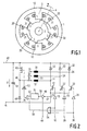
- the reluctance motor according to FIG. 1 comprises a stator 1 with a rotor 2 which can be rotated therein about its longitudinal central axis along a movement coordinate w.
- the stator 1 is provided with three windings 10, 20, 30, which are equally spaced along the movement coordinate w over the circumference of the Stator 1 are distributed.
- Each of the windings 10, 20, 30 is divided into two parts which are applied to two pole shoes 11, 21 and 31 arranged opposite one another.
- the windings 10, 20, 30 form a first cyclic array along the motion coordinate W, where a complete cycle of the stator from stator 1 and the windings 10, 20, 30 a complete revolution that is, an angular range of 360 o along the motion coordinate corresponds w.
- the rotor 2 is provided with four poles or webs 3 which are equally spaced along the movement coordinate w.
- a complete cycle is formed by an angular range of 360 o along the movement coordinate w.
- 2 current pulses are fed into the windings 10, 20, 30 in a cycle corresponding to their arrangement in the stator 1 as a function of the position and the speed of movement of the rotor.
- the length of these current pulses is measured according to the movement coordinate w.
- the first winding 10 is supplied with current in the reproduced position of the rotor 2.
- the forces exerted on the rotor thereby rotate it along the movement coordinate w to a position in which the dashed line 4 drawn radially outward from the center of the rotor 2 is aligned with the dashed line 5 shown in the upper pole piece 11.
- the current pulse in the first winding 10 is ended and at the same time a current pulse is triggered in the second winding 20.
- the forces acting on the rotor 2 thereby turn it further in the direction of the movement coordinate w by 30 o until the pole pieces 21 are opposite two webs 3.
- the current pulse in the second winding 20 is then terminated and a current pulse is accordingly triggered in the third winding 30, by means of which the rotor 2 is rotated a further 30 ° along the movement coordinate w.
- the feeding of the current pulses into the windings 10, 20 and 30 continues until the rotor 2 has made a complete revolution.
- the current pulses occur in a cyclical sequence, whereby a Complete cycle of the current pulses in the exemplary motor according to FIG. 1 corresponds to a complete revolution of the rotor 2.
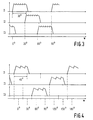
- a sequence of current pulses through the windings 10, 20, 30 is shown in simplified form in FIG. 3.
- I1, I2 and I3 denote the currents in the first, second and third windings 10, 20 and 30, respectively.
- the current pulses I1, I2 and I3 follow each other with a length of 30 o with respect to the movement coordinate w.
- the next current pulse I1 in the first winding 10 follows the end position of the current pulse I3 in the third winding 30, etc.
- the cyclic sequence of the current pulses I1, I2, I3 in the windings 10, 20, 30 shown in FIG. 3 is used at low movement speeds and is shown for such in FIG. 3.
- the speed of movement of the rotor 2 is increased, the length of the current pulses I1, I2, I3 along the movement coordinate w remains unchanged, but the duration of the individual current pulses is reduced. Since the edges of the current pulses I1, I2, I3 are dependent on the inductances of the reluctance motor and thus have at least almost independent time constants on the speed of movement of the rotor 2, the proportion of the edges in the total current pulse increases towards higher movement speeds.
- At movement speeds above a predeterminable value which can be selected on the basis of the structural conditions of the reluctance motor, at least the current pulse which follows in the cyclical sequence for low movement speeds is omitted after each current pulse fed in. Every second pulse is preferably omitted from the cyclical order of the current pulses to be fed in at a low movement speed. This case is shown in Fig. 4. Thereafter, in the cyclical sequence of the current pulses I1, I2, I3 from FIG. 3, every second pulse is omitted, so that the first current pulse I1 shown follows as the next current pulse in the third winding 30 - I3 -. After this current pulse I3 fed in, the current pulse I1 which follows in the cyclical sequence from FIG. 3 is omitted and only the subsequent current pulse I2 is fed in again, etc.
- FIG. 2 shows a particularly simple circuit arrangement for feeding the reluctance motor according to FIG. 1 from a DC voltage source which is connected to two supply voltage connections 40, 41 of the circuit and outputs a DC voltage U which is present at a smoothing capacitor 42 connected to the supply voltage connections 40, 41 .
- asymmetrical H-circuit for each winding 10, 20, 30 of the reluctance motor with a first series branch common to all H-circuits, comprising a series circuit of a current control transistor 43 and a non-return diode 44 which is polarized in the reverse direction with respect to the direct voltage U.
- each asymmetrical H circuit has a second series branch, each of which consists of a selection transistor 12, 22 or 32, a second check diode 13, 23 or 33, which is connected in series therewith and is reverse-polarized with respect to the DC voltage U, and in the example Fig. 2 also consists of a common to all second longitudinal branches measuring element 45.
- the current control transistor 43 and the selection transistors 12, 22 and 32 form the switching elements of the associated series branches, the check diodes 44 and 13, 23, 33 the associated rectifier elements.
- the associated winding 10, 20 or 30 of the reluctance motor is in the transverse branch of the H circuit between the connection points of the switching elements 43; 12, 22 and 32 and the rectifier elements 44; 13, 23 and 33 of each longitudinal branch arranged. These connection points are identified by the reference numerals 46; 14, 24 and 34 marked.
- the common measuring element 45 via which the second longitudinal branches 12, 13; 22, 23 and 32, 33 are led to the terminal 41 of the DC voltage source, is designed as a current measuring element for measuring the amplitudes of the current pulses I1, I2 and I3.
- the current measured value is fed from the measuring element 45 via a measuring line 47 to a subtractor 48 and subtracted therein from a current setpoint value supplied via a current setpoint connection 49.
- the difference formed in this way passes through an input 50 to a current controller 51, which outputs a switching signal for the current control transistor 43 at its output 52.
- This switching signal which can be additionally amplified in an amplifier stage 53, switches the current control transistor 43 on and off at a high frequency, the pulse duty factor being set by the current controller 51 in accordance with the control deviation between the current measured value and the current setpoint.
- the circuit according to FIG. 2 further comprises for each of the selection transistors 12, 22 and 32 a driver amplifier 15, 25 and 35 connected to the base connection thereof, via which the selection transistors 12, 22 and 32 switch signals from selection connections 16, 26 and 36 be forwarded. These switching signals are used to select a winding 10, 20 or 30 to be supplied with a current in the position just assumed for the rotor 2 along its movement coordinate w, so that it is determined in accordance with the control of the Current control transistor 43 which can form current pulses I1, I2 or I3.
- An OR gate 54 also forms a release signal from the three switching signals from the selection connections 16, 26, 36 on a line 55, which, via an AND gate 56, the switching signal for the current control transistor 43 at the output 52 of the current regulator 51 only in the It is permitted to forward time intervals in which at least one of the selection transistors 12, 22 or 32 is conductive and in which a current pulse I1, I2 or I3 is to flow.
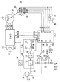
- FIG. 5 shows an exemplary embodiment of a circuit arrangement in block diagram form, with which the reluctance motor according to FIG. 1 can be operated in the described manner according to the invention.
- the motor with stator 1, rotor 2 and windings 10, 20, 30 and the converter arrangement according to FIG. 2 are indicated in the upper part of FIG. 5; the connections of the circuit from FIG. 2 to the direct voltage source 57 as well as the other connections and connection points are provided with the reference symbols already introduced.
- the rotor 2 of the reluctance motor is coupled via a mechanical connection, schematically indicated as a shaft 58, to a position transmitter 59 for delivering a position signal representing the position of the rotor 2 along the movement coordinate w.
- This position transmitter 59 has a movement coordinate transmitter element 60, which moves synchronously with the rotor 2 in the example according to FIG. 5. The exact arrangement of the movement coordinate element 60 can be seen from FIG. 6. Thereafter, the movement coordinate transmitter element 60 is segmented in accordance with the second cyclical arrangement in which the rotor 2 of the reluctance motor is divided.
- the motion coordinate element For this purpose, four sensor elements 60 are arranged, the number of which corresponds to the second cyclical arrangement in the sense that it corresponds to the number of subdivisions of the rotor 2 and thus the segmentation of the movement coordinate element 60.
- the number of sensor elements 61 to 64 corresponds to that of the poles or webs 3 of the rotor 2.
- the sensor elements 61 to 64 are spaced apart from one another by a unit length along the movement coordinate w of the rotor 2, which is one by the smallest common multiple of first cyclic arrangement (of the stator 1) and the second cyclic arrangement (of the rotor 2) forms part of a complete cycle of the stator arrangement.
- the first cyclic arrangement of the stator 1 consists of a sixfold division of the angular range of 360 o corresponding to the pole pieces 11, 21, 31, while the second cyclical arrangement of the rotor 2 has a fourfold division corresponding to the four webs 3 along the circumference of the rotor 2.
- Said length unit then covers a range of 15 o along the movement coordinate w, which corresponds to a twenty-fourth part of the entire circumference of the stator 1 and thus the complete cycle of the stator arrangement.
- the movement coordinate transmitter element 60 is configured cyclically in such a way that each of the sensor elements spaced apart from one another by a length unit along the movement coordinate w over a first section 65, 66, 67 and 68 of two length units each - in present example 30 o - for emitting a first signal value and via a subsequent second section 69, 70, 71 or 72 each of four length units - in the present example 60 o - prompted the delivery of a second.
- the sensor elements 61 to 64 emit signals which are denoted by S1 to S4.
- the position of the sensor elements 61 to 64 relative to the movement coordinate transmitter element 60 is indicated in FIG. 6 by the arrows marked with the names of the signals S1 to S4.
- the different graphic representation of the first sections 65 to 68 from the second sections 69 to 72 indicates the different design of these sections on the movement coordinate element 60.
- Each of the segments preferably has a first region extending over the first section with a first optical and / or electrical and / or magnetic Property and an adjoining, extending over the second section with a second optical and / or electrical and / or magnetic property.
- the sensor elements 61 to 64 are then designed accordingly as optical and / or electrical and / or magnetic sensors.
- the signals S1 to S4 emitted by the sensor elements 61 to 64 which can each take on the two signal values mentioned, together form the position signal.
- This is fed to inputs 73, 74, 75 and 76 of a control unit 77, at which the signals S1 to S4 are referred to as input signals E1 to E4.
- Another input signal E5 of the control unit 77 which is fed to this at an input 78, is made from the signal S1 and the inverted form of the signal S2 by a combination in an AND gate 79 with subsequent Period length doubling is obtained in a flip-flop 80, which is switched over by each falling edge of the signal emitted by the AND gate 79.
- the control unit preferably comprises a memory arrangement, in particular a programmable read-only memory (PROM-EPROM or the like), in which for each value of the position signal and the further input signal at input 78, i.e. for each combination of signal values of the signals E1 to E5, switching information for the windings 10, 20, 30 of the reluctance motor are stored.
- PROM-EPROM programmable read-only memory
- These signals, designated as Q1, Q2 and Q3 are emitted at outputs 81, 82 and 83 of the control unit 77 and fed to the selection connections 16, 26 and 36 of the circuit arrangement shown in FIG. 2.
- the control unit 77 also contains an output 84 for an output signal Q4, which is stored in the control unit 77 in the same way as the switching information Q1, Q2, Q3 and which, when the rotor 2 travels along the movement coordinate w, in each case by one unit of length in its value changes from a first to a second signal value or vice versa.
- a uniform square-wave signal is thus generated, from which an analog speed signal representing the speed of movement of the rotor 2 is obtained in a signal shaping stage 85.
- the signal Q4 is fed directly to a first input 86 of an exclusive-OR gate 87 and to a second input 88 of the gate 87 via an RC low-pass filter 89.
- a pulse sequence of half the period of the signal Q4 arises, which controls a monostable multivibrator 91 with the falling edges of its pulses.
- the signal emitted by the monostable multivibrator 91 consists of Pulses of constant duration and distances dependent on the speed of movement of the rotor 2, ie it has a duty cycle dependent on the speed of movement.
- the DC voltage component is extracted therefrom in a downstream low-pass filter 92 and provided at an output 93 of the waveform stage 85.
- the speed signal from the output 93 is fed to a subtraction stage 94, where it is subtracted as an actual value from a speed setpoint supplied via a setpoint input 95. From the output 96 of the subtraction stage 94, the difference between the speed setpoint and the speed signal (actual value) corresponding to the speed control deviation passes via a PI controller 97 as a current setpoint to the current setpoint connection 49, whereby the loop forming a control arrangement for regulating the speed of movement is closed.
- the speed signal from the output 93 is also fed to two threshold switches 98 and 99 - preferably comparators or Schmitt triggers - which are also acted upon by a reference voltage divider 100 via their taps 101, 102 with reference voltages for representing switching thresholds.
- the first threshold switch 98 delivers a first speed signal via its output 103 at speeds above a first switching threshold, which is designated E7 and is fed to the control unit 77 at an input 105
- the second threshold switch 99 outputs a second speed signal at its output 104 if the speed signal from output 93 of waveform stage 85 exceeds a second switching threshold that is higher than the first Switching threshold.
- This second speed signal is fed as signal E8 to an input 106 of the control unit 77.
- a direction signal E6 is also formed by a direction switch 107 and fed to an associated input 108 of the control unit 77.
- the control unit 77 in the example according to FIG. 5 is entered when certain values of the movement speed of the rotor 2 are exceeded.
- Various measures can be triggered in the control unit 77 by the signals E7, E8 in order to influence the current feed into the windings 10, 20, 30 in different speed ranges.
- more or fewer threshold switches can also be provided for this purpose.
- the signal E7 can preferably be used to shift the position of the rotor 2 and the start and end positions of the current pulses I1, I2, I3 by a certain amount, for example 15 ° .
- the current pulses can then be faded out in the manner described and at the same time the extension and displacement of the current pulses along the movement coordinate w can also be carried out for high speeds.
- the switching information Q1 to Q4 required for the different combinations of the input signals E1 to E8 are stored in the memory arrangement in the control unit 77.
- the position signal is shown in FIG. 7 signals S1 to S4 from the sensor elements, which correspond to the input signals E1 to E4 of the control unit 77, are shown above the movement coordinate W for a complete revolution of the rotor 2, that is to say a complete passage of a cycle along the movement coordinate w.
- the output signal of the AND gate 79 and the further input signal E5 are shown below this.
- the positions of the rotor 2 along the movement coordinate marked with arrows in this diagram are distinguished by the fact that with exact positioning of the sensor elements 61 to 64 and exact formation of the sections 65 to 72 on the movement coordinate transmitter element 60 two flanks of the signals S1 to S4 coincide locally .
- transition states are taken into account in an advantageous embodiment of the control unit 77 contained in the circuit arrangement according to the invention by assigning them defined values for the signals Q1 to Q4 in the memory arrangement, in particular the values of these signals for those along the movement coordinate w correspond to adjacent values of the position signals.
- Table 1 An example of the storage of switching information for switching the windings 10, 20, 30 in the memory arrangement for various position signals including the transition states and various operating cases is shown in part in Table 1 attached to the description.
- the signals S1 to S4 of the sensor elements 61 to 64 are listed in columns on the left as a list of all possible combinations of the position signal, all position signals for a first signal value zero of the further input signal E5 being shown in the first table block A and in block B the same values of the position signal for the case are that the further input signals E5 assumes the second signal value 1.
- blocks C and D are separated by the values of the signal E5 and the possible values of the position signal for the transition states with corresponding tolerances.
- the first operating case labeled 1. corresponds to the movement of the rotor 2 in a first direction at low movement speeds, as is also plotted in FIG. 3.
- the value denoted by the number 1 for the signals Q1 to Q3 means that in the associated rotor position by the assigned one Winding 10, 20 or 30 should flow a current pulse, while the number zero denotes the currentless state of the associated winding 10, 20 or 30.
- the second operating state shown represents the case of a slow movement in the opposite direction.
- the third operating state represents the case of a rapid movement of the rotor 2 in the same direction as in the first operating state. This corresponds to the courses of the currents in the windings 10, 20 and 30 shown in FIG. 4.
- the speed of movement is regulated by controlling the amplitudes of the current pulses I1 to I3.
- the circuit arrangement according to FIG. 5 contains two coupled control loops, the current setpoint being determined in an outer control loop via the PI controller 97 and made available at the current setpoint connection 49 for the inner control loop shown in FIG. 2 with the current controller 51.
- the current controller 51 controls the current control transistor 43 in the sense of a duty cycle control, which results in the sawtooth-shaped current profiles in the current pulses I1 to I3 in FIGS. 3 and 4.
- the arrangement described above can also be used with little modification, for example for linear motors, in addition to rotating motors.
- a linear motor the rotationally symmetrical arrangements of rotor and stator from FIG. 1 are replaced by linear arrangements which correspond in their construction to a development of the reluctance motor shown, the distribution of the stator and Rotor arrangement results in a configuration that forms a complete cycle for the linear motor corresponding to the complete stator arrangement.
- Such cycles can be arranged several times in a row in the linear motor.
- the motion coordinate w is then determined in the Cartesian coordinate system.
- the circuit arrangement shown in FIG. 5 essentially forms an analog control; the function of the controller, the waveform stage for the speed signal and the threshold switch can, however, also be combined to form a digital control.
Landscapes
- Engineering & Computer Science (AREA)
- Power Engineering (AREA)
- Control Of Electric Motors In General (AREA)
- Control Of Motors That Do Not Use Commutators (AREA)
Applications Claiming Priority (2)
| Application Number | Priority Date | Filing Date | Title |
|---|---|---|---|
| DE4029335 | 1990-09-15 | ||
| DE4029335A DE4029335A1 (de) | 1990-09-15 | 1990-09-15 | Schaltungsanordnung zum kommutieren eines reluktanzmotors |
Publications (2)
| Publication Number | Publication Date |
|---|---|
| EP0476751A2 true EP0476751A2 (fr) | 1992-03-25 |
| EP0476751A3 EP0476751A3 (en) | 1993-05-26 |
Family
ID=6414340
Family Applications (1)
| Application Number | Title | Priority Date | Filing Date |
|---|---|---|---|
| EP19910202302 Withdrawn EP0476751A3 (en) | 1990-09-15 | 1991-09-10 | Commutating circuit for a reluctance motor |
Country Status (4)
| Country | Link |
|---|---|
| US (1) | US5350990A (fr) |
| EP (1) | EP0476751A3 (fr) |
| JP (1) | JPH04255492A (fr) |
| DE (1) | DE4029335A1 (fr) |
Cited By (2)
| Publication number | Priority date | Publication date | Assignee | Title |
|---|---|---|---|---|
| DE4239668C1 (de) * | 1992-11-26 | 1994-03-31 | Daimler Benz Ag | Verfahren zum Ansteuern eines Reluktanzmotors |
| EP2106019A1 (fr) * | 2008-03-26 | 2009-09-30 | Panasonic Electric Works Co., Ltd. | Procédé de contrôle de fonctionnement d'un moteur à vibration linéaire |
Families Citing this family (8)
| Publication number | Priority date | Publication date | Assignee | Title |
|---|---|---|---|---|
| IT1259115B (it) * | 1992-06-17 | 1996-03-11 | Askoll Spa | Dispositivo elettronico per l'avviamento di un motore sincrono con rotore a magnete permanente |
| GB9300734D0 (en) * | 1993-01-14 | 1993-03-03 | Switched Reluctance Drives Ltd | High voltage power converters for switched reluctance motors |
| DE19527983A1 (de) * | 1995-07-31 | 1997-02-06 | Aeg Kleinmotoren Gmbh | Steuerung für einen geschalteten Reluktanzmotor |
| US6060858A (en) * | 1998-08-18 | 2000-05-09 | Dana Corporation | C-dump switched reluctance hysteresis control |
| JP2002252953A (ja) * | 2001-02-23 | 2002-09-06 | Alps Electric Co Ltd | インナーロータモータおよびディスク装置 |
| US6744587B2 (en) * | 2001-06-29 | 2004-06-01 | Seagate Technology Llc | Motor control circuit with adaptive controller path selection for different load conditions |
| JP2005354810A (ja) * | 2004-06-10 | 2005-12-22 | Nidec Shibaura Corp | ブラシレスdcモータの駆動装置 |
| DE102004034470A1 (de) | 2004-07-15 | 2006-02-16 | Elektra Gmbh | Steuerung für einen geschalteten Reluktanzmotor |
Family Cites Families (13)
| Publication number | Priority date | Publication date | Assignee | Title |
|---|---|---|---|---|
| US3704462A (en) * | 1970-09-21 | 1972-11-28 | Miniature Elect Components | Manually resettable electromagnetic indicators |
| DE2260069A1 (de) * | 1972-12-08 | 1974-06-12 | Papst Motoren Kg | Kollektroloser gleichstrommotor |
| US4169990A (en) * | 1974-06-24 | 1979-10-02 | General Electric Company | Electronically commutated motor |
| JPS5329787A (en) * | 1976-08-31 | 1978-03-20 | Kagaku Gijutsucho Hoshasen Igaku Sogo Kenkyusho | Measuring device for radiation |
| US4065704A (en) * | 1976-09-10 | 1977-12-27 | General Electric Company | Static speed control circuit for polyphase induction motors |
| GB1591346A (en) * | 1977-03-30 | 1981-06-17 | Chloride Group Ltd | Reluctance electric motor drive systems |
| GB1572586A (en) * | 1978-03-22 | 1980-07-30 | Mfe Corp | Disc drive system |
| CH658348A5 (de) * | 1979-11-30 | 1986-10-31 | Papst Motoren Kg | Zweipulsiger kollektorloser gleichstrommotor. |
| US4479078A (en) * | 1980-06-20 | 1984-10-23 | Kollmorgen Technologies Corporation | Brushless motor controller |
| US4739240A (en) * | 1987-04-29 | 1988-04-19 | General Electric Company | Commutator for switched reluctance drive |
| DE3819097A1 (de) * | 1988-06-04 | 1989-12-14 | Philips Patentverwaltung | Schaltungsanordnung zum speisen eines reluktanzmotors |
| US4942345A (en) * | 1989-02-14 | 1990-07-17 | Emerson Electric Co. | Pole changing switched reluctance motor and method |
| US4933620A (en) * | 1989-05-09 | 1990-06-12 | General Electric Company | Control system for low speed switched reluctance motor |
-
1990
- 1990-09-15 DE DE4029335A patent/DE4029335A1/de not_active Withdrawn
-
1991
- 1991-09-10 EP EP19910202302 patent/EP0476751A3/de not_active Withdrawn
- 1991-09-11 US US07/758,939 patent/US5350990A/en not_active Expired - Fee Related
- 1991-09-13 JP JP3234853A patent/JPH04255492A/ja active Pending
Cited By (4)
| Publication number | Priority date | Publication date | Assignee | Title |
|---|---|---|---|---|
| DE4239668C1 (de) * | 1992-11-26 | 1994-03-31 | Daimler Benz Ag | Verfahren zum Ansteuern eines Reluktanzmotors |
| EP0599334A3 (fr) * | 1992-11-26 | 1995-04-05 | Daimler Benz Ag | Procédé d'entraînement d'un moteur à reluctance. |
| EP2106019A1 (fr) * | 2008-03-26 | 2009-09-30 | Panasonic Electric Works Co., Ltd. | Procédé de contrôle de fonctionnement d'un moteur à vibration linéaire |
| RU2395156C1 (ru) * | 2008-03-26 | 2010-07-20 | Панасоник Электрик Воркс Ко., Лтд. | Способ управления линейным вибрационным двигателем |
Also Published As
| Publication number | Publication date |
|---|---|
| US5350990A (en) | 1994-09-27 |
| DE4029335A1 (de) | 1992-03-19 |
| EP0476751A3 (en) | 1993-05-26 |
| JPH04255492A (ja) | 1992-09-10 |
Similar Documents
| Publication | Publication Date | Title |
|---|---|---|
| DE3813130C2 (de) | Digitale Steuereinheit für einen geschalteten Reluktanzmotor | |
| DE3781542T2 (de) | Steuergeraet und methode zur steurerung eines schrittschaltreluktanzmotors. | |
| DE2225442C3 (de) | Kollektorloser Gleichstrommotor | |
| DE3200664C2 (de) | Kommutatorloser Elektromotor | |
| DE3122828C2 (de) | Steuerschaltung zum Stoppen bürstenloser Gleichstrommotoren | |
| DE1538834C3 (de) | Schrittmotor | |
| EP3874592B1 (fr) | Procédé et agencement de commutation pour la détection de charge sans capteur pour des moteurs pas-à-pas | |
| DE3819062C3 (de) | Verfahren zur Steuerung von bürstenlosen Elektromotoren sowie Steuerschaltung hierfür | |
| DE2556952A1 (de) | Kombiniertes, digitales steuerungs- und regelungssystem fuer einen gleichstrommotor | |
| DE2620935A1 (de) | Motor mit veraenderlichem magnetischen widerstand | |
| EP0476751A2 (fr) | Circuit de commutation pour moteur à reluctance | |
| DE2020793A1 (de) | Gleichstrommotor | |
| EP0470672A2 (fr) | Arrangement d'un circuit de commutation d'un moteur à réluctance | |
| DE3819064C3 (de) | Verfahren zur Steuerung von bürstenlosen Elektromotoren sowie Steuerschaltung hierfür | |
| DE2057073A1 (de) | Antriebssystem mit Reluktanzmotor | |
| DE3913501A1 (de) | Kommutatorloser, magnetisch gesteuerter elektromotor | |
| DE3124080C2 (fr) | ||
| DE69708351T2 (de) | Gerät zur Detektion der externen Induktion für die Kommutierung eines Motors mit veränderlicher Reluktanz | |
| DE69206503T2 (de) | Hochgeschwindigkeits-gleichstrommotor. | |
| DE4036565C1 (en) | Electronic drive system using variable reluctance electric motor - slows down variations in magnetic induction of stator by electronic control of winding current | |
| DE2254123A1 (de) | Anordnung zur stromspeisung eines stufenmotors | |
| DE2547764B2 (de) | Elektronisch kommutierter Gleichstrommotor | |
| WO1998052275A1 (fr) | Moteur a commutation electronique | |
| DE2321022C2 (de) | Kollektorloser Gleichstrommotor mit einem axialen Luftspalt | |
| DE2727471C3 (de) | Elektronisch kommutierter Reluktanzmotor |
Legal Events
| Date | Code | Title | Description |
|---|---|---|---|
| PUAI | Public reference made under article 153(3) epc to a published international application that has entered the european phase |
Free format text: ORIGINAL CODE: 0009012 |
|
| AK | Designated contracting states |
Kind code of ref document: A2 Designated state(s): DE FR GB |
|
| PUAL | Search report despatched |
Free format text: ORIGINAL CODE: 0009013 |
|
| AK | Designated contracting states |
Kind code of ref document: A3 Designated state(s): DE FR GB |
|
| 17P | Request for examination filed |
Effective date: 19931122 |
|
| 17Q | First examination report despatched |
Effective date: 19940721 |
|
| STAA | Information on the status of an ep patent application or granted ep patent |
Free format text: STATUS: THE APPLICATION IS DEEMED TO BE WITHDRAWN |
|
| 18D | Application deemed to be withdrawn |
Effective date: 19960207 |