EP0476240A1 - Anlage zum Spannen von einer Bearbeitungsmaschine zuzuführenden Holzstämmen - Google Patents
Anlage zum Spannen von einer Bearbeitungsmaschine zuzuführenden Holzstämmen Download PDFInfo
- Publication number
- EP0476240A1 EP0476240A1 EP91110415A EP91110415A EP0476240A1 EP 0476240 A1 EP0476240 A1 EP 0476240A1 EP 91110415 A EP91110415 A EP 91110415A EP 91110415 A EP91110415 A EP 91110415A EP 0476240 A1 EP0476240 A1 EP 0476240A1
- Authority
- EP
- European Patent Office
- Prior art keywords
- logs
- track
- transport chain
- carriages
- guide rail
- Prior art date
- Legal status (The legal status is an assumption and is not a legal conclusion. Google has not performed a legal analysis and makes no representation as to the accuracy of the status listed.)
- Withdrawn
Links
- 238000009434 installation Methods 0.000 title claims abstract 5
- 210000000078 claw Anatomy 0.000 claims description 14
- 230000003134 recirculating effect Effects 0.000 claims description 3
- 230000000284 resting effect Effects 0.000 claims description 2
- 230000005484 gravity Effects 0.000 description 2
- 239000000969 carrier Substances 0.000 description 1
- 238000010276 construction Methods 0.000 description 1
- 230000007812 deficiency Effects 0.000 description 1
- 230000000630 rising effect Effects 0.000 description 1
Images


Classifications
-
- B—PERFORMING OPERATIONS; TRANSPORTING
- B27—WORKING OR PRESERVING WOOD OR SIMILAR MATERIAL; NAILING OR STAPLING MACHINES IN GENERAL
- B27B—SAWS FOR WOOD OR SIMILAR MATERIAL; COMPONENTS OR ACCESSORIES THEREFOR
- B27B31/00—Arrangements for conveying, loading, turning, adjusting, or discharging the log or timber, specially designed for saw mills or sawing machines
- B27B31/006—Arrangements for conveying, loading, turning, adjusting, or discharging the log or timber, specially designed for saw mills or sawing machines with chains or belts
-
- B—PERFORMING OPERATIONS; TRANSPORTING
- B23—MACHINE TOOLS; METAL-WORKING NOT OTHERWISE PROVIDED FOR
- B23Q—DETAILS, COMPONENTS, OR ACCESSORIES FOR MACHINE TOOLS, e.g. ARRANGEMENTS FOR COPYING OR CONTROLLING; MACHINE TOOLS IN GENERAL CHARACTERISED BY THE CONSTRUCTION OF PARTICULAR DETAILS OR COMPONENTS; COMBINATIONS OR ASSOCIATIONS OF METAL-WORKING MACHINES, NOT DIRECTED TO A PARTICULAR RESULT
- B23Q7/00—Arrangements for handling work specially combined with or arranged in, or specially adapted for use in connection with, machine tools, e.g. for conveying, loading, positioning, discharging, sorting
- B23Q7/03—Arrangements for handling work specially combined with or arranged in, or specially adapted for use in connection with, machine tools, e.g. for conveying, loading, positioning, discharging, sorting by means of endless chain conveyors
- B23Q7/035—Arrangements for handling work specially combined with or arranged in, or specially adapted for use in connection with, machine tools, e.g. for conveying, loading, positioning, discharging, sorting by means of endless chain conveyors on which work holders are fixed
-
- B—PERFORMING OPERATIONS; TRANSPORTING
- B27—WORKING OR PRESERVING WOOD OR SIMILAR MATERIAL; NAILING OR STAPLING MACHINES IN GENERAL
- B27B—SAWS FOR WOOD OR SIMILAR MATERIAL; COMPONENTS OR ACCESSORIES THEREFOR
- B27B25/00—Feeding devices for timber in saw mills or sawing machines; Feeding devices for trees
- B27B25/04—Feeding devices for timber in saw mills or sawing machines; Feeding devices for trees with feed chains or belts
-
- B—PERFORMING OPERATIONS; TRANSPORTING
- B27—WORKING OR PRESERVING WOOD OR SIMILAR MATERIAL; NAILING OR STAPLING MACHINES IN GENERAL
- B27B—SAWS FOR WOOD OR SIMILAR MATERIAL; COMPONENTS OR ACCESSORIES THEREFOR
- B27B29/00—Gripping, clamping or holding devices for the trunk or log in saw mills or sawing machines; Travelling trunk or log carriages
- B27B29/08—Trunk or log carriages with gripping means designed to pass the saw blade(s), especially for band saws; Arrangement of gripping accessories thereon; Turning devices thereon
Definitions
- the invention relates to a system for tensioning logs to be fed to a processing machine, in particular crooked timber, in which the logs rest in the longitudinal direction on a transport chain and are fixed on it by carriers which rest on the logs from above and are closed on a conveyor arranged above the transport chain
- the track is moved in synchronism with the transport chain and its downward movement on the logs is controlled by a guide rail or the like.
- the drivers are designed as pivotable about transverse axes to the direction of movement horizontal axes, provided at their ends with tips or cutting levers on the links of an endless chain are arranged, which run on a closed path running in a vertical plane.
- the levers swing down and penetrate the logs with their tips or blades in order to fix them on the transport chain so that they do not move as they pass through the sawmill.
- the object of the invention is to avoid these deficiencies and to provide an education which is robust and simple in construction and works trouble-free when logs of very different diameters are fed one after the other on the transport chain or when the logs are crooked.
- the drivers are designed as weighted thrust pieces which are movably arranged in the vertical direction on carriages which run in a hanging manner on the track running in a horizontal plane.
- Plants are also known in which the logs are fixed by resting weights (DE-PS 302 298 and DE-OS 24 42 447). However, these do not move with the logs, but are designed as rollers or provided with rollers under which the logs are moved away. However, especially with Krummholz, there is no guarantee of good management. They are also complicated and expensive. Also, in the case of DE-OS 24 42 447, one does not need a single so-called "feed unit", but several are required in succession if a sufficiently secure clamping is to be achieved.
- the carriages can all be connected to one another by chains or other means to form a closed row and have a common drive. They then all move at the same speed, which corresponds to the speed of the transport chain on which the logs lie. However, it is also possible to drive the carriages individually or in groups separately. It is then possible to run them only on the tract of the track that lies above the transport chain at the speed of the transport chain, while they are driven faster on the rest of the longer part of the track. You can get by with a smaller number of carriages and pressure pieces.
- the guide rail used to control the up and down movement of the pressure pieces is preferably guided alongside the track. Besides that - related to the direction of rotation of the carriages - the beginning of the part of the track that is above the transport chain lowers the guide rail and rises again at the end of this part.
- the pressure pieces are provided with a roller that runs on the guide rail.
- the rising part of the guide rail can also be replaced by a lifting mechanism which raises the lowered thrust pieces back to the level at which they were before lowering, so that the roller provided on the thrust pieces comes back onto the guide rail.
- the thrust pieces are provided with downward-pointing tips or cutting edges which penetrate into the surface of the logs.
- the tips or cutting edges are preferably provided at the two ends of claws extending in the direction of movement, which are pivotally mounted on the pressure pieces in the middle about a horizontal axis running transversely to the direction of movement.
- the adaptability can be further improved in that two such claws are provided on each pressure piece, which are mounted at the ends of a two-armed lever extending in the direction of movement, which in turn is pivotally mounted on the pressure piece about a horizontal axis extending to the direction of movement. This allows gaps between two successive logs to be bridged.
- the pivoting movements of the claws and the two-armed lever are limited in both pivoting directions by stops provided on the pressure pieces or on the lever.
- the pressure pieces must move freely up and down in the carriage.
- they are tapered like wedges at the front and rear, in relation to the direction of movement of the carriages, and each is provided with a vertically arranged guide rod.
- the thrust pieces are stored in recirculating ball bushings or other elements similar to ball bearings, which are arranged in the carriage.
- FIGS. 1 and 2 The system shown in FIGS. 1 and 2 has a horizontally running transport chain 1, on which logs 2 are guided through a sawmill 3, for example a double-shaft saw, shown schematically in broken lines.
- a closed track 4 lying in a horizontal plane, from which the section shown in FIG. 1 below runs vertically above the transport chain 1.
- weighted pressure pieces 8 are guided freely movable in the vertical direction. They are each provided with a lateral roller 9 which overlaps a guide rail 10 which is guided along the track 4.
- Fig. 1 the course of the transport chain 1 and the track 4 is shown side by side for reasons of clarity.
- career 4 be arranged directly vertically above the conveyor chain 1 in the part passing through the sawmill 3.
- the pressure pieces 8 are provided with claws 11 which have downward-pointing tips or cutting edges 12 which penetrate into the surface of the logs 2 when the pressure pieces are lowered.
- the guide rail 10 is lowered in the region of the tract of the track 4 lying above the transport chain 1, so that the pressure pieces 8 carried in a raised position by the rollers 9 in the remaining regions of the guide rail 8 are under the action of gravity and, if appropriate, additionally Move springs 13 downwards in this area until they rest on the logs 2. You press them firmly onto the transport chain 1 so that the logs cannot move on it when they are passed through the sawmill 3.
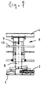
- each carriage 6 consists of a frame 14 which hangs on the track 4 by means of the rollers 5 and in which the pressure piece 8 can be moved up and down.
- four guide blocks 15 are provided in the frame 14, which are provided with recirculating ball bushings 17 and in which the pressure piece 8 is smoothly guided with hardened and ground perpendicular round rods 16 attached at the front and rear (FIG. 5).
- a claw 11 is pivotally arranged about a bolt 20 in a groove 18 running in the direction of movement (FIG. 3, carriage on the right in the picture), or as shown on the carriage on the left in the picture and in FIG. 2
- Two-armed levers 19 are provided, on the two ends of which a claw 11 is pivotably arranged in a groove 21 about bolts 22 in the same way. In all cases, the bottom of the grooves 18 u.
- rollers 5 of the carriages 6 run within two U-shaped rails that form the track 4.
- the career can also have a different profile.
- the carriages 6 have rollers 25 on both sides for guidance along the guide rails 23.
- additional rollers 26 are provided on the carriages at the top, which cause the carriages to be guided within the raceway 4.
Landscapes
- Life Sciences & Earth Sciences (AREA)
- Engineering & Computer Science (AREA)
- Mechanical Engineering (AREA)
- Wood Science & Technology (AREA)
- Forests & Forestry (AREA)
- Framework For Endless Conveyors (AREA)
Applications Claiming Priority (2)
| Application Number | Priority Date | Filing Date | Title |
|---|---|---|---|
| DE19904026088 DE4026088C1 (enExample) | 1990-08-17 | 1990-08-17 | |
| DE4026088 | 1990-08-17 |
Publications (1)
| Publication Number | Publication Date |
|---|---|
| EP0476240A1 true EP0476240A1 (de) | 1992-03-25 |
Family
ID=6412433
Family Applications (1)
| Application Number | Title | Priority Date | Filing Date |
|---|---|---|---|
| EP91110415A Withdrawn EP0476240A1 (de) | 1990-08-17 | 1991-06-24 | Anlage zum Spannen von einer Bearbeitungsmaschine zuzuführenden Holzstämmen |
Country Status (2)
| Country | Link |
|---|---|
| EP (1) | EP0476240A1 (enExample) |
| DE (1) | DE4026088C1 (enExample) |
Families Citing this family (2)
| Publication number | Priority date | Publication date | Assignee | Title |
|---|---|---|---|---|
| EP1674221B1 (en) * | 2004-12-22 | 2013-10-09 | Renholmens Mekaniska Ab | Device for crosscutting lengths of wood |
| ITPD20130104A1 (it) * | 2013-04-22 | 2014-10-23 | Trc Srl | Carrello per trasportatori/manovie |
Citations (6)
| Publication number | Priority date | Publication date | Assignee | Title |
|---|---|---|---|---|
| US2387446A (en) * | 1943-07-31 | 1945-10-23 | Irwin Machinery Company | Board feed for woodworking machines |
| US2581682A (en) * | 1949-07-07 | 1952-01-08 | Elmer L Mccormick | Wedge sawing machine |
| DE1652387A1 (de) * | 1966-02-24 | 1971-09-16 | Zuckermann Kg Maschf | Kopiermaschine zum Laengsbearbeiten von Werkstuecken aus Holz u.dgl. |
| FR2128182A1 (enExample) * | 1971-03-10 | 1972-10-20 | Guilliet Ets | |
| FR2201953A1 (enExample) * | 1972-10-05 | 1974-05-03 | Aresca Angelo | |
| DE3800228C1 (en) * | 1988-01-07 | 1989-07-13 | Central'nyj Naucno-Issledovatel'skij I Proektno-Eksperimental'nyj Institut Organizacii, Mechanizacii I Techniceskoj Pomosci Stroitel'stvu, Moskau/Moskva, Su | Longitudinal-advancing device for rod material |
Family Cites Families (2)
| Publication number | Priority date | Publication date | Assignee | Title |
|---|---|---|---|---|
| DE960383C (de) * | 1953-12-05 | 1957-03-21 | Paul Fries | Aus zwei uebereinanderliegenden Foerderketten bestehende Vorschubeinrichtung fuer Kreissaegen, Bandsaegen und aehnliche Maschinen |
| DE1503926A1 (de) * | 1965-07-28 | 1969-07-17 | Eriksson Ab Ak | Vorrichtung zum Zufuehren von Staemmen in Holzsaegen |
-
1990
- 1990-08-17 DE DE19904026088 patent/DE4026088C1/de not_active Expired - Fee Related
-
1991
- 1991-06-24 EP EP91110415A patent/EP0476240A1/de not_active Withdrawn
Patent Citations (6)
| Publication number | Priority date | Publication date | Assignee | Title |
|---|---|---|---|---|
| US2387446A (en) * | 1943-07-31 | 1945-10-23 | Irwin Machinery Company | Board feed for woodworking machines |
| US2581682A (en) * | 1949-07-07 | 1952-01-08 | Elmer L Mccormick | Wedge sawing machine |
| DE1652387A1 (de) * | 1966-02-24 | 1971-09-16 | Zuckermann Kg Maschf | Kopiermaschine zum Laengsbearbeiten von Werkstuecken aus Holz u.dgl. |
| FR2128182A1 (enExample) * | 1971-03-10 | 1972-10-20 | Guilliet Ets | |
| FR2201953A1 (enExample) * | 1972-10-05 | 1974-05-03 | Aresca Angelo | |
| DE3800228C1 (en) * | 1988-01-07 | 1989-07-13 | Central'nyj Naucno-Issledovatel'skij I Proektno-Eksperimental'nyj Institut Organizacii, Mechanizacii I Techniceskoj Pomosci Stroitel'stvu, Moskau/Moskva, Su | Longitudinal-advancing device for rod material |
Non-Patent Citations (1)
| Title |
|---|
| PATENT ABSTRACTS OF JAPAN, Vol. 9, No. 92 (M-373)[1815] 20 April 1985; & JP-A-59 217 511 (ISEKI NOKI K.K.) 7 Dezember 1984, Zusammenfassung. * |
Also Published As
| Publication number | Publication date |
|---|---|
| DE4026088C1 (enExample) | 1991-06-20 |
Similar Documents
| Publication | Publication Date | Title |
|---|---|---|
| DE2825213C2 (de) | Vorrichtung zum Überführen von Gegenständen aus einer Förderbahn in eine Arbeitsstation | |
| DE3621357C1 (de) | Kappsaege zum Ablaengen von Brettern | |
| DE2714973C2 (de) | Vorrichtung zum Vorschieben von Rohbrettern zu einer Kantenbesäumsäge | |
| DE3142378A1 (de) | "maschine zur selbsttaetigen montage von reifen auf felgen" | |
| DE2754502A1 (de) | Vorrichtung zum axialen transportieren von holzstuecken durch eine bearbeitungsstation | |
| DE3448040C2 (enExample) | ||
| EP0476240A1 (de) | Anlage zum Spannen von einer Bearbeitungsmaschine zuzuführenden Holzstämmen | |
| DE2600663A1 (de) | Anlage fuer von den lagerbetten eines lagers zu einer schere oder dergleichen zu foerdernde betonstahlstaebe | |
| DE9313029U1 (de) | Sortiermaschine mit Fördereinrichtungen | |
| DE2320730A1 (de) | Vorrichtung zum stapeln besaeumter und unbesaeumter bretter | |
| EP0234333B1 (de) | Fördereinrichtung für Baumstämme | |
| DE2618568A1 (de) | Zufuehr-vorrichtung fuer materialstaebe | |
| DE3031916C2 (de) | Fördereinrichtung mit geneigter Rollfläche für Rundmaterial | |
| DE112009000720B4 (de) | Fördervorrichtung für eine Anlage zur Keilverzinkung von Holzstücken | |
| DE1183428B (de) | Einrichtung zum Zufuehren von auf einem Foerderband bewegten und in Gruppen aufgeteilten Gegenstaenden, beispielsweise Flaschen u. dgl., zu kontinuierlich bewegten Greifern | |
| DE3218464C2 (enExample) | ||
| DE19805574B4 (de) | Verfahren und Vorrichtung zum Transport und zur Vorbereitung von hohlen Profilstäben aus Kunststoff für die Bildung von Fensterrahmen | |
| EP0499797A1 (de) | Ausrichtvorrichtung für zu bearbeitende Hölzer | |
| DE2952764C2 (de) | Durchlauflager für stabförmige Gegenstände | |
| DE2064178B2 (de) | Querfoerderanlage fuer baumstaemme | |
| DE2309820A1 (de) | Hobel | |
| WO1987006564A1 (fr) | Convoyeur pour le transport de pieces | |
| DE1740375U (de) | Foerderbandanlage. | |
| DE3403959A1 (de) | Wehr mit dammbalkenfuehrungen und hebe- und absenkvorrichtung | |
| DE3228224C2 (de) | Vorrichtung zum Zuführen von Holz |
Legal Events
| Date | Code | Title | Description |
|---|---|---|---|
| PUAI | Public reference made under article 153(3) epc to a published international application that has entered the european phase |
Free format text: ORIGINAL CODE: 0009012 |
|
| AK | Designated contracting states |
Kind code of ref document: A1 Designated state(s): AT DE FR IT NL SE |
|
| 17P | Request for examination filed |
Effective date: 19920817 |
|
| RAP1 | Party data changed (applicant data changed or rights of an application transferred) |
Owner name: SALZGITTER MASCHINENBAU GMBH |
|
| RAP1 | Party data changed (applicant data changed or rights of an application transferred) |
Owner name: SALZGITTER MASCHINENBAU GMBH |
|
| 17Q | First examination report despatched |
Effective date: 19940201 |
|
| STAA | Information on the status of an ep patent application or granted ep patent |
Free format text: STATUS: THE APPLICATION IS DEEMED TO BE WITHDRAWN |
|
| 18D | Application deemed to be withdrawn |
Effective date: 19940628 |