EP0475467B1 - Wirbelkammerabscheider - Google Patents
Wirbelkammerabscheider Download PDFInfo
- Publication number
- EP0475467B1 EP0475467B1 EP91120013A EP91120013A EP0475467B1 EP 0475467 B1 EP0475467 B1 EP 0475467B1 EP 91120013 A EP91120013 A EP 91120013A EP 91120013 A EP91120013 A EP 91120013A EP 0475467 B1 EP0475467 B1 EP 0475467B1
- Authority
- EP
- European Patent Office
- Prior art keywords
- flow
- swirl chamber
- separator
- swirl
- chamber separator
- Prior art date
- Legal status (The legal status is an assumption and is not a legal conclusion. Google has not performed a legal analysis and makes no representation as to the accuracy of the status listed.)
- Expired - Lifetime
Links
Images


Classifications
-
- B—PERFORMING OPERATIONS; TRANSPORTING
- B01—PHYSICAL OR CHEMICAL PROCESSES OR APPARATUS IN GENERAL
- B01D—SEPARATION
- B01D17/00—Separation of liquids, not provided for elsewhere, e.g. by thermal diffusion
- B01D17/02—Separation of non-miscible liquids
- B01D17/0217—Separation of non-miscible liquids by centrifugal force
-
- B—PERFORMING OPERATIONS; TRANSPORTING
- B01—PHYSICAL OR CHEMICAL PROCESSES OR APPARATUS IN GENERAL
- B01D—SEPARATION
- B01D21/00—Separation of suspended solid particles from liquids by sedimentation
- B01D21/0087—Settling tanks provided with means for ensuring a special flow pattern, e.g. even inflow or outflow
-
- B—PERFORMING OPERATIONS; TRANSPORTING
- B01—PHYSICAL OR CHEMICAL PROCESSES OR APPARATUS IN GENERAL
- B01D—SEPARATION
- B01D21/00—Separation of suspended solid particles from liquids by sedimentation
- B01D21/26—Separation of sediment aided by centrifugal force or centripetal force
- B01D21/265—Separation of sediment aided by centrifugal force or centripetal force by using a vortex inducer or vortex guide, e.g. coil
-
- B—PERFORMING OPERATIONS; TRANSPORTING
- B01—PHYSICAL OR CHEMICAL PROCESSES OR APPARATUS IN GENERAL
- B01D—SEPARATION
- B01D45/00—Separating dispersed particles from gases or vapours by gravity, inertia, or centrifugal forces
- B01D45/12—Separating dispersed particles from gases or vapours by gravity, inertia, or centrifugal forces by centrifugal forces
- B01D45/16—Separating dispersed particles from gases or vapours by gravity, inertia, or centrifugal forces by centrifugal forces generated by the winding course of the gas stream, the centrifugal forces being generated solely or partly by mechanical means, e.g. fixed swirl vanes
-
- B—PERFORMING OPERATIONS; TRANSPORTING
- B04—CENTRIFUGAL APPARATUS OR MACHINES FOR CARRYING-OUT PHYSICAL OR CHEMICAL PROCESSES
- B04C—APPARATUS USING FREE VORTEX FLOW, e.g. CYCLONES
- B04C3/00—Apparatus in which the axial direction of the vortex flow following a screw-thread type line remains unchanged ; Devices in which one of the two discharge ducts returns centrally through the vortex chamber, a reverse-flow vortex being prevented by bulkheads in the central discharge duct
- B04C3/06—Construction of inlets or outlets to the vortex chamber
-
- B—PERFORMING OPERATIONS; TRANSPORTING
- B04—CENTRIFUGAL APPARATUS OR MACHINES FOR CARRYING-OUT PHYSICAL OR CHEMICAL PROCESSES
- B04C—APPARATUS USING FREE VORTEX FLOW, e.g. CYCLONES
- B04C5/00—Apparatus in which the axial direction of the vortex is reversed
- B04C5/12—Construction of the overflow ducting, e.g. diffusing or spiral exits
- B04C5/13—Construction of the overflow ducting, e.g. diffusing or spiral exits formed as a vortex finder and extending into the vortex chamber; Discharge from vortex finder otherwise than at the top of the cyclone; Devices for controlling the overflow
-
- B—PERFORMING OPERATIONS; TRANSPORTING
- B04—CENTRIFUGAL APPARATUS OR MACHINES FOR CARRYING-OUT PHYSICAL OR CHEMICAL PROCESSES
- B04C—APPARATUS USING FREE VORTEX FLOW, e.g. CYCLONES
- B04C5/00—Apparatus in which the axial direction of the vortex is reversed
- B04C5/24—Multiple arrangement thereof
-
- B—PERFORMING OPERATIONS; TRANSPORTING
- B04—CENTRIFUGAL APPARATUS OR MACHINES FOR CARRYING-OUT PHYSICAL OR CHEMICAL PROCESSES
- B04C—APPARATUS USING FREE VORTEX FLOW, e.g. CYCLONES
- B04C7/00—Apparatus not provided for in group B04C1/00, B04C3/00, or B04C5/00; Multiple arrangements not provided for in one of the groups B04C1/00, B04C3/00, or B04C5/00; Combinations of apparatus covered by two or more of the groups B04C1/00, B04C3/00, or B04C5/00
Definitions
- the invention relates to a vortex chamber separator for separating and / or separating solid and / or liquid particles (disperse phase) from gaseous and / or liquid media (continuous phase) and for separating mixed gases (gas-gas separation) and / or mixed Liquids (liquid-liquid separation) as well as for sifting and / or classifying, with at least one vortex chamber with a sharp trailing edge at the entrance of the main flow channel into the vortex chamber and two immersion tubes, which are arranged coaxially to one another and parallel to the trailing edge in the vortex chamber each stretch first from their end walls and are connected to a clean gas outlet and have a widening outlet, in the swirl chamber separator, in which a centrifugal force field is generated, from which the specifically lighter portion by two projecting coaxially and in mirror image to the middle planes of the swirl chamber separator Diving ear is sucked off within the central area of the swirl chamber separator.
- the vortex separation process as a fluid mechanical separation process in which centrifugal forces are used to separate or separate a heavy disperse phase from a lighter, continuous, flowable carrier phase from aerobic and / or hydrodispersions is known per se.
- DE-A-32 03 498 e.g. a generic swirl chamber separator described.
- this has the disadvantage that, due to flow losses in the swirl chamber separator, its separating capacity is relatively low in relation to the energy input and the multi-chamber arrangements which are often required to increase the separating capacity have a relatively large construction volume. This limits the area of use of the known swirl chamber separators.
- the bottom layer flow is formed rotationally symmetrically at a constant or approximately constant mean main flow velocity and the wall layer flow of the vortex in the vortex chamber and the main flow in the main flow channel and the trailing edge are supplied so concavely curved that the vertical secondary velocities on both sides of the trailing edge are directed in the same direction and are of the same local size.
- the clean gas flow is led through the immersion tubes in such a way that the flow is only loaded with weak meridian flow deflections in zones of maximum flow velocity.
- the object of the invention is to design a swirl chamber separator of the type mentioned at the outset in such a way that a structural simplification is achieved if the reduction in the immersion tube losses is not fully optimized.
- the contact zone between the main flow and the vortex is also set to the fixed cylinder jacket boundary when the angular momentum is introduced, so that the tangential entry pulse into the bottom layer flow is reduced by reducing the momentum component of the bottom layer flow circulating in the vortex chamber, so that the bottom layer flow is constant with rotation or an approximately constant mean main flow velocity is formed such that the wall layer flow of the vortex in the vortex chamber and the main flow in the main flow channel of the trailing edge are supplied so concavely curved that the perpendicular secondary velocities on both sides of the trailing edge are directed in the same direction and are locally the same size, so that the zones of the highest flow speed are
- the flow is only burdened with weak meridian flow diversions and that the clean gas flow at the A Outer wall of the dip tubes is guided with increasing speed to the inlet sections, wherein an annular flow is generated in the dip tubes, which is converted in the outlet zone of the dip tube after deflection by guide vanes into a source
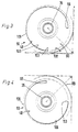
- a vortex 54 is formed transverse to the central axis 58 of the dip tubes 35.
- a wall layer flow consisting of meridian components is formed in the area of the main flow channel bend 90 (FIG. 2).
- the coarse separation zone 98 is located on the main flow channel bend 90, the solids separated out here by discharge gaps 78 to be formed in the swirl chamber bottoms 91, 92 can be dissipated.
- a fine separation zone is formed at the transition from the swirl chamber bottoms 91, 92 to the immersion tubes 35.
- the trumpet-type immersion tubes 35 shown in FIG. 1 are distinguished by various advantages.
- the gentler flow guidance when deflecting the meridian flow leads to lower radial angular momentum losses and to an improvement in the separation performance of the vortex chamber 50 in comparison to vortex chambers with cylindrical dip tubes.
- the immersion tubes 35 are designed with a progressively increasing wall curvature in the axial planes at the outlet section, the local angular momentum losses are further reduced, the flow being additionally loaded only with weak meridian flow deflections in the zones of highest flow velocities.
- the wall flow therefore only has to drive a smaller vortex volume. This reduces dissipative pressure loss components in the flow.
- the result of this is that the output angular momentum, which develops from an essentially straight flow with an almost tangential peripheral entry into the circulating flow, releases more impulse components to accelerate the wall flow.
- the volume reduction in the vortex flow field leads to shorter particle transport routes for the particles separated in the fine separation zone 100 in axial planes through the field of the vortex 54. This allows these particles to be removed from the vortex chamber 50 more quickly, as a result of which the Separation process is simplified.
- the radial secondary flow 104 on the swirl chamber bottoms 91, 92 also has a concentrating effect because of the small inward displacement forces. This occurs because the particles on the main flow channel bend 90 of the main flow channel 69 are moved approximately at the continuum speed present there and thereby flow into the zone of the bottom sink flow at a higher speed than they are moved there themselves.
- the radial reduction of the plane angular momentum transport zone in the area of the vortex chamber bottoms 91, 92 with simultaneous restriction to outer radius areas with weaker cross-sectional reduction effects brings about a reduction in the local angular momentum losses in the bottom sink flow. As a result, the concentration disadvantageous for the angular momentum is reduced.
- the surfaces of the vortex chamber bottoms 91, 92 also form zones which are ineffective for the secondary flow, since in them the displacement forces for the particles are radially and rectified with the meridian flow.
- the reduction of the separation effective floor areas by the immersion tubes 35 thus increases the separation efficiency of the swirl chamber 50.
- an increase in the highly separation effective fine separation zones 100 is achieved by the immersion tubes 35.
- the separation effect begins at the flat end of the meridian flow where the wall profile curvature of the dip tubes 35 begins.
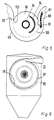
- the arrangement of the contact zone 109 between the main flow in the main flow channel 69 and the vortex 54 is of particular importance.
- the position of the contact zone 109 influences the rotational strength of the vortex field and thus the increase in the separation and separation efficiency of the vortex chamber 50.
- the high kinetic flow energy of the flow in the immersion tubes 35 must be converted back into pressure before the flow exits them.
- I k is the momentum component of the bottom layer flow that enters the vortex chamber as a driving angular momentum from the high-energy main flow.
- I m is a secondary momentum component of the bottom layer flow circulating within the vortex chamber 50. Both impulse components penetrate the bottom layer flow in spirally narrowing zones with continuous impulse strength compensation by mixing. A large relative contact arc length therefore causes the I k zones to be enlarged and the I m zones to be smaller, as a result of which the immersion tube 35 larger rotational speeds can be achieved (Fig. 2).
- a rotational symmetry of the flow on the contact zone 109 should be aimed for.
- the local flow cross sections of the main flow channel 69 decrease uniformly in the main flow direction such that a constant or at least approximately constant mean main flow rate is obtained in the main flow channel 69. This then causes constant or approximately constant circumferential speeds at the periphery of the vortex 54 in the region of the contact zone 109.
- rotationally symmetrical or largely rotationally symmetrical circumferential and radial speed distributions are achieved in the bottom layer flow.
- FIG. 3 shows the spiral curvatures of the main flow channel arch 90 and the swirl chamber arch 106 in comparison to the reference circle 108 of the main flow channel arch and the reference circle 105 of the swirl chamber 50.
- the main flow is cut from the leading edge 103 by the spiral curvature of the cylinder jacket 48. This becomes part of the high-energy main flow
- the vortex 54 is supplied over the entire length of the leading edge 103, which thereby also receives a driving rotary flow impulse on the vortex chamber jacket. Due to the spiral curvatures of the cylinder jacket 90 of the main flow channel 69 and the cylinder jacket 48 of the swirl chamber 50, a largely rotational symmetry of the entire swirl chamber rotary flow can be generated, which starts from the swirl axis of rotation, which corresponds to the central axis 58 of the swirl.
- the swirl chamber 50 can also be designed such that the main flow channel arch 90 is circular and only the swirl chamber arch 106 is spirally curved. As a result, swirl chambers 50 with shorter contact arc lengths of the contact zone 109 are possible, which can offer advantages in the design of series connections of swirl chambers 50 and in production.
- the vertical secondary velocities on both sides of the trailing edge 66 are directed in the same direction and are of the same size locally. As shown in FIG. 5, this is achieved in that the wall supplied to the trailing edge 66 from the main flow channel 69 also has a concave cylindrical shape. In this case, the trailing edge 66 flows into two concave curved wall layer flows both from the vortex 54 and from the main flow channel 69.
- the cylinder jacket 48 of the swirl chamber 50 can be spirally curved, such as, for. B. logarithmically spirally curved (Fig. 6).
- the mean inlet flow velocity in the jacket wall layer flow is kept approximately constant as the circumferential speed or is increased in the circumferential direction of the flow pattern, provided the radial distances of the jacket wall layer flow from the vortex rotation axis decrease.
- the influence of the braking of the wall friction is compensated for by the spiral guidance of the jacket wall layer flow with a decreasing radius of curvature. Since the spiral flow of the cylinder jacket 48 increases the corner flow velocities at the discharge gaps 78, the discharge and separation effect of the swirl chamber separator 10 is also increased.
- a pre-separator channel 49 which has the same overall height as the separator housing 52, is provided in front of the main gas flow inlet opening of the main flow channel 69.
- the pre-separator channel 49 is rectangular in cross section. Discharge gaps 78 can be provided at all corner flow zones of the pre-separator channel 49 which are concave for the main flow and which reinforce the pre-separation.
- the rectangular flow cross sections in the pre-separator channel 49 can either be kept constant or continuously narrow in accordance with the spiral turns in the main flow direction. This would accelerate the pre-separator flow until it enters the swirl chamber 50, which is equipped with a spiral cylinder jacket 48, so that the separation efficiency increases.
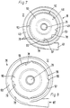
- FIG. 8 shows a swirl chamber separator 12 designed as a spiral direct separator 76, in which the raw gas is fed to the swirl chamber 50 via a plurality of tangential entry gaps 56 via the raw gas inlet 87.
- the vortex 54 is distanced from the main flow channel 69 by flow guide lamellae 57.
- the individual inlet gaps 56 are each arranged between two flow guide lamellae 57, which together form a distributor housing 55.
- the inlet gaps 56 are arranged parallel to the vortex axis, have the same gap widths and extend over the entire height of the vortex chamber 50.
- the separation and separation capacities increase with the number of inlet gaps 56.
- the flow guide fins 57 are expediently of the same design.
- the main flow channel 69 can, as shown in FIG. 8, be designed such that a circulating distributor flow is formed. However, it is possible to arrange the number of gaps and the flow guide fins 57 in such a way that that the distributor flow ends in one entry gap 56 after one revolution or less.
- discharge gaps 78 can be formed in all the corner zones concavely curved to the local primary flow zones in the vortex as well as in the distributor housing in the flat housing bottoms in order to utilize the separation effect of the secondary layer flows strongly curved in these corners as far as possible.
- the spiral direct separator can be connected to a dust bunker 80 via the discharge gaps 78.
- FIG. 9 shows a vortex chamber separator 13 in which a plurality of circular guide vane rings are arranged in the radial direction of the central axis 58 of the vortex 54 surrounding it. These have different reference radii and consist of uniformly distributed curved flow guide plates 57. An inlet gap 56 is formed between the individual flow guide plates 57. Discharge gaps 78 can be arranged in the flat housing bottoms at all concave flow corners including the outer spiral-cylindrical housing casing, so that an increased dust discharge effect is achieved in the distributor housing 55.
- the flow guide lamellae 57 in the swirl chamber separator 13 can be designed as sheet metal blades or guide plates, since the influence of the thickness of a profile would have only a slight influence on the flow.
- the flow guide fins 57 are also spirally or logarithmically spirally curved.
- the setting on each guide vane ring 59 to form a rotationally symmetrical spiral primary flow takes place in accordance with the respective local reference radii.
- the spiral curvatures aimed for the flow guide fins 57 can also be approximated here by circular arcs.
- FIG. 10 shows a swirl chamber separator 14 which has three swirl chambers 50 which are arranged in a common separator housing 52.
- the main flow channel 69 is guided around the swirl chambers 50, the flow cross section of the main flow channel 69 being reduced in sections after each swirl chamber 50 for reasons of continuity in the flow direction.
- curved baffles 61 or baffles 62 are arranged, possibly with a thickness distribution.
- the guide plates 61 or guide profiles 62 are spirally or logarithmically curved, but can also be designed in the shape of a circular arc and arranged spirally.
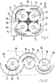
- the swirl chamber separator 15 shown in FIG. 11 as a compact arrangement of four swirl chambers 50 likewise has a circulating main gas stream 60.
- 14 guide profiles 62 are arranged as in the swirl chamber separator. These are designed such that the surface of the corresponding guide profile 62 facing the respective vertebra 54 is spirally curved and the convex outer surface 63 of the guide profile 62 is curved in the shape of a circular arc.
- the lugs 64 of the guide profiles 62 are shaped in such a way that for each swirl chamber 50 with the guide surface 65 to the trailing edge 66, an inflow section 67 with a cross section that decreases in the flow direction is formed.
- Vortex chamber separators 14 and 15 can be varied insofar as the last vortex chamber 50 in the flow direction can be designed as a direct separator with a flow inlet. Since there is no more raw gas outlet at this point, there is no circulating distributor flow in such a case.
- the vortex chambers 50 can also be connected directly to one another in different geometries as a series connection.
- the vortex chamber separator 16 which is designed as a series connection 68 of vortex chambers 50, offers a particular advantage of structural simplification without disturbing the flow of the vortex chambers (FIG. 12).
- the vortex chambers 50 are the same and aligned so that their central axes are aligned with each other on the same plane.
- the main flow channel 69 is from the respective swirl chamber through a guide profile 62 distanced with a contact arc angle of approx. 180 °.
- the free flow section of the main flow channel 69 is continuously reduced after each swirl chamber 50.
- the guide profiles 62 are spirally curved on the concave side and curved in a circular arc on the convex side. Since the cross section of the main flow channel 69 is reduced in the direction of flow, the swirl chamber row is wedge-shaped, which offers advantages that can be used in construction.
- the swirl chamber separator 17 according to FIG. 13 consists of three series connections 68, two of which are arranged parallel to one another, while the third is oriented in opposite directions.
- the main flow channel 69 opens into two series connections 68, which open together into a return channel 111.
- the third series circuit the output of which is connected to the main flow channel 69, is acted upon by the latter.
- the swirl chamber separator 17 can also be varied such that only two or else three series circuits 68 connected in parallel are connected on the output side to a further series arrangement.
- Discharge gaps 78 can also be provided in the swirl chamber separator 17.
- the further elementary row shown in FIG. 14 can also be formed from the series circuit 68 with directly separating vortex chambers 50.
- the respective contact arc angle is designed as large as possible.
- the vortex chambers 50 then lie in a tight packing on a loop-shaped main flow channel 69.
- the lost construction volumes are relatively small in this embodiment.
- guide profiles 62 can also be used.
- the series circuit 70 as a compact swirl chamber separator 18.
- 15 shows a further embodiment of a swirl chamber separator 19, which consists of three swirl chambers 50 connected in series with a decreasing diameter.
- Such a series connection 71a of vortex chambers 50 can be used in various ways to form apparatuses or systems with elementary rows arranged in parallel in circular sectors.
- cyclically radial series connections 70 of two swirl chambers 50 are arranged between an outer annular main flow channel 69 and a central swirl chamber 50, which can be designed as an end separator 74.
- the main flow channel 69 can end at a series connection 71 or can be designed such that a circulating distributor flow is created.
- Discharge gaps 78 can be provided on the concave flow corner zones of the main flow channel 69, likewise in the swirl chambers 50. It is particularly advantageous that, in the case of cyclical parallel connections of the swirl chamber element rows, a streamlined and space-saving coupling possibility with a single end separator is provided, which, for. B. can be a spiral direct separator 76. With regard to its main flow channel 69, this is designed such that multiple angular momentum initiation is possible.
- the vortex chamber separator 20 is characterized by a particularly compact design and can be produced from standardized components with only a small construction volume lost.
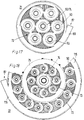
- a swirl chamber separator 21 it is also possible to design a swirl chamber separator 21 in such a way that a number of series connections 72 of the same swirl chambers 50 are cyclically connected peripherally in parallel (FIG. 17).
- the series circuits 72 are connected to a swirl chamber 50 as an end separator 74.
- This end separator can also be designed as a spiral direct separator 76.
- the main flow channel 69 is circular around the arrangement of the series connections 72, so that a circulating flow is achieved.
- the vortex chamber rows 72 can consist of directly separating vortex chambers 50.
- the vortex chamber separator 22 consists of two vortex chamber ring stages 73 which are arranged concentrically to one another and which are surrounded on the outside by the distributor channel 115.
- the outer swirl chamber ring stage 73 has swirl chambers 50 arranged parallel to one another, which are connected on the inside to an intermediate distributor channel 75.
- the vortex chambers 50 of the inner vortex chamber ring stage 73 are connected to the end separator 74 via this.
- This vortex chamber separator 22 is extraordinarily flexible in adapting to the particular application due to the large number of possible interconnections of vortex separators with vortex chambers 50. It is therefore not necessary to completely cover each vortex chamber ring stage 73 with vortex chambers 50. Rather, 50 dummy pieces or dummy ring elements can be used instead of individual swirl chambers, which are not shown in detail. It is therefore possible to create 22 cyclic modular systems with standard parts based on the principle of the vortex chamber separator.
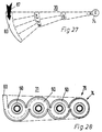
- FIG. 21 the continuity-related wedge-shaped convergence of the elementary row boundaries is shown using the example of the swirl chamber separator 16.
- group switching of different types can be carried out, which lead to vortex chamber separators corresponding to the type indicated in FIGS. 22 to 27.
- the grouping ratios depend on the total suction ratio of the respective elementary row of open simple or direct separating vortex chambers 50.
- the group circuits enable the advantage that standardized elementary rows of vortex chambers 50 can be used for the system design.
- the elementary series connections which decrease in stages are ultimately connected to an end separator, which can be a spiral direct separator 76 or else another direct separator.
- an end separator which can be a spiral direct separator 76 or else another direct separator.
- a fabric or electrostatic precipitator as the final separator, which can be made relatively small due to the preceding cleaning process.
- the residual volume flow of the last stage in the case of directly separating swirl chamber element rows can also be returned to the total raw gas inlet.
- the return volume flow can likewise be introduced between two stages of swirl chamber element rows to be selected. Both circulation circuits and partial circulation circuits are thus possible.
- This swirl chamber separator 31 can also be provided with guide plates 61 or guide profiles 62 in the area of the swirl chambers 50.
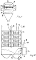
- FIG. 29 shows a dedusting system 32 which consists of a parallel connection of closed, direct separating swirl chamber element rows 119 corresponding to the swirl chamber separator 31 and a dust bunker 80.
- Each swirl chamber elementary row 119 consists of a series connection 68, 71, 71a of swirl chambers 50, which is designed such that its housing 116 tapers in a wedge shape towards the outlet end section for reasons of continuity.
- the individual swirl chamber element rows are connected to the total raw gas inlet channel 83 in parallel to one another in such a way that the spaces 118 between the individual swirl chamber element rows 119 likewise widen in a wedge shape to their end sections 117.
- the free space achieved in this way supports the function of the bunker suction device 81, which is formed on the dust bunker 80.
- the dust bunker 80 is formed by a housing 79, on the lower section of which funnels 110 are arranged. The dust accumulated in the housing 79 can be removed via these funnels.
- the bunker suction device 81 is provided on one side wall 35 of the housing 79. By means of this, a smaller volume flow is sucked out of the dust bunker 80 in order to generate a discharge flow in the discharge gaps 78 of the directly separating vortex chamber element rows, which are not shown in any more detail. This improves the dust discharge from the respective vortex chambers 50 and thus their separation performance.
- the wedge-shaped convergence of the housing boundaries of the elementary rows enables wedge-shaped gaps between the individual swirl chamber separators 31, as a result of which the gap discharge flow initiated by the bunker suction is evened out.
- three spiral direct separators are located on a total raw gas inlet channel 83 76 connected.
- a bunker suction device 81 is provided on the housing 79 of the dust bunker 80, the flow outlet 82 of which is connected to the total raw gas inlet channel 83 in the region of the raw gas inlet 87.
- An impact separator 85 is provided in front of the suction opening 84 of the bunker suction device 81. This plate-shaped impact separator 85 reduces the dust content of the volume flow to be extracted from the dust bunker 80 by the bunker suction device 81. The separating effect of the impact separator 85 is achieved by the strongly curved flow deflection at the plate edges.
- a direct separating system corresponding to the dedusting system 32, 33 can be provided, in which the swirl diffusers of the immersion tubes 35 located outside the separator housing 52 end in easy-to-create outer suction collecting housings for the clean gas volume flow 96.
Landscapes
- Chemical & Material Sciences (AREA)
- Chemical Kinetics & Catalysis (AREA)
- Physics & Mathematics (AREA)
- Thermal Sciences (AREA)
- Cyclones (AREA)
Applications Claiming Priority (3)
| Application Number | Priority Date | Filing Date | Title |
|---|---|---|---|
| DE3615747 | 1986-05-09 | ||
| DE19863615747 DE3615747A1 (de) | 1986-05-09 | 1986-05-09 | Verfahren zum trennen und/oder abscheiden von festen und/oder fluessigen partikeln mit einem wirbelkammerabscheider mit tauchrohr und wirbelkammerabscheider zur durchfuehrung des verfahrens |
| EP87106289A EP0249023B1 (de) | 1986-05-09 | 1987-04-30 | Wirbelkammerabscheider |
Related Parent Applications (1)
| Application Number | Title | Priority Date | Filing Date |
|---|---|---|---|
| EP87106289.9 Division | 1987-04-30 |
Publications (2)
| Publication Number | Publication Date |
|---|---|
| EP0475467A1 EP0475467A1 (de) | 1992-03-18 |
| EP0475467B1 true EP0475467B1 (de) | 1996-07-10 |
Family
ID=6300534
Family Applications (2)
| Application Number | Title | Priority Date | Filing Date |
|---|---|---|---|
| EP91120013A Expired - Lifetime EP0475467B1 (de) | 1986-05-09 | 1987-04-30 | Wirbelkammerabscheider |
| EP87106289A Expired - Lifetime EP0249023B1 (de) | 1986-05-09 | 1987-04-30 | Wirbelkammerabscheider |
Family Applications After (1)
| Application Number | Title | Priority Date | Filing Date |
|---|---|---|---|
| EP87106289A Expired - Lifetime EP0249023B1 (de) | 1986-05-09 | 1987-04-30 | Wirbelkammerabscheider |
Country Status (5)
| Country | Link |
|---|---|
| US (3) | US4801310A (enExample) |
| EP (2) | EP0475467B1 (enExample) |
| JP (1) | JPS62289252A (enExample) |
| AT (2) | ATE96687T1 (enExample) |
| DE (3) | DE3615747A1 (enExample) |
Families Citing this family (103)
| Publication number | Priority date | Publication date | Assignee | Title |
|---|---|---|---|---|
| AT392425B (de) * | 1989-08-23 | 1991-03-25 | Voest Alpine Krems | Verfahren zum abtrennen von wenigstens einem stoff aus einem fluessigen oder gasfoermigen medium |
| US5236587A (en) * | 1989-05-18 | 1993-08-17 | Josef Keuschnigg | Process and apparatus for the separation of materials from a medium |
| FI902329A7 (fi) * | 1989-05-18 | 1990-11-19 | Josef Keuschnigg | Erotusmenetelmä ja -laite |
| AT391426B (de) * | 1989-05-18 | 1990-10-10 | Voest Alpine Krems | Verfahren und vorrichtung zum abtrennen von stoffen aus einem stroemenden medium |
| US5033915A (en) * | 1989-10-27 | 1991-07-23 | The Babcock & Wilcox Company | Low pressure drop steam/water conical cyclone separator |
| AU112161S (en) | 1990-03-23 | 1991-09-23 | Sundstrom Safety A B | A section |
| SE465813B (sv) * | 1990-03-23 | 1991-11-04 | Sundstrom Safety Ab | Cyklonkammare med droppavskiljare |
| DE4010238A1 (de) * | 1990-03-30 | 1991-10-02 | Bielefeldt Ernst August | Wirbelkammerabscheider |
| US5078880A (en) * | 1990-09-12 | 1992-01-07 | Water Technology Assessment Group | Vortex desalination system |
| US5393502A (en) * | 1993-09-07 | 1995-02-28 | International Purification Systems, Inc. | Solubilizing apparatus |
| US5553591A (en) * | 1994-06-20 | 1996-09-10 | Rockwell International Corp. | Engine power enhancement/pollution control system utilizing vortex air separator |
| US5517978A (en) * | 1994-06-20 | 1996-05-21 | Rockwell International Corporation | Pollution control system for an internal combustion engine |
| DE29501148U1 (de) * | 1995-01-25 | 1995-07-20 | Bielefeldt, Ernst-August, 24582 Bordesholm | Einrichtung zur Stofftrennung mittels Fliehkraft |
| DE19502202A1 (de) * | 1995-01-25 | 1996-08-22 | Ernst August Bielefeldt | Verfahren und Einrichtung zur Stofftrennung mittels Fliehkraft |
| RU2128554C1 (ru) * | 1997-03-04 | 1999-04-10 | Тувинский институт комплексного освоения природных ресурсов СО РАН | Способ и устройство для разделения твердых материалов с помощью тяжелой среды с использованием центробежной силы |
| RU2157715C2 (ru) * | 1998-05-29 | 2000-10-20 | Мильчаков Владимир Игоревич | Способ разделения неустойчивых эмульсий и устройство для его реализации |
| US6277278B1 (en) | 1998-08-19 | 2001-08-21 | G.B.D. Corp. | Cyclone separator having a variable longitudinal profile |
| US6312594B1 (en) * | 1998-08-19 | 2001-11-06 | G.B.D. Corp. | Insert for a cyclone separator |
| US6168716B1 (en) * | 1998-08-19 | 2001-01-02 | G.B.D. Corp. | Cyclone separator having a variable transverse profile |
| US6129775A (en) * | 1998-08-19 | 2000-10-10 | G.B.D. Corp. | Terminal insert for a cyclone separator |
| RU2158163C2 (ru) * | 1998-08-20 | 2000-10-27 | Мильчаков Владимир Игоревич | Способ разделения неустойчивых эмульсий и устройство для его реализации |
| US7244396B2 (en) * | 1999-04-06 | 2007-07-17 | Uab Research Foundation | Method for preparation of microarrays for screening of crystal growth conditions |
| US6565321B1 (en) | 1999-05-21 | 2003-05-20 | Vortex Holding Company | Vortex attractor |
| US6595753B1 (en) | 1999-05-21 | 2003-07-22 | A. Vortex Holding Company | Vortex attractor |
| US6428589B1 (en) | 2000-09-29 | 2002-08-06 | Royal Appliance Mfg. Co. | Two-stage particle separator for vacuum cleaners |
| US6645382B1 (en) * | 2000-11-13 | 2003-11-11 | George E. Wilson | Energy-efficient head cell entry duct |
| KR100438284B1 (ko) * | 2001-05-02 | 2004-07-02 | 병 도 김 | 볼텍스 튜브 이론을 이용한 배기가스 정화장치 |
| AU2003240105A1 (en) * | 2002-06-18 | 2003-12-31 | Awazel Waterproofing Company | Extraction methods and apparatus |
| CA2471048C (en) | 2002-09-19 | 2006-04-25 | Suncor Energy Inc. | Bituminous froth hydrocarbon cyclone |
| US7736501B2 (en) | 2002-09-19 | 2010-06-15 | Suncor Energy Inc. | System and process for concentrating hydrocarbons in a bitumen feed |
| US6935513B2 (en) * | 2002-12-18 | 2005-08-30 | Molecular Separation Technologies, Llc | Method and apparatus for mixture separation |
| RU2260473C2 (ru) * | 2003-11-17 | 2005-09-20 | Ярославцев Виктор Федорович | Устройство для обогащения полезных ископаемых |
| US7048783B2 (en) * | 2004-04-13 | 2006-05-23 | Oreck Holdings, Llc | Vacuum cleaner air/liquid separator |
| RU2287359C2 (ru) * | 2004-11-30 | 2006-11-20 | Открытое акционерное общество "Минерально-химическая компания "ЕвроХим"(ОАО "МХК "ЕвроХим") | Вихревой аппарат для проведения физико-химических процессов с нисходящим потоком фаз |
| RU2331454C2 (ru) * | 2004-12-02 | 2008-08-20 | Открытое акционерное общество "Татнефть" им. В.Д. Шашина | Система комплексной подготовки продукции скважин |
| US8746463B2 (en) * | 2006-05-22 | 2014-06-10 | Contech Engineered Solutions LLC | Apparatus for separating particulate from stormwater |
| US7842113B2 (en) * | 2006-09-20 | 2010-11-30 | Babcock & Wilcox Power Generation Group, Inc. | Extended water level range steam/water conical cyclone separator |
| US8735337B2 (en) * | 2007-03-13 | 2014-05-27 | Food Safety Technology, Llc | Aqueous ozone solution for ozone cleaning system |
| US9068149B2 (en) * | 2007-03-14 | 2015-06-30 | Food Safety Technology, Llc | Ozone cleaning system |
| US7637699B2 (en) * | 2007-07-05 | 2009-12-29 | Babcock & Wilcox Power Generation Group, Inc. | Steam/water conical cyclone separator |
| US9174845B2 (en) | 2008-07-24 | 2015-11-03 | Food Safety Technology, Llc | Ozonated liquid dispensing unit |
| US9522348B2 (en) | 2008-07-24 | 2016-12-20 | Food Safety Technology, Llc | Ozonated liquid dispensing unit |
| DK2373585T3 (en) | 2008-12-01 | 2017-07-10 | Veolia Water Solutions & Tech | Method and device for removal of particulate matter in sewage |
| US7887613B2 (en) * | 2009-02-10 | 2011-02-15 | Panasonic Corporation Of North America | Vacuum cleaner having dirt collection vessel with toroidal cyclone |
| NL2002691C2 (en) * | 2009-03-31 | 2010-10-04 | Romico Hold A V V | Method for separating a medium mixture into fractions. |
| CA2764522C (en) * | 2009-07-02 | 2015-09-15 | The Governors Of The University Of Alberta | Particle classifier |
| US8276669B2 (en) * | 2010-06-02 | 2012-10-02 | Halliburton Energy Services, Inc. | Variable flow resistance system with circulation inducing structure therein to variably resist flow in a subterranean well |
| US9109423B2 (en) | 2009-08-18 | 2015-08-18 | Halliburton Energy Services, Inc. | Apparatus for autonomous downhole fluid selection with pathway dependent resistance system |
| US8235128B2 (en) * | 2009-08-18 | 2012-08-07 | Halliburton Energy Services, Inc. | Flow path control based on fluid characteristics to thereby variably resist flow in a subterranean well |
| US8893804B2 (en) * | 2009-08-18 | 2014-11-25 | Halliburton Energy Services, Inc. | Alternating flow resistance increases and decreases for propagating pressure pulses in a subterranean well |
| CA2689021C (en) | 2009-12-23 | 2015-03-03 | Thomas Charles Hann | Apparatus and method for regulating flow through a pumpbox |
| US8708050B2 (en) | 2010-04-29 | 2014-04-29 | Halliburton Energy Services, Inc. | Method and apparatus for controlling fluid flow using movable flow diverter assembly |
| AU2015201733B2 (en) * | 2010-06-02 | 2016-10-20 | Halliburton Energy Services, Inc. | Variable flow resistance with circulation inducing structure therein to variably resist flow in a subterranean well |
| US8261839B2 (en) * | 2010-06-02 | 2012-09-11 | Halliburton Energy Services, Inc. | Variable flow resistance system for use in a subterranean well |
| US8356668B2 (en) * | 2010-08-27 | 2013-01-22 | Halliburton Energy Services, Inc. | Variable flow restrictor for use in a subterranean well |
| US8430130B2 (en) | 2010-09-10 | 2013-04-30 | Halliburton Energy Services, Inc. | Series configured variable flow restrictors for use in a subterranean well |
| US8950502B2 (en) | 2010-09-10 | 2015-02-10 | Halliburton Energy Services, Inc. | Series configured variable flow restrictors for use in a subterranean well |
| US8851180B2 (en) | 2010-09-14 | 2014-10-07 | Halliburton Energy Services, Inc. | Self-releasing plug for use in a subterranean well |
| CN102008872A (zh) * | 2010-10-27 | 2011-04-13 | 常熟理工学院 | 扇形螺旋叶片 |
| US8387662B2 (en) | 2010-12-02 | 2013-03-05 | Halliburton Energy Services, Inc. | Device for directing the flow of a fluid using a pressure switch |
| US8602106B2 (en) | 2010-12-13 | 2013-12-10 | Halliburton Energy Services, Inc. | Downhole fluid flow control system and method having direction dependent flow resistance |
| US8555975B2 (en) | 2010-12-21 | 2013-10-15 | Halliburton Energy Services, Inc. | Exit assembly with a fluid director for inducing and impeding rotational flow of a fluid |
| MY164163A (en) | 2011-04-08 | 2017-11-30 | Halliburton Energy Services Inc | Method and apparatus for controlling fluid flow in an autonomous valve using a sticky switch |
| US8678035B2 (en) | 2011-04-11 | 2014-03-25 | Halliburton Energy Services, Inc. | Selectively variable flow restrictor for use in a subterranean well |
| US8985150B2 (en) | 2011-05-03 | 2015-03-24 | Halliburton Energy Services, Inc. | Device for directing the flow of a fluid using a centrifugal switch |
| US9212522B2 (en) * | 2011-05-18 | 2015-12-15 | Thru Tubing Solutions, Inc. | Vortex controlled variable flow resistance device and related tools and methods |
| US8453745B2 (en) * | 2011-05-18 | 2013-06-04 | Thru Tubing Solutions, Inc. | Vortex controlled variable flow resistance device and related tools and methods |
| US8714262B2 (en) | 2011-07-12 | 2014-05-06 | Halliburton Energy Services, Inc | Methods of limiting or reducing the amount of oil in a sea using a fluid director |
| US8584762B2 (en) | 2011-08-25 | 2013-11-19 | Halliburton Energy Services, Inc. | Downhole fluid flow control system having a fluidic module with a bridge network and method for use of same |
| EP2773842A4 (en) | 2011-10-31 | 2015-08-19 | Halliburton Energy Services Inc | AUTONOMOUS FLOW REGULATION DEVICE COMPRISING A PLATE FORMING VALVE FOR SELECTING FLUID IN WELL BOTTOM |
| MY167551A (en) | 2011-10-31 | 2018-09-14 | Halliburton Energy Services Inc | Autonomous fluid control device having a reciprocating valve for downhole fluid selection |
| US8739880B2 (en) | 2011-11-07 | 2014-06-03 | Halliburton Energy Services, P.C. | Fluid discrimination for use with a subterranean well |
| US9506320B2 (en) | 2011-11-07 | 2016-11-29 | Halliburton Energy Services, Inc. | Variable flow resistance for use with a subterranean well |
| US8684094B2 (en) | 2011-11-14 | 2014-04-01 | Halliburton Energy Services, Inc. | Preventing flow of undesired fluid through a variable flow resistance system in a well |
| EP2748469B1 (en) | 2011-11-22 | 2019-12-25 | Halliburton Energy Services, Inc. | An exit assembly having a fluid diverter that displaces the pathway of a fluid into two or more pathways |
| BR112014014472A2 (pt) * | 2011-12-16 | 2017-06-13 | Halliburton Energy Services Inc | dispositivo de controle de fluxo |
| CN103998854B (zh) * | 2011-12-21 | 2016-10-12 | 哈里伯顿能源服务公司 | 流动影响装置 |
| MY167298A (en) * | 2012-01-27 | 2018-08-16 | Halliburton Energy Services Inc | Series configured variable flow restrictors for use in a subterranean well |
| AT512151B1 (de) | 2012-05-24 | 2013-06-15 | A Tec Holding Gmbh | Vorrichtung zum Abtrennen von Stoffen aus einem Medium |
| CN102784726A (zh) * | 2012-07-18 | 2012-11-21 | 樊荣 | 一种旋风式气水分离器 |
| US9404349B2 (en) | 2012-10-22 | 2016-08-02 | Halliburton Energy Services, Inc. | Autonomous fluid control system having a fluid diode |
| US9695654B2 (en) | 2012-12-03 | 2017-07-04 | Halliburton Energy Services, Inc. | Wellhead flowback control system and method |
| US9127526B2 (en) | 2012-12-03 | 2015-09-08 | Halliburton Energy Services, Inc. | Fast pressure protection system and method |
| US9370783B2 (en) * | 2014-03-28 | 2016-06-21 | Uop Llc | Apparatuses and methods for gas-solid separations using cyclones |
| CN104929575A (zh) * | 2015-05-26 | 2015-09-23 | 西南石油大学 | 相控阀 |
| EP3117904B1 (de) | 2015-07-17 | 2020-08-19 | MCI Management Center Innsbruck - Internationale Hochschule GmbH | Abscheidevorrichtung für teilchen aus einem fluidstrom |
| US9316065B1 (en) | 2015-08-11 | 2016-04-19 | Thru Tubing Solutions, Inc. | Vortex controlled variable flow resistance device and related tools and methods |
| WO2017037714A1 (en) | 2015-09-03 | 2017-03-09 | Aqua Hd Separation & Filtration Systems Ltd | A duct for use in a system for separating particles suspended in a fluid, and a method of designing such duct |
| DK3419731T3 (da) * | 2016-01-25 | 2024-06-17 | Hydrocon Gmbh | Separator til adskillelse af fast materiale fra et fluid |
| US10569198B2 (en) | 2016-07-19 | 2020-02-25 | Eaton Intelligent Power Limited | Fluid separator |
| IL251036A0 (en) | 2017-03-08 | 2017-06-29 | Aqua Hd Separation And Filtration Systems Ltd | A system and a method for separation of particles suspended in a fluid |
| US10583382B2 (en) * | 2017-10-04 | 2020-03-10 | Bendix Commercial Vehicle Systems Llc | Effluent processing apparatus for a vehicle air brake charging system |
| KR101863026B1 (ko) * | 2018-01-04 | 2018-05-30 | 주식회사 포스코휴먼스 | 다중 사이클론을 이용한 집진 장치 |
| EP3539638B1 (en) * | 2018-03-14 | 2021-02-24 | Tata Consultancy Services Limited | Integrated apparatus for mixing and separating fluid phases and method therefor |
| EP3877074A4 (en) * | 2018-06-01 | 2023-09-13 | MobiAir Pte. Ltd. | DEVICE AND METHOD FOR CLEANING A FLUID CONTAINING PARTICLES USING A LOW ENERGY MULTIPLE FLOW DIVIDER TECHNOLOGY WITHOUT FILTER MEDIA |
| AU2020210766B2 (en) * | 2019-01-25 | 2023-08-31 | Sharkninja Operating Llc | Cyclonic separator for a vacuum cleaner and a vacuum cleaner having the same |
| CN110882560B (zh) * | 2019-12-03 | 2021-06-11 | 东北石油大学 | 一种间歇式旋流分离装置 |
| US12134048B2 (en) | 2020-06-15 | 2024-11-05 | Eric Larin | Oil and grit separator system with twin vortex |
| DE102022106285B4 (de) | 2022-03-17 | 2025-03-06 | Messer Se & Co. Kgaa | Vorrichtung und Verfahren zum kontinuierlichen Gasaustausch in einem Strom eines Fluidgemischs |
| CN114748938A (zh) * | 2022-05-18 | 2022-07-15 | 西安工业大学 | 一种城市建筑污水处理装置 |
| CN114871078A (zh) * | 2022-05-18 | 2022-08-09 | 三一技术装备有限公司 | 烘箱新风系统 |
| CN115487699B (zh) * | 2022-09-01 | 2024-05-03 | 同济大学 | 一种土壤中污染物高压涡流高效分离装置 |
| CN116688654B (zh) * | 2023-08-04 | 2023-10-20 | 江苏河海新动力有限公司 | 除雾件及除雾器 |
Family Cites Families (21)
| Publication number | Priority date | Publication date | Assignee | Title |
|---|---|---|---|---|
| DE640308C (de) * | 1936-12-30 | Metallgesellschaft Akt Ges | Fliehkraftstaubabscheider | |
| DE324260C (de) * | 1918-10-18 | 1920-08-23 | Emil Schierholz | Vorrichtung zum Auswaschen bzw. Ausscheiden mechanischer Beimengungen aus Gasen, Daempfen und Fluessigkeiten |
| DE329779C (de) * | 1919-08-19 | 1920-11-29 | Emil Schierholz | Zyklonartige Vorrichtung zum Ausscheiden fester Beimengungen aus Gasen, Daempfen und Fluessigkeiten |
| GB477621A (en) * | 1936-07-14 | 1938-01-04 | Jens Orten Boving | Improvements in cyclone dust separators |
| NL78361C (enExample) * | 1950-03-09 | |||
| LU31402A1 (enExample) * | 1951-04-22 | |||
| DE882543C (de) * | 1951-10-28 | 1953-07-09 | Alfred P Konejung | Vorrichtung zum Abscheiden von Fluessigkeiten aus Daempfen und Gasen durch Fliehkraftwirkung |
| US2936043A (en) * | 1957-01-09 | 1960-05-10 | Cottrell Res Inc | Cyclonic dust collector |
| US3273320A (en) * | 1963-07-15 | 1966-09-20 | Exxon Research Engineering Co | Cyclone separator for high temperature operations |
| US3535850A (en) * | 1966-10-28 | 1970-10-27 | Hans J P Von Ohain | Centrifugal particle separator |
| SE316747B (enExample) * | 1967-10-17 | 1969-11-03 | N Wikdahl | |
| US3636682A (en) * | 1968-03-08 | 1972-01-25 | Phillips Petroleum Co | Cyclone separator |
| DE2206318C3 (de) * | 1972-02-10 | 1980-09-18 | Messerschmitt-Boelkow-Blohm Gmbh, 8000 Muenchen | Einrichtung zum Trennen und Abscheiden von in einem Medium suspendierten Stoffen mittels Fliehkraft |
| US3792573A (en) * | 1972-04-06 | 1974-02-19 | L Borsheim | Air cleaning structure |
| DE2538664C2 (de) * | 1975-08-30 | 1983-11-17 | Messerschmitt-Bölkow-Blohm GmbH, 8000 München | Einrichtung zum Abtrennen des spezifisch leichteren Anteils aus einem Strom eines mit suspendierten Stoffen beladenen Mediums |
| DE2832097C2 (de) * | 1978-07-21 | 1983-12-22 | Messerschmitt-Bölkow-Blohm GmbH, 8000 München | Verfahren und Einrichtung zum Stofftrennen mittels Fliehkraft |
| FR2356451A2 (fr) * | 1975-10-24 | 1978-01-27 | Commissariat Energie Atomique | Dispositif de separation des constituants d'un melange gazeux |
| GB1595975A (en) * | 1977-04-14 | 1981-08-19 | Summers D | Apparatus for separating particles from gases |
| JPS5432985A (en) * | 1977-08-19 | 1979-03-10 | Mitsubishi Electric Corp | Flattening method for substrate surface with protrusion |
| DE3203498C2 (de) * | 1981-02-05 | 1986-08-21 | Anton Piller GmbH & Co KG, 3360 Osterode | Abscheider für in einem Gasstrom suspendierte Feststoffe mittels Fliehkraft |
| US4578840A (en) * | 1984-06-04 | 1986-04-01 | General Resource Corp. | Mobile vacuum machine |
-
1986
- 1986-05-09 DE DE19863615747 patent/DE3615747A1/de not_active Withdrawn
-
1987
- 1987-04-30 EP EP91120013A patent/EP0475467B1/de not_active Expired - Lifetime
- 1987-04-30 DE DE87106289T patent/DE3788001D1/de not_active Expired - Fee Related
- 1987-04-30 AT AT87106289T patent/ATE96687T1/de not_active IP Right Cessation
- 1987-04-30 AT AT91120013T patent/ATE140162T1/de not_active IP Right Cessation
- 1987-04-30 DE DE3751855T patent/DE3751855D1/de not_active Expired - Fee Related
- 1987-04-30 EP EP87106289A patent/EP0249023B1/de not_active Expired - Lifetime
- 1987-05-07 US US07/047,002 patent/US4801310A/en not_active Expired - Fee Related
- 1987-05-09 JP JP62111719A patent/JPS62289252A/ja active Granted
-
1988
- 1988-10-17 US US07/258,766 patent/US4848991A/en not_active Expired - Fee Related
-
1989
- 1989-04-11 US US07/336,350 patent/US4895582A/en not_active Expired - Fee Related
Also Published As
| Publication number | Publication date |
|---|---|
| US4895582A (en) | 1990-01-23 |
| EP0249023A1 (de) | 1987-12-16 |
| DE3615747A1 (de) | 1987-11-12 |
| JPS62289252A (ja) | 1987-12-16 |
| DE3751855D1 (de) | 1996-08-14 |
| EP0475467A1 (de) | 1992-03-18 |
| US4801310A (en) | 1989-01-31 |
| US4848991A (en) | 1989-07-18 |
| DE3788001D1 (de) | 1993-12-09 |
| JPH0518630B2 (enExample) | 1993-03-12 |
| ATE140162T1 (de) | 1996-07-15 |
| EP0249023B1 (de) | 1993-11-03 |
| ATE96687T1 (de) | 1993-11-15 |
Similar Documents
| Publication | Publication Date | Title |
|---|---|---|
| EP0475467B1 (de) | Wirbelkammerabscheider | |
| EP0723813B1 (de) | Verfahren und Einrichtung zur Stofftrennung mittels Fliehkraft | |
| DE69804995T2 (de) | Zyklonabscheider | |
| EP0215075B1 (de) | Zyklonabscheider mit zwei abscheideräumen und statischen leitvorrichtungen | |
| DE2347984A1 (de) | Apparat zum abscheiden von partikeln aus gasen | |
| DE2948168A1 (de) | Apparat zum abscheiden von feststoffpartikeln aus einem gasstrom | |
| EP0014782B1 (de) | Entstaubungseinrichtung | |
| DE10247123A1 (de) | Vorrichtung zur Abscheidung von Flüssigkeit aus einem Gasstrom | |
| DE3936078C2 (de) | Drallerzeuger für Zyklonabscheider | |
| EP0398864A2 (de) | Verfahren und Vorrichtung zum Abtrennen von Stoffen aus einem Medium | |
| EP0481030B1 (de) | Wirbelkammerabscheider | |
| DE2250841B2 (de) | Fliehkraftabscheider für feste und flüssige Stoffe aus Gasen | |
| DE10044104C2 (de) | Windsichter | |
| DE69618550T2 (de) | Vielstufige Gas/Feststofftrennvorrichtung und Verfahren | |
| DE10230881A1 (de) | Wasserabscheider für Klimaanlagen | |
| DE2153398C3 (de) | Vorrichtung zum Abscheiden von festen oder flüssigen Teilchen aus Gasen | |
| DE102011078401B4 (de) | Verfahren zum zweifachen Abscheiden von Staub aus staubbeladener Saugluft | |
| DE102016004496B4 (de) | Abscheidevorrichtung sowie Verfahren zur Abscheidung von Partikeln aus einer Ansaugluft einer Brennkraftmaschine | |
| AT392425B (de) | Verfahren zum abtrennen von wenigstens einem stoff aus einem fluessigen oder gasfoermigen medium | |
| DE3626983C2 (enExample) | ||
| EP0256491A2 (de) | Fliehkraftstaubabscheider mit einer Mehrzahl von Zyklonen | |
| DE2743995A1 (de) | Wirbelrohr zur trennung von gas- oder isotopengemischen | |
| DE3509789A1 (de) | Zyklonabscheider mit zwei abscheideraeumen und statischen leitvorrichtungen | |
| DE19623178A1 (de) | Abscheider zum Abscheiden von Flüssigkeiten, insbesondere von Schadstoffen, aus einem Gasstrom | |
| DE3607023A1 (de) | Zyklonabscheider mit zwei abscheideraeumen und statischen leitvorrichtungen |
Legal Events
| Date | Code | Title | Description |
|---|---|---|---|
| PUAI | Public reference made under article 153(3) epc to a published international application that has entered the european phase |
Free format text: ORIGINAL CODE: 0009012 |
|
| 17P | Request for examination filed |
Effective date: 19911227 |
|
| AC | Divisional application: reference to earlier application |
Ref document number: 249023 Country of ref document: EP |
|
| AK | Designated contracting states |
Kind code of ref document: A1 Designated state(s): AT BE CH DE ES FR GB GR IT LI NL SE |
|
| 17Q | First examination report despatched |
Effective date: 19950103 |
|
| GRAH | Despatch of communication of intention to grant a patent |
Free format text: ORIGINAL CODE: EPIDOS IGRA |
|
| GRAA | (expected) grant |
Free format text: ORIGINAL CODE: 0009210 |
|
| AC | Divisional application: reference to earlier application |
Ref document number: 249023 Country of ref document: EP |
|
| AK | Designated contracting states |
Kind code of ref document: B1 Designated state(s): AT BE CH DE ES FR GB GR IT LI NL SE |
|
| PG25 | Lapsed in a contracting state [announced via postgrant information from national office to epo] |
Ref country code: IT Free format text: LAPSE BECAUSE OF FAILURE TO SUBMIT A TRANSLATION OF THE DESCRIPTION OR TO PAY THE FEE WITHIN THE PRESCRIBED TIME-LIMIT;WARNING: LAPSES OF ITALIAN PATENTS WITH EFFECTIVE DATE BEFORE 2007 MAY HAVE OCCURRED AT ANY TIME BEFORE 2007. THE CORRECT EFFECTIVE DATE MAY BE DIFFERENT FROM THE ONE RECORDED. Effective date: 19960710 Ref country code: GR Free format text: LAPSE BECAUSE OF FAILURE TO SUBMIT A TRANSLATION OF THE DESCRIPTION OR TO PAY THE FEE WITHIN THE PRESCRIBED TIME-LIMIT Effective date: 19960710 Ref country code: NL Free format text: LAPSE BECAUSE OF FAILURE TO SUBMIT A TRANSLATION OF THE DESCRIPTION OR TO PAY THE FEE WITHIN THE PRESCRIBED TIME-LIMIT Effective date: 19960710 Ref country code: GB Effective date: 19960710 Ref country code: FR Effective date: 19960710 |
|
| REF | Corresponds to: |
Ref document number: 140162 Country of ref document: AT Date of ref document: 19960715 Kind code of ref document: T |
|
| REF | Corresponds to: |
Ref document number: 3751855 Country of ref document: DE Date of ref document: 19960814 |
|
| PG25 | Lapsed in a contracting state [announced via postgrant information from national office to epo] |
Ref country code: SE Effective date: 19961010 |
|
| PG25 | Lapsed in a contracting state [announced via postgrant information from national office to epo] |
Ref country code: ES Free format text: LAPSE BECAUSE OF FAILURE TO SUBMIT A TRANSLATION OF THE DESCRIPTION OR TO PAY THE FEE WITHIN THE PRESCRIBED TIME-LIMIT Effective date: 19961021 |
|
| NLV1 | Nl: lapsed or annulled due to failure to fulfill the requirements of art. 29p and 29m of the patents act | ||
| EN | Fr: translation not filed | ||
| GBV | Gb: ep patent (uk) treated as always having been void in accordance with gb section 77(7)/1977 [no translation filed] |
Effective date: 19960710 |
|
| PG25 | Lapsed in a contracting state [announced via postgrant information from national office to epo] |
Ref country code: CH Free format text: LAPSE BECAUSE OF NON-PAYMENT OF DUE FEES Effective date: 19970430 Ref country code: AT Free format text: LAPSE BECAUSE OF NON-PAYMENT OF DUE FEES Effective date: 19970430 Ref country code: BE Effective date: 19970430 Ref country code: LI Free format text: LAPSE BECAUSE OF NON-PAYMENT OF DUE FEES Effective date: 19970430 |
|
| PLBE | No opposition filed within time limit |
Free format text: ORIGINAL CODE: 0009261 |
|
| STAA | Information on the status of an ep patent application or granted ep patent |
Free format text: STATUS: NO OPPOSITION FILED WITHIN TIME LIMIT |
|
| 26N | No opposition filed | ||
| REG | Reference to a national code |
Ref country code: CH Ref legal event code: PL |
|
| PG25 | Lapsed in a contracting state [announced via postgrant information from national office to epo] |
Ref country code: DE Free format text: LAPSE BECAUSE OF NON-PAYMENT OF DUE FEES Effective date: 19980101 |