EP0474569A1 - Sicherheitsvorrichtung gegen Überlauf bei einer hydraulischen Verbindung - Google Patents
Sicherheitsvorrichtung gegen Überlauf bei einer hydraulischen Verbindung Download PDFInfo
- Publication number
- EP0474569A1 EP0474569A1 EP91420302A EP91420302A EP0474569A1 EP 0474569 A1 EP0474569 A1 EP 0474569A1 EP 91420302 A EP91420302 A EP 91420302A EP 91420302 A EP91420302 A EP 91420302A EP 0474569 A1 EP0474569 A1 EP 0474569A1
- Authority
- EP
- European Patent Office
- Prior art keywords
- water
- safety device
- passage
- hydraulic connection
- pin
- Prior art date
- Legal status (The legal status is an assumption and is not a legal conclusion. Google has not performed a legal analysis and makes no representation as to the accuracy of the status listed.)
- Granted
Links
- XLYOFNOQVPJJNP-UHFFFAOYSA-N water Substances O XLYOFNOQVPJJNP-UHFFFAOYSA-N 0.000 claims abstract description 52
- 230000000694 effects Effects 0.000 claims abstract description 9
- 238000005406 washing Methods 0.000 claims abstract description 6
- 238000011144 upstream manufacturing Methods 0.000 claims description 10
- 238000004851 dishwashing Methods 0.000 claims 1
- 230000000149 penetrating effect Effects 0.000 claims 1
- 238000006073 displacement reaction Methods 0.000 abstract 1
- 230000008878 coupling Effects 0.000 description 2
- 238000010168 coupling process Methods 0.000 description 2
- 238000005859 coupling reaction Methods 0.000 description 2
- 241000206607 Porphyra umbilicalis Species 0.000 description 1
- 240000008042 Zea mays Species 0.000 description 1
- 238000002788 crimping Methods 0.000 description 1
- 230000007547 defect Effects 0.000 description 1
- 239000007788 liquid Substances 0.000 description 1
- 239000012528 membrane Substances 0.000 description 1
- 239000002184 metal Substances 0.000 description 1
- 238000007789 sealing Methods 0.000 description 1
- 230000011664 signaling Effects 0.000 description 1
- 238000004804 winding Methods 0.000 description 1
Images

Classifications
-
- D—TEXTILES; PAPER
- D06—TREATMENT OF TEXTILES OR THE LIKE; LAUNDERING; FLEXIBLE MATERIALS NOT OTHERWISE PROVIDED FOR
- D06F—LAUNDERING, DRYING, IRONING, PRESSING OR FOLDING TEXTILE ARTICLES
- D06F39/00—Details of washing machines not specific to a single type of machines covered by groups D06F9/00 - D06F27/00
- D06F39/08—Liquid supply or discharge arrangements
- D06F39/081—Safety arrangements for preventing water damage
Definitions
- the present invention relates to an overflow safety device for a hydraulic connection.
- This invention applies more particularly, although not exclusively, to the hydraulic connections of the water supply hoses to washing machines, dishwashers or other similar device, the safety device having the role of limiting the damage. caused by water leaks, in the event of a rupture of the inner hose of the hose, which still includes an outer waterproof sheath.
- the general known principle of such a safety device lies in the fact that, in the event of a leak, the water under pressure penetrates into the annular space delimited by the internal pipe and the external sheath, and this water can reach the fitting. hydraulic to actuate a valve, incorporated in this fitting, which then closes the passage of water through said fitting.
- Permanent magnet devices have a rubber membrane which, under the action of water pressure, moves a magnet. This movement has the effect of releasing a metallic core which comes to close the passage of water.
- An exemplary embodiment is provided by French patent No. 2202286 (ELBI).
- the temperature variations modify the magnetic characteristics, according to a physical phenomenon well known for magnets in general.
- the use of more or less hot water to supply washing machines changes the strength of the magnet, and variations in the ambient temperature have the same disturbing effect.
- the design of the device must take this fact into account by oversizing the magnet, increasing costs, otherwise, under the action of temperature, the magnet may loosen the metal core so that the valve closes the passage of water when there is no real fault requiring this closure.
- valve for closing the water passage is usually arranged along an axis perpendicular to the general axis of the hydraulic connection.
- SOCADO French patent application No. 2596130
- the present invention avoids the drawbacks of permanent magnet devices, sensitive to temperature and expensive, as well as those of current purely mechanical devices, by providing a device of the mechanical type but of a reduced bulk and an improved aesthetic.
- the invention essentially relates to an overflow safety device for a hydraulic connection, of the type indicated in the introduction, which is arranged in a cylindrical casing coaxial with the hydraulic connection and comprises an annular piston mounted movable in the direction of the axis of the connection inside the cylindrical casing and around the water passage of the connection, the annular piston being subjected to the pressure of possible leaks and being able to occupy a normal position in which it keeps the water passage open and another position to which it is moved under the effect of the pressure created by a leak and in which it causes the closure of the water passage.
- the passage of water is defined by a tubular part of the connector, in which is axially movable a rod which carries a shutter cooperating with the front end of the tubular part and which is subjected to the effect of a spring tending to bring the shutter closer to this end, while a radially movable pin cooperates on the one hand with the movable rod carrying the shutter and on the other hand with an element linked to the annular piston, so that, in the normal position of the piston, the aforementioned element keeps the pin close to the axis of the fitting, in a position for stopping the movable rod keeping the shutter away from the downstream end of the tubular part, while in the other position of the piston, the aforementioned element releases the pin which itself releases the movable rod, so that the shutter is moved by the spring towards a closed position of the pa ssage of water.
- the pin also comprises a spring, which is compressed during the initial assembly of the device and tends to move this pin radially away from the axis of the fitting, when it is released by the element linked to the annular piston.
- This element may consist of a hollow cylinder, integral with the annular piston and sliding with the latter in the cylindrical casing.
- the radially movable pin can in particular cooperate with the downstream end of the axially movable rod, in order to normally keep the shutter away from the upstream end of the tubular part closing the passage of water.
- the cylindrical casing is made at least partially transparent, to visualize the passage of the annular piston from its normal position to its other position causing the closure of the water passage.
- the safety device thus comprises signaling means, allowing the user to be warned of the triggering of the device and of the existence of a leak having caused this triggering.
- the invention relates to the supply of water to a household appliance 1 such as a washing machine, from a water inlet tap 2 of a distribution network of water.
- the tap 2 is connected to the machine 1 by a hose 3, which comprises at its upstream end a hydraulic connection 4 for its connection to the outlet of the tap 2, and at its downstream end a coupling 5 for coupling to a solenoid valve. inlet of the machine 1.
- the hydraulic connection 4 mainly consists of a nut 6 for connection to the valve 2, and an overflow safety device 7, more particularly the subject of the present invention.
- the hose 3 comprises an inner pipe 8 through which the water is to be brought to the machine 1, and an outer waterproof sheath 9 provided, at its ends, with fixing and sealing collars 10 and 11, associated respectively with fittings 4 and 5.
- the function of the safety device 7 is to interrupt the arrival of water, if a water leak occurs inside the tight sheath 9, coming from the inner pipe 8 or the crimps 12 and 13 of this pipe respectively on the fittings 4 and 5.
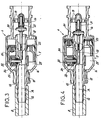
- the hydraulic connector 4 has a tubular main body 14, upstream of which the nut 6 is mounted, the main body 14 being extended downstream by a coaxial tubular part 15, on which is carried out the crimping 12 of the pipe 8.
- the overflow safety device 7 has a cylindrical casing 16, crimped on the main body 14 and providing, on the downstream side, at least one axial passage 17 between itself and the part tubular 15 of the body 14. The upstream end of the sheath 9 is fixed by the collar 10 around the downstream part of the casing 16.
- the tubular part 15 of the body 14 serves as a sliding guide for a rod 18, axially movable and also passing through a guide 19 located further back.
- the movable rod 18 carries a shutter 20, capable of coming against the upstream end of the tubular part 15.
- This tubular part 15 is crossed by a movable radial pin 22, with the interposition of a seal 23.
- the pin 22 has a spring 24 which tends to move it away from the axis of the connector 4.
- annular piston 25 Between the tubular part 15 and the cylindrical casing 16 is mounted an annular piston 25, to which is fixed on the downstream side a hollow cylinder 26.
- the assembly formed by the piston 25 and by the cylinder 26 is axially movable inside the casing 16. Due to passage 17, the pressure in the annular chamber 27 located in front of the piston 25 is equal to the pressure prevailing in the annular space 28 between the inner pipe 8 and the outer sheath 9 of the hose 3.
- An overflow safety device 7 is thus produced which, as a whole, is arranged along the axis A of the hydraulic connector 4, therefore which is coaxial with the passage of water through this connector 4 towards the pipe 8.
- the safety 7 authorizes the passage of water through the tubular part 15 of the connector 4.
- the piston 25 occupies its most downstream position, in which the cylinder 26 covers the head of the pin 22, to keep this pin 22 close to the axis A.
- the pin 22 then stops itself the downstream end of the movable rod 18, so that the shutter 20 remains spaced from the upstream end of the tubular part 15, the spring 21 being compressed as well as spring 24.
- the casing 16 of the safety device 7 is transparent, in whole or in part, it is easy to visualize the change in position of the piston 25, in particular if the latter is brightly colored.
- the casing 16 has a mark or an index, which makes it possible to give a meaning to the position of the piston 25 and to indicate that there is a defect.
Landscapes
- Engineering & Computer Science (AREA)
- Textile Engineering (AREA)
- Fire-Extinguishing By Fire Departments, And Fire-Extinguishing Equipment And Control Thereof (AREA)
- Quick-Acting Or Multi-Walled Pipe Joints (AREA)
- Actuator (AREA)
- Safety Valves (AREA)
- Pipe Accessories (AREA)
Applications Claiming Priority (2)
| Application Number | Priority Date | Filing Date | Title |
|---|---|---|---|
| FR9011046 | 1990-08-23 | ||
| FR9011046A FR2666135B1 (fr) | 1990-08-23 | 1990-08-23 | Dispositif de securite de debordement pour raccord hydraulique. |
Publications (2)
| Publication Number | Publication Date |
|---|---|
| EP0474569A1 true EP0474569A1 (de) | 1992-03-11 |
| EP0474569B1 EP0474569B1 (de) | 1995-09-20 |
Family
ID=9400109
Family Applications (1)
| Application Number | Title | Priority Date | Filing Date |
|---|---|---|---|
| EP91420302A Expired - Lifetime EP0474569B1 (de) | 1990-08-23 | 1991-08-21 | Sicherheitsvorrichtung gegen Überlauf bei einer hydraulischen Verbindung |
Country Status (5)
| Country | Link |
|---|---|
| EP (1) | EP0474569B1 (de) |
| DE (1) | DE69113189T2 (de) |
| ES (1) | ES2079617T3 (de) |
| FR (1) | FR2666135B1 (de) |
| YU (1) | YU138491A (de) |
Cited By (8)
| Publication number | Priority date | Publication date | Assignee | Title |
|---|---|---|---|---|
| EP0609842A1 (de) * | 1993-02-03 | 1994-08-10 | RE-FLEX S.r.l. | Lecksicherungsvorrichtung für Wasseranschlussleitungen an elektrischen Haushaltsmaschinen |
| WO2003014457A1 (en) * | 2001-08-08 | 2003-02-20 | Pietro Viola | Dishwashers and like |
| US6546951B1 (en) * | 2000-06-05 | 2003-04-15 | John G. Armenia | Appliance safety hose |
| EP1312849A3 (de) * | 2001-11-19 | 2003-06-04 | RE-FLEX S.r.l. | Rohr für die Verbindung von Wasch- und Spülmaschinen zum Wasserversorgungssystem |
| ITTO20110337A1 (it) * | 2011-04-15 | 2012-10-16 | Eltek Spa | Dispositivo di sicurezza contro perdite di fluido per elettrodomestici |
| ITTO20110338A1 (it) * | 2011-04-15 | 2012-10-16 | Eltek Spa | Dispositivo di sicurezza contro perdite di fluido per elettrodomestici |
| KR20140048112A (ko) * | 2011-04-15 | 2014-04-23 | 엘텍 에스.피.에이. | 가정용 기기, 특히 세척기용 넘침-방지 안전 장치 |
| EP2489298B1 (de) | 2011-02-18 | 2015-03-25 | BITRON S.p.A. | Vormontierte Anordnung für Wasserstoppvorrichtung und Vorrichtung damit |
Families Citing this family (3)
| Publication number | Priority date | Publication date | Assignee | Title |
|---|---|---|---|---|
| WO2014195014A2 (de) | 2013-06-07 | 2014-12-11 | Kottmann Technology Gmbh | Vorrichtung zur zuführung von flüssigkeit zu einem haushaltsgerät |
| DE102016001940A1 (de) | 2015-02-20 | 2016-08-25 | Kottmann Technology Gmbh | Vorrichtung zur Unterbindung und/oder Freigabe eines Fluidstroms |
| CN113445253B (zh) * | 2020-03-26 | 2022-12-09 | 青岛海尔洗衣机有限公司 | 洗涤设备及其控制方法 |
Citations (5)
| Publication number | Priority date | Publication date | Assignee | Title |
|---|---|---|---|---|
| DE2349237A1 (de) * | 1972-10-06 | 1974-04-18 | Elbi Spa | Vorrichtung mit elektromagnetischer steuerung zur ueberwachung des wasserstandes bei waschmaschinen |
| DE2928529A1 (de) * | 1979-07-14 | 1981-01-15 | Koch & Mueller Armaturenfab | Selbstschlussventil fuer gas- und wasserleitungen |
| DE2940215A1 (de) * | 1978-04-19 | 1981-04-16 | Gerd 5204 Lohmar Höffgen | Schlauchvorrichtung |
| DE3516795A1 (de) * | 1985-05-09 | 1986-11-13 | Wolfgang 8011 Baldham Dahmen | Schlauchbruchsicherungsvorrichtung |
| FR2596130A1 (fr) * | 1986-03-18 | 1987-09-25 | Socado | Dispositif de securite pour conduit flexible d'alimentation en eau pour appareils electromenagers |
-
1990
- 1990-08-23 FR FR9011046A patent/FR2666135B1/fr not_active Expired - Fee Related
-
1991
- 1991-08-12 YU YU138491A patent/YU138491A/sh unknown
- 1991-08-21 DE DE69113189T patent/DE69113189T2/de not_active Expired - Fee Related
- 1991-08-21 EP EP91420302A patent/EP0474569B1/de not_active Expired - Lifetime
- 1991-08-21 ES ES91420302T patent/ES2079617T3/es not_active Expired - Lifetime
Patent Citations (5)
| Publication number | Priority date | Publication date | Assignee | Title |
|---|---|---|---|---|
| DE2349237A1 (de) * | 1972-10-06 | 1974-04-18 | Elbi Spa | Vorrichtung mit elektromagnetischer steuerung zur ueberwachung des wasserstandes bei waschmaschinen |
| DE2940215A1 (de) * | 1978-04-19 | 1981-04-16 | Gerd 5204 Lohmar Höffgen | Schlauchvorrichtung |
| DE2928529A1 (de) * | 1979-07-14 | 1981-01-15 | Koch & Mueller Armaturenfab | Selbstschlussventil fuer gas- und wasserleitungen |
| DE3516795A1 (de) * | 1985-05-09 | 1986-11-13 | Wolfgang 8011 Baldham Dahmen | Schlauchbruchsicherungsvorrichtung |
| FR2596130A1 (fr) * | 1986-03-18 | 1987-09-25 | Socado | Dispositif de securite pour conduit flexible d'alimentation en eau pour appareils electromenagers |
Cited By (21)
| Publication number | Priority date | Publication date | Assignee | Title |
|---|---|---|---|---|
| EP0609842A1 (de) * | 1993-02-03 | 1994-08-10 | RE-FLEX S.r.l. | Lecksicherungsvorrichtung für Wasseranschlussleitungen an elektrischen Haushaltsmaschinen |
| US6546951B1 (en) * | 2000-06-05 | 2003-04-15 | John G. Armenia | Appliance safety hose |
| WO2003014457A1 (en) * | 2001-08-08 | 2003-02-20 | Pietro Viola | Dishwashers and like |
| EP1312849A3 (de) * | 2001-11-19 | 2003-06-04 | RE-FLEX S.r.l. | Rohr für die Verbindung von Wasch- und Spülmaschinen zum Wasserversorgungssystem |
| EP2489298B1 (de) | 2011-02-18 | 2015-03-25 | BITRON S.p.A. | Vormontierte Anordnung für Wasserstoppvorrichtung und Vorrichtung damit |
| CN103764895A (zh) * | 2011-04-15 | 2014-04-30 | 埃尔特克有限公司 | 用于家用器具的针对流体泄漏的安全装置 |
| KR20140053884A (ko) * | 2011-04-15 | 2014-05-08 | 엘텍 에스.피.에이. | 가전 제품의 유체 유출에 대한 안전 장치 |
| WO2012140595A3 (en) * | 2011-04-15 | 2013-11-07 | Eltek S.P.A. | Safety device against fluid leaks for household appliances |
| KR20140036184A (ko) * | 2011-04-15 | 2014-03-25 | 엘텍 에스.피.에이. | 가전 제품의 유체 유출에 대한 안전 장치 |
| KR20140048112A (ko) * | 2011-04-15 | 2014-04-23 | 엘텍 에스.피.에이. | 가정용 기기, 특히 세척기용 넘침-방지 안전 장치 |
| ITTO20110338A1 (it) * | 2011-04-15 | 2012-10-16 | Eltek Spa | Dispositivo di sicurezza contro perdite di fluido per elettrodomestici |
| CN103781393A (zh) * | 2011-04-15 | 2014-05-07 | 埃尔特克有限公司 | 用于家用器具的针对流体泄漏的安全装置 |
| WO2012140592A3 (en) * | 2011-04-15 | 2013-01-31 | Eltek S.P.A. | Safety device against fluid leaks for household appliances |
| US20140158226A1 (en) * | 2011-04-15 | 2014-06-12 | Eltek, S.P.A. | Anti-flooding safety device for household appliances, in particular washing machines |
| ITTO20110337A1 (it) * | 2011-04-15 | 2012-10-16 | Eltek Spa | Dispositivo di sicurezza contro perdite di fluido per elettrodomestici |
| RU2582951C2 (ru) * | 2011-04-15 | 2016-04-27 | Элтек С.П.А. | Устройство защиты от протечек текучей среды для бытовых приборов |
| RU2582953C2 (ru) * | 2011-04-15 | 2016-04-27 | Элтек С.П.А. | Устройство защиты от протечек текучей среды для бытовых приборов |
| US9464725B2 (en) * | 2011-04-15 | 2016-10-11 | Eltek S.P.A. | Anti-flooding safety device for household appliances, in particular washing machines |
| CN103781393B (zh) * | 2011-04-15 | 2016-10-19 | 埃尔特克有限公司 | 用于家用器具的针对流体泄漏的安全装置 |
| US9568115B2 (en) | 2011-04-15 | 2017-02-14 | Eltek S.P.A. | Safety device against fluid leaks for household appliances |
| EP2696739B1 (de) | 2011-04-15 | 2019-03-27 | Eltek S.p.A. | Leckschutzvorrichtung für haushaltsgeräte |
Also Published As
| Publication number | Publication date |
|---|---|
| FR2666135A1 (fr) | 1992-02-28 |
| ES2079617T3 (es) | 1996-01-16 |
| FR2666135B1 (fr) | 1993-06-11 |
| DE69113189T2 (de) | 1996-05-09 |
| YU138491A (sh) | 1994-11-15 |
| EP0474569B1 (de) | 1995-09-20 |
| DE69113189D1 (de) | 1995-10-26 |
Similar Documents
| Publication | Publication Date | Title |
|---|---|---|
| EP0474569B1 (de) | Sicherheitsvorrichtung gegen Überlauf bei einer hydraulischen Verbindung | |
| EP0540800A1 (de) | Handstück mit Düse zur Körperpflege | |
| EP0069612B1 (de) | Pumpenregelung durch Ansaugdrosselung mit einbezogener Druckbegrenzung | |
| FR2589552A2 (fr) | Dispositif de securite contre les inondations, pour appareils menagers utilisateurs d'eau | |
| EP0807946B1 (de) | Hochspannungs-Blaskolbenschalter | |
| FR2663715A1 (fr) | Dispositif de neutralisation d'une soupape de pression residuelle d'une bouteille a gaz. | |
| LU81751A1 (fr) | Dispositif de commande d'ecoulement pour robinet | |
| FR2596844A1 (fr) | Electrovanne comprenant des thermistances associees a un dispositif a dilatation de cire | |
| EP0051517B1 (de) | Elektromagnetisches Ventil | |
| EP1468147B1 (de) | Brauseschlauch mit einem zweiwegeventil und zweiwegenventil für brauseschlauch | |
| FR2659074A1 (fr) | Dispositif de soutirage et de rincage pour le debit de biere. | |
| EP2655946B1 (de) | Vorrichtung zur steuerung der flussrate eines kühlmittels | |
| WO2007104846A2 (fr) | Appareil de repassage comportant une cuve pour la production de vapeur sous pression | |
| FR2550619A1 (fr) | Soupape de remplissage et/ou de vidange d'un radiateur | |
| FR2527736A1 (fr) | Vanne magnetique | |
| FR2500957A1 (fr) | Mecanisme pour declencheur de courant de fuite combine avec un disjoncteur de protection de lignes | |
| FR2572487A1 (fr) | Robinet a dispositif antiretour pour le remplissage d'une enceinte fermee | |
| BE776581A (fr) | Robinet a fluxmetre | |
| FR2971426A1 (fr) | Exctincteur a pression permanente | |
| BE539401A (de) | ||
| FR2485876A3 (fr) | Embout pour abreuvoir | |
| EP0237407B1 (de) | Hahn mit einem eingebauten Absperrhahn | |
| EP0208632A1 (de) | Handgetriebene ferngesteuerte Ölablassvorrichtung | |
| EP1996759A2 (de) | Bügelvorrichtung, die einen behälter zum erzeugen von unter druck stehendem dampf umfasst | |
| FR2675374A1 (fr) | Dispositif d'assistance aidant une personne a se lever. |
Legal Events
| Date | Code | Title | Description |
|---|---|---|---|
| PUAI | Public reference made under article 153(3) epc to a published international application that has entered the european phase |
Free format text: ORIGINAL CODE: 0009012 |
|
| AK | Designated contracting states |
Kind code of ref document: A1 Designated state(s): DE ES GB IT |
|
| 17P | Request for examination filed |
Effective date: 19920718 |
|
| 17Q | First examination report despatched |
Effective date: 19940406 |
|
| GRAA | (expected) grant |
Free format text: ORIGINAL CODE: 0009210 |
|
| AK | Designated contracting states |
Kind code of ref document: B1 Designated state(s): DE ES GB IT |
|
| REF | Corresponds to: |
Ref document number: 69113189 Country of ref document: DE Date of ref document: 19951026 |
|
| ITF | It: translation for a ep patent filed | ||
| REG | Reference to a national code |
Ref country code: ES Ref legal event code: FG2A Ref document number: 2079617 Country of ref document: ES Kind code of ref document: T3 |
|
| GBT | Gb: translation of ep patent filed (gb section 77(6)(a)/1977) |
Effective date: 19951215 |
|
| PLBE | No opposition filed within time limit |
Free format text: ORIGINAL CODE: 0009261 |
|
| STAA | Information on the status of an ep patent application or granted ep patent |
Free format text: STATUS: NO OPPOSITION FILED WITHIN TIME LIMIT |
|
| 26N | No opposition filed | ||
| PGFP | Annual fee paid to national office [announced via postgrant information from national office to epo] |
Ref country code: ES Payment date: 19980820 Year of fee payment: 8 |
|
| PG25 | Lapsed in a contracting state [announced via postgrant information from national office to epo] |
Ref country code: ES Free format text: LAPSE BECAUSE OF NON-PAYMENT OF DUE FEES Effective date: 19990822 |
|
| REG | Reference to a national code |
Ref country code: GB Ref legal event code: IF02 |
|
| REG | Reference to a national code |
Ref country code: ES Ref legal event code: FD2A Effective date: 20000911 |
|
| PGFP | Annual fee paid to national office [announced via postgrant information from national office to epo] |
Ref country code: DE Payment date: 20070831 Year of fee payment: 17 |
|
| PGFP | Annual fee paid to national office [announced via postgrant information from national office to epo] |
Ref country code: GB Payment date: 20070705 Year of fee payment: 17 |
|
| PGFP | Annual fee paid to national office [announced via postgrant information from national office to epo] |
Ref country code: IT Payment date: 20070814 Year of fee payment: 17 |
|
| GBPC | Gb: european patent ceased through non-payment of renewal fee |
Effective date: 20080821 |
|
| PG25 | Lapsed in a contracting state [announced via postgrant information from national office to epo] |
Ref country code: IT Free format text: LAPSE BECAUSE OF NON-PAYMENT OF DUE FEES Effective date: 20080821 Ref country code: DE Free format text: LAPSE BECAUSE OF NON-PAYMENT OF DUE FEES Effective date: 20090303 |
|
| PG25 | Lapsed in a contracting state [announced via postgrant information from national office to epo] |
Ref country code: GB Free format text: LAPSE BECAUSE OF NON-PAYMENT OF DUE FEES Effective date: 20080821 |