EP0474569B1 - Sicherheitsvorrichtung gegen Überlauf bei einer hydraulischen Verbindung - Google Patents
Sicherheitsvorrichtung gegen Überlauf bei einer hydraulischen Verbindung Download PDFInfo
- Publication number
- EP0474569B1 EP0474569B1 EP91420302A EP91420302A EP0474569B1 EP 0474569 B1 EP0474569 B1 EP 0474569B1 EP 91420302 A EP91420302 A EP 91420302A EP 91420302 A EP91420302 A EP 91420302A EP 0474569 B1 EP0474569 B1 EP 0474569B1
- Authority
- EP
- European Patent Office
- Prior art keywords
- piston
- connection
- safety device
- pin
- water
- Prior art date
- Legal status (The legal status is an assumption and is not a legal conclusion. Google has not performed a legal analysis and makes no representation as to the accuracy of the status listed.)
- Expired - Lifetime
Links
- XLYOFNOQVPJJNP-UHFFFAOYSA-N water Substances O XLYOFNOQVPJJNP-UHFFFAOYSA-N 0.000 claims description 51
- 238000011144 upstream manufacturing Methods 0.000 claims description 14
- 230000000694 effects Effects 0.000 claims description 7
- 238000005406 washing Methods 0.000 claims description 5
- 238000007789 sealing Methods 0.000 claims description 2
- 230000008878 coupling Effects 0.000 description 2
- 238000010168 coupling process Methods 0.000 description 2
- 238000005859 coupling reaction Methods 0.000 description 2
- 239000002184 metal Substances 0.000 description 2
- 241000206607 Porphyra umbilicalis Species 0.000 description 1
- 240000008042 Zea mays Species 0.000 description 1
- 238000002788 crimping Methods 0.000 description 1
- 230000007547 defect Effects 0.000 description 1
- 238000004851 dishwashing Methods 0.000 description 1
- 239000007788 liquid Substances 0.000 description 1
- 239000012528 membrane Substances 0.000 description 1
- 230000011664 signaling Effects 0.000 description 1
- 238000004804 winding Methods 0.000 description 1
Images
Classifications
-
- D—TEXTILES; PAPER
- D06—TREATMENT OF TEXTILES OR THE LIKE; LAUNDERING; FLEXIBLE MATERIALS NOT OTHERWISE PROVIDED FOR
- D06F—LAUNDERING, DRYING, IRONING, PRESSING OR FOLDING TEXTILE ARTICLES
- D06F39/00—Details of washing machines not specific to a single type of machines covered by groups D06F9/00 - D06F27/00
- D06F39/08—Liquid supply or discharge arrangements
- D06F39/081—Safety arrangements for preventing water damage
Definitions
- the present invention relates to an overflow safety device for a hydraulic connection of a water supply hose to a washing machine or dish, or other similar device, the safety device having the role of limiting the damage caused by water leaks, in the event of a rupture of the interior hose of the flexible hose, which includes an interior hose and an exterior waterproof sheath.
- the general known principle of such a safety device resides in the fact that, in the event of a leak, the pressurized water enters the annular space delimited by the inner pipe and the outer sheath of the hose, and this water can then reach the hydraulic connection to activate a valve, incorporated in this connection, which then closes the passage of water through said connection.
- Permanent magnet devices have a rubber membrane which, under the action of water pressure, moves a magnet. This movement has the effect of loosening a metal core which comes to close the passage of water.
- An exemplary embodiment is provided by document FR-A-2202286 (ELBI).
- the temperature variations modify the magnetic characteristics, according to a physical phenomenon well known for magnets in general.
- the use of more or less hot water to supply washing machines changes the strength of the magnet, and variations in the ambient temperature have the same disturbing effect.
- the design of the device must take this fact into account by oversizing the magnet, increasing costs, otherwise under the action of the temperature the magnet risk of loosening the metal core so that the valve closes the water passage when there is no real fault requiring this closure.
- the valve for closing the water passage is usually arranged along an axis perpendicular to the general axis of the hydraulic connection.
- SOCADO SOCR-A-2596130
- the safety device is arranged in a cylindrical casing coaxial with the hydraulic connection, and it comprises a piston mounted movable in the direction of the axis of the connection inside the cylindrical casing, the piston being subjected to the pressure of possible leaks in the water passage of the fitting is axially movable mounted a rod which carries a shutter, the piston being able to occupy a normal position in which it maintains the water passage and another position causing the closure of the water passage by actuation of the movable rod and the shutter.
- the piston has the usual shape of a disc, and therefore the water passage is located on the side of the piston, so that the arrangement is not entirely coaxial.
- This piston is integral with the movable rod carrying the shutter, and a spring acts on the piston in the direction of opening of the shutter.
- the present invention avoids the drawbacks of permanent magnet devices, sensitive to temperature and costly, as well as those of current purely mechanical devices, by providing a device of the mechanical type but of a reduced bulk and improved functioning and aesthetics.
- the invention essentially relates to an overflow safety device for hydraulic connection, of the type indicated in the preamble of claim 1, in which the piston is an annular piston mounted coaxially with a tubular part defining the passage. of water from the fitting, and the shutter cooperates with the upstream end of the tubular part and is subjected, with the movable rod, to the effect of a spring tending to bring it closer to this upstream end, while a radially movable pin cooperates on the one hand with the movable rod carrying the shutter and on the other hand with an element linked to the annular piston, so that, in the normal position of the piston, the aforementioned element keeps the pin close to the axis of the fitting, in a position where the movable rod stops holding the shutter away from the downstream end of the tubular part, while in the other position of the piston, the aforementioned element releases the g oupille which itself releases the movable rod, so that the shutter is moved by the spring to a closed position for the passage of water.
- the piston
- the pin also comprises a spring, which is compressed during the initial assembly of the device and tends to move this pin radially away from the axis of the fitting, when it is released by the element linked to the annular piston.
- This element may consist of a hollow cylinder, integral with the annular piston and sliding with the latter in the cylindrical casing.
- the radially movable pin can in particular cooperate with the downstream end of the axially movable rod, in order to normally keep the shutter spaced from the upstream end of the tubular part closing the passage of water.
- the cylindrical casing is made at least partially transparent, to visualize the passage of the annular piston from its normal position to its other position causing the closure of the water passage.
- the safety device thus comprises signaling means, allowing the user to be warned of the triggering of the device and of the existence of a leak having caused this triggering.
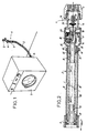
- the invention relates to the supply of water to a household appliance 1 such as a washing machine, from a water inlet tap 2 of a distribution network of water.
- the tap 2 is connected to the machine 1 by a hose 3, which has at its upstream end a hydraulic connection 4 for its connection to the outlet of the tap 2, and at its downstream end a coupling 5 for coupling to a solenoid valve. inlet of the machine 1.
- the hydraulic connection 4 mainly consists of a nut 6 for connection to the valve 2, and an overflow safety device 7, more particularly the subject of the present invention.
- the hose 3 comprises an inner pipe 8 through which the water is to be brought to the machine 1, and an outer sealed sheath 9 provided, at its ends, with fixing and sealing collars 10 and 11, associated respectively with fittings 4 and 5.
- the function of the safety device 7 is to interrupt the arrival of water, if a water leak occurs inside the tight sheath 9, in coming from the inner pipe 8 or the crimps 12 and 13 of this pipe respectively on the fittings 4 and 5.
- the hydraulic connector 4 has a tubular main body 14, upstream of which the nut 6 is mounted, the main body 14 being extended downstream by a coaxial tubular part 15, on which is carried out the crimping 12 of the pipe 8.
- the overflow safety device 7 has a cylindrical casing 16, crimped on the main body 14 and providing, on the downstream side, at least one axial passage 17 between itself and the part tubular 15 of the body 14. The upstream end of the sheath 9 is fixed by the collar 10 around the downstream part of the casing 16.
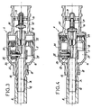
- the tubular part 15 of the body 14 serves as a sliding guide for a rod 18, axially movable and also passing through a guide 19 located further back.
- the movable rod 18 carries a shutter 20, capable of coming against the upstream end of the tubular part 15.
- This tubular part 15 is crossed by a movable radial pin 22, with the interposition of a seal 23.
- the pin 22 has a spring 24 which tends to move it away from the axis of the connector 4.
- annular piston 25 Between the tubular part 15 and the cylindrical casing 16 is mounted an annular piston 25, to which is fixed on the downstream side a hollow cylinder 26.
- the assembly formed by the piston 25 and by the cylinder 26 is axially movable inside the casing 16. Due to passage 17, the pressure in the annular chamber 27 located in front of the piston 25 is equal to the pressure prevailing in the annular space 28 between the inner pipe 8 and the outer sheath 9 of the hose 3.
- An overflow safety device 7 is thus produced which, as a whole, is arranged along the axis A of the hydraulic connector 4, therefore which is coaxial with the passage of water through this connector 4 towards the pipe 8.
- the safety 7 allows the passage of water through the tubular part 15 of the connector 4.
- the piston 25 occupies its most downstream position, in which the cylinder 26 covers the head of the pin 22, to keep this pin 22 close to the axis A.
- the pin 22 then stops itself the downstream end of the movable rod 18, so that the shutter 20 remains spaced from the upstream end of the tubular part 15, the spring 21 being compressed as well as spring 24.
- the casing 16 of the safety device 7 is transparent, in whole or in part, it is easy to visualize the change in position of the piston 25, in particular if the latter is brightly colored.
- the casing 16 has a mark or an index, which makes it possible to give a meaning to the position of the piston 25 and to indicate that there is a defect.
Landscapes
- Engineering & Computer Science (AREA)
- Textile Engineering (AREA)
- Fire-Extinguishing By Fire Departments, And Fire-Extinguishing Equipment And Control Thereof (AREA)
- Quick-Acting Or Multi-Walled Pipe Joints (AREA)
- Actuator (AREA)
- Safety Valves (AREA)
- Pipe Accessories (AREA)
Claims (6)
- Sicherheitsvorrichtung gegen Leckagen für einen hydraulischen Anschluß (4), wobei über einen Schlauch (3) Wasser einer Waschmaschine, Geschirrspülmaschine oder ähnlichen Maschine zugeführt wird, wobei der Schlauch (3) ein Innenrohr (8) und eine äußere, dichte Umhüllung (9) aufweist, wobei ferner ein Ringraum (28) vorgesehen ist, der einerseits vom Innenrohr (8) und andererseits von der äußeren Umhüllung (9) begrenzt wird, wobei bei einem Leck das Wasser unter Druck in den Ringraum (28) eindringen kann und das Wasser den hydraulischen Anschluß (4) erreichen kann, um ein Ventil (18 - 21) zu betätigen, das in den Anschluß (4) eingebaut ist, das jetzt einen Wasserdurchtritt (15) des Anschlusses verschließt, wobei die Sicherheitsvorrichtung (7) in einem koaxialen, zylindrischen Gehäuse (16) des hydraulischen Anschlusses (4) vorgesehen ist und einen Kolben (25) aufweist, der in Richtung der Achse (A) des Anschlusses (4) im Inneren des zylindrischen Gehäuses (16) beweglich ist, und wobei der Kolben dem Druck eventueller Leckagen unterliegt, während in dem Wasserdurchtritt (15) des Anschlusses eine Stange (18) beweglich montiert ist, die ein Verschlußstück (20) trägt und der Kolben eine normale Lage einnehmen kann, in der er den Wasserdurchtritt (15) aufrechterhält, sowie eine weitere Position, in der der Wasserdurchtritt durch Betätigung der beweglichen Stange (18) und des Verschlußstückes (20) verschlossen wird,
dadurch gekennzeichnet,
daß der Kolben als Ringkolben (25) ausgebildet ist, der koaxial an einem Rohrstück (15) montiert ist, das den Wasserdurchtritt des Anschlusses (4) definiert, und daß das Verschlußstück (20) mit dem stromauf gelegenen Ende des Rohrstücks (15) zusammenarbeitet und, zusammen mit der beweglichen Stange (18), der Wirkung einer Feder (21) unterliegt, die dieses stromauf gelegene Ende daran anzunähern sucht, während ein radial beweglicher Stift (22) mit einem Teil der beweglichen Stange (18) zusammenarbeitet, die das Verschlußstück (20) trägt und andererseit mit einem Element (26), das mit dem ringförmigen Kolben (25) derart verbunden ist, daß in der Normallage des Kolbens das vorstehend erwähnte Element (26) den Stift (22) angenähert an die Achse (A) des Anschlusses (4) hält, und zwar in einer Halteposition für die bewegliche Stange (18), wobei das Verschlußstück (20) beabstandet von dem stromauf gelegenen Ende des rohrförmigen Teils (15) gehalten wird, während in der anderen Lage des Kolbens (25) das vorstehend erwähnte Element (26) den Stift (22) freigibt, der seinerseits die bewegliche Stange (18) freigibt derart, daß das Verschlußstück (20) von der Feder (21) in eine Schließlage für den Wasserdurchtritt (15) verschoben wird. - Sicherheitsvorrichtung nach Anspruch 1,
dadurch gekennzeichnet,
daß der Stift (22) eine Feder (24) aufweist, die bei der anfänglichen Montage der Vorrichtung (7) komprimiert wird, die den Stift (22) radial zu verschieben sucht, indem der Stift von der Achse (A) des Anschlusses (4) hinweggeschoben wird, und zwar im Augenblick der Freisetzung des Elements (26), das mit dem Ringkolben (25) verbunden ist. - Sicherheitsvorrichtung nach Anspruch 1 oder 2,
dadurch gekennzeichnet,
daß das Element, das mit dem Ringkolben (25) verbunden ist, und das mit dem Stift (22) zusammenarbeitet, als Hohlzylinder (26) ausgebildet ist, der mit dem Ringkolben (25) fest verbunden ist, und der mit dem Ringkolben im zylindrischen Gehäuse (16) gleitet. - Sicherheitsvorrichtung nach einem der Ansprüche 1 bis 3,
dadurch gekennzeichnet,
daß der radial verschiebbare Stift (22) mit dem stromab gelegenen Ende der radial beweglichen Stange (18) zusammenarbeitet, um das Verschlußteil (20) normalerweise vom stromauf gelegenen Ende des Rohrstücks (15) beabstandet zu halten, das den Wasserdurchtritt verschließt. - Sicherheitsvorrichtung nach einem der Ansprüche 1 bis 4,
dadurch gekennzeichnet,
daß das Rohrstück (15) radial vom Stift (22) durchquert wird, wobei eine Abdichtung (23) dazwischen vorgesehen ist, wobei die Anordnung derart getroffen ist, daß bei einer Leckage im Gebiet der Abdichtung (23) das aus dem Rohrstück (15) austretende Druckwasser bis zum Ringkolben (25) kommt, diesen verschiebt und somit den Wasserdurchtritt (15) im Anschluß (4) verschließt. - Sicherheitsvorrichtung nach einem der Ansprüche 1 bis 5,
dadurch gekennzeichnet,
daß das zylindrische Gehäuse (16) wenigtens teileweise durchsichtig ist, so daß die Verschiebung des Ringkolbens (25) aus seiner Normallage in seine andere Lage sichtbar ist, in der der Wasserdurchtritt (15) verschlossen ist.
Applications Claiming Priority (2)
| Application Number | Priority Date | Filing Date | Title |
|---|---|---|---|
| FR9011046 | 1990-08-23 | ||
| FR9011046A FR2666135B1 (fr) | 1990-08-23 | 1990-08-23 | Dispositif de securite de debordement pour raccord hydraulique. |
Publications (2)
| Publication Number | Publication Date |
|---|---|
| EP0474569A1 EP0474569A1 (de) | 1992-03-11 |
| EP0474569B1 true EP0474569B1 (de) | 1995-09-20 |
Family
ID=9400109
Family Applications (1)
| Application Number | Title | Priority Date | Filing Date |
|---|---|---|---|
| EP91420302A Expired - Lifetime EP0474569B1 (de) | 1990-08-23 | 1991-08-21 | Sicherheitsvorrichtung gegen Überlauf bei einer hydraulischen Verbindung |
Country Status (5)
| Country | Link |
|---|---|
| EP (1) | EP0474569B1 (de) |
| DE (1) | DE69113189T2 (de) |
| ES (1) | ES2079617T3 (de) |
| FR (1) | FR2666135B1 (de) |
| YU (1) | YU138491A (de) |
Cited By (1)
| Publication number | Priority date | Publication date | Assignee | Title |
|---|---|---|---|---|
| WO2021190202A1 (zh) * | 2020-03-26 | 2021-09-30 | 青岛海尔洗衣机有限公司 | 洗涤设备及其控制方法 |
Families Citing this family (10)
| Publication number | Priority date | Publication date | Assignee | Title |
|---|---|---|---|---|
| IT1268506B1 (it) * | 1993-02-03 | 1997-03-04 | Re Flex Srl | Dispositivo antiallagamento per tubi d'alimentazione d'acqua di apparecchi elettrodomestici |
| US6546951B1 (en) * | 2000-06-05 | 2003-04-15 | John G. Armenia | Appliance safety hose |
| WO2003014457A1 (en) * | 2001-08-08 | 2003-02-20 | Pietro Viola | Dishwashers and like |
| ITMI20010611U1 (it) * | 2001-11-19 | 2003-05-19 | Re Flex Srl | Tubo per la connessione alla rete idrica di lavatrici e lavastoviglie |
| IT1406070B1 (it) | 2011-02-18 | 2014-02-06 | Bitron Spa | Gruppo pre-montato per dispositivo acquastop e dispositivo che lo comprende |
| ITTO20110035U1 (it) * | 2011-04-15 | 2012-10-16 | Eltek Spa | Dispositivo di sicurezza antiallagamento per elettrodomestici, in particolare macchine di lavaggio |
| ITTO20110338A1 (it) * | 2011-04-15 | 2012-10-16 | Eltek Spa | Dispositivo di sicurezza contro perdite di fluido per elettrodomestici |
| ITTO20110337A1 (it) * | 2011-04-15 | 2012-10-16 | Eltek Spa | Dispositivo di sicurezza contro perdite di fluido per elettrodomestici |
| WO2014195014A2 (de) | 2013-06-07 | 2014-12-11 | Kottmann Technology Gmbh | Vorrichtung zur zuführung von flüssigkeit zu einem haushaltsgerät |
| DE102016001940A1 (de) | 2015-02-20 | 2016-08-25 | Kottmann Technology Gmbh | Vorrichtung zur Unterbindung und/oder Freigabe eines Fluidstroms |
Family Cites Families (5)
| Publication number | Priority date | Publication date | Assignee | Title |
|---|---|---|---|---|
| DE2349237B2 (de) * | 1972-10-06 | 1980-05-29 | Elbi S.P.A., Regina Margheritacollegno, Turin (Italien) | Gerät zur Überlaufsicherung bei Waschmaschinen, Geschirrspülmaschinen u. dgl |
| DE2940215A1 (de) * | 1978-04-19 | 1981-04-16 | Gerd 5204 Lohmar Höffgen | Schlauchvorrichtung |
| DE2928529C2 (de) * | 1979-07-14 | 1984-01-05 | Armaturenfabrik und Metallgießerei Koch und Müller GmbH, 4250 Bottrop | Selbstschlußventil für Gas- und Wasserleitungen |
| DE3516795A1 (de) * | 1985-05-09 | 1986-11-13 | Wolfgang 8011 Baldham Dahmen | Schlauchbruchsicherungsvorrichtung |
| FR2596130B1 (fr) * | 1986-03-18 | 1989-03-03 | Socado | Dispositif de securite pour conduit flexible d'alimentation en eau pour appareils electromenagers |
-
1990
- 1990-08-23 FR FR9011046A patent/FR2666135B1/fr not_active Expired - Fee Related
-
1991
- 1991-08-12 YU YU138491A patent/YU138491A/sh unknown
- 1991-08-21 DE DE69113189T patent/DE69113189T2/de not_active Expired - Fee Related
- 1991-08-21 EP EP91420302A patent/EP0474569B1/de not_active Expired - Lifetime
- 1991-08-21 ES ES91420302T patent/ES2079617T3/es not_active Expired - Lifetime
Cited By (1)
| Publication number | Priority date | Publication date | Assignee | Title |
|---|---|---|---|---|
| WO2021190202A1 (zh) * | 2020-03-26 | 2021-09-30 | 青岛海尔洗衣机有限公司 | 洗涤设备及其控制方法 |
Also Published As
| Publication number | Publication date |
|---|---|
| FR2666135A1 (fr) | 1992-02-28 |
| ES2079617T3 (es) | 1996-01-16 |
| FR2666135B1 (fr) | 1993-06-11 |
| EP0474569A1 (de) | 1992-03-11 |
| DE69113189T2 (de) | 1996-05-09 |
| YU138491A (sh) | 1994-11-15 |
| DE69113189D1 (de) | 1995-10-26 |
Similar Documents
| Publication | Publication Date | Title |
|---|---|---|
| EP0474569B1 (de) | Sicherheitsvorrichtung gegen Überlauf bei einer hydraulischen Verbindung | |
| EP0976598A1 (de) | Rückschlagventil für Kraftstofftank | |
| EP0069612B1 (de) | Pumpenregelung durch Ansaugdrosselung mit einbezogener Druckbegrenzung | |
| CA2015663C (fr) | Robinet a tournant spherique | |
| FR2687448A1 (fr) | Soupape thermostatique de securite pour circuit de refroidissement hydraulique. | |
| EP0807946B1 (de) | Hochspannungs-Blaskolbenschalter | |
| FR2727787A1 (fr) | Interrupteur electrique de securite | |
| FR2663715A1 (fr) | Dispositif de neutralisation d'une soupape de pression residuelle d'une bouteille a gaz. | |
| FR2589552A2 (fr) | Dispositif de securite contre les inondations, pour appareils menagers utilisateurs d'eau | |
| EP0066795B1 (de) | Schnell schliessendes Ventil für komprimierbares Fluidum | |
| EP0051517B1 (de) | Elektromagnetisches Ventil | |
| CA1206064A (fr) | Obturateur destine a etre monte dans un corps | |
| WO2003062542A1 (fr) | Tuyau de douche ayant une vanne a deux voies, et vanne a deux voies pour un tuyau de douche | |
| FR2830600A1 (fr) | Groupe de soupapes de derivation en particulier pour une machine a laver et secher la vaisselle | |
| FR2514041A1 (fr) | Dispositif anti-debordement de securite pour machines a laver le linge et similaires | |
| FR2573783A1 (fr) | Dispositif d'injection d'eau pour fer a repasser a vapeur | |
| FR2599110A1 (fr) | Robinet equipe de clapets d'obturation et anti-retour | |
| FR2527736A1 (fr) | Vanne magnetique | |
| WO2007104846A2 (fr) | Appareil de repassage comportant une cuve pour la production de vapeur sous pression | |
| FR2646678A1 (fr) | Dispositif de regulation du niveau de l'eau dans un reservoir de chasse d'eau | |
| FR2572487A1 (fr) | Robinet a dispositif antiretour pour le remplissage d'une enceinte fermee | |
| BE539401A (de) | ||
| FR2719302A1 (fr) | Borne de distribution de fluide à carte électronique autorisant le puisage. | |
| EP0208632A1 (de) | Handgetriebene ferngesteuerte Ölablassvorrichtung | |
| FR2485876A3 (fr) | Embout pour abreuvoir |
Legal Events
| Date | Code | Title | Description |
|---|---|---|---|
| PUAI | Public reference made under article 153(3) epc to a published international application that has entered the european phase |
Free format text: ORIGINAL CODE: 0009012 |
|
| AK | Designated contracting states |
Kind code of ref document: A1 Designated state(s): DE ES GB IT |
|
| 17P | Request for examination filed |
Effective date: 19920718 |
|
| 17Q | First examination report despatched |
Effective date: 19940406 |
|
| GRAA | (expected) grant |
Free format text: ORIGINAL CODE: 0009210 |
|
| AK | Designated contracting states |
Kind code of ref document: B1 Designated state(s): DE ES GB IT |
|
| REF | Corresponds to: |
Ref document number: 69113189 Country of ref document: DE Date of ref document: 19951026 |
|
| ITF | It: translation for a ep patent filed | ||
| REG | Reference to a national code |
Ref country code: ES Ref legal event code: FG2A Ref document number: 2079617 Country of ref document: ES Kind code of ref document: T3 |
|
| GBT | Gb: translation of ep patent filed (gb section 77(6)(a)/1977) |
Effective date: 19951215 |
|
| PLBE | No opposition filed within time limit |
Free format text: ORIGINAL CODE: 0009261 |
|
| STAA | Information on the status of an ep patent application or granted ep patent |
Free format text: STATUS: NO OPPOSITION FILED WITHIN TIME LIMIT |
|
| 26N | No opposition filed | ||
| PGFP | Annual fee paid to national office [announced via postgrant information from national office to epo] |
Ref country code: ES Payment date: 19980820 Year of fee payment: 8 |
|
| PG25 | Lapsed in a contracting state [announced via postgrant information from national office to epo] |
Ref country code: ES Free format text: LAPSE BECAUSE OF NON-PAYMENT OF DUE FEES Effective date: 19990822 |
|
| REG | Reference to a national code |
Ref country code: GB Ref legal event code: IF02 |
|
| REG | Reference to a national code |
Ref country code: ES Ref legal event code: FD2A Effective date: 20000911 |
|
| PGFP | Annual fee paid to national office [announced via postgrant information from national office to epo] |
Ref country code: DE Payment date: 20070831 Year of fee payment: 17 |
|
| PGFP | Annual fee paid to national office [announced via postgrant information from national office to epo] |
Ref country code: GB Payment date: 20070705 Year of fee payment: 17 |
|
| PGFP | Annual fee paid to national office [announced via postgrant information from national office to epo] |
Ref country code: IT Payment date: 20070814 Year of fee payment: 17 |
|
| GBPC | Gb: european patent ceased through non-payment of renewal fee |
Effective date: 20080821 |
|
| PG25 | Lapsed in a contracting state [announced via postgrant information from national office to epo] |
Ref country code: IT Free format text: LAPSE BECAUSE OF NON-PAYMENT OF DUE FEES Effective date: 20080821 Ref country code: DE Free format text: LAPSE BECAUSE OF NON-PAYMENT OF DUE FEES Effective date: 20090303 |
|
| PG25 | Lapsed in a contracting state [announced via postgrant information from national office to epo] |
Ref country code: GB Free format text: LAPSE BECAUSE OF NON-PAYMENT OF DUE FEES Effective date: 20080821 |