EP0474541B1 - Verfahren und Vorrichtung zur Taktsignalregelung in einem Synchronsystem - Google Patents
Verfahren und Vorrichtung zur Taktsignalregelung in einem Synchronsystem Download PDFInfo
- Publication number
- EP0474541B1 EP0474541B1 EP91402322A EP91402322A EP0474541B1 EP 0474541 B1 EP0474541 B1 EP 0474541B1 EP 91402322 A EP91402322 A EP 91402322A EP 91402322 A EP91402322 A EP 91402322A EP 0474541 B1 EP0474541 B1 EP 0474541B1
- Authority
- EP
- European Patent Office
- Prior art keywords
- adjustment
- memory
- clock signals
- reading
- value
- Prior art date
- Legal status (The legal status is an assumption and is not a legal conclusion. Google has not performed a legal analysis and makes no representation as to the accuracy of the status listed.)
- Expired - Lifetime
Links
Images

Classifications
-
- G—PHYSICS
- G06—COMPUTING OR CALCULATING; COUNTING
- G06F—ELECTRIC DIGITAL DATA PROCESSING
- G06F1/00—Details not covered by groups G06F3/00 - G06F13/00 and G06F21/00
- G06F1/04—Generating or distributing clock signals or signals derived directly therefrom
- G06F1/08—Clock generators with changeable or programmable clock frequency
-
- G—PHYSICS
- G06—COMPUTING OR CALCULATING; COUNTING
- G06F—ELECTRIC DIGITAL DATA PROCESSING
- G06F1/00—Details not covered by groups G06F3/00 - G06F13/00 and G06F21/00
- G06F1/04—Generating or distributing clock signals or signals derived directly therefrom
- G06F1/10—Distribution of clock signals, e.g. skew
Definitions
- the invention applies to synchronous systems, such as example the central subsystem of a computer system.
- These systems are composed of a plurality of units functional, usually in the form of circuits integrated distributed on electronic cards and all these units (cards and / or integrated circuits) work in synchronism under the control of clock signals supplied from a common base clock.
- clock signals are generated by clock generators from a signal basic clock provided for example by an oscillator with quartz.
- the correction can therefore be made at the level of these generators by acting on the phase of the signals emitted and especially on their amplitude (in voltage or current) by adjusting the characteristics of the amplifiers generator output.
- the safest solution is to operate each system on a test bench and look for the fix which provides the coincidence in amplitude and phase between the signals actually obtained and reference signals. These reference signals define characteristics imposed by the system specifications we want achieve.
- the adjustments to be made are defined by a binary number defining the value of the settings. For make the correction according to the value of adjustment, delay circuits and discretely adjustable amplifiers.
- the means of maintenance generally provided in such a system have synchronous circuits, synchronized by the system clock to perform certain interventions at functional unit level in progress Operating.
- These synchronous circuits have usually read and write circuits as well that automata allowing for example to carry out dynamic dialogues with the units.
- the method according to the invention is carried out so that reading from said memory is performed by a read circuit synchronized by said clock signals, that reading said memory is accompanied by an existence detection read errors, so that, in the absence of an error, said adjustment means are controlled directly by the value read from said memory, so that, in the event error, said adjustment means are controlled by a modified value of said adjustment parameters and that the first reading of said memory is preceded by a step consisting in controlling said adjustment means by an approximate value of the adjustment parameters.
- Reading errors can be detected by various ways. We could for example use a encryption method or add to setting parameters a binary word of a particular profile whose non detection while reading would indicate an error of reading. Another solution is to use a code error detector associated with the data in memory and calculate the error syndrome after each reading. he then you have to modify the parameters of setting. If the reading error is only due to the setting imperfect initial, the choice of the modified value of these parameters can then be done by successive tests following: value corresponding to the most probable, then corresponding to an intermediate case between the most likely and the worst technology technology and then corresponding to an intermediate case between the most likely and the best technology technology, then to the case corresponding to the best technology, then the worst case technology. Of course, the previous tests are stopped when memory reading is performed without error.
- the method according to one embodiment of the invention is in further characterized in that said parameters being under binary numeric form, said optimal values are associated with an error detection code which is also loaded into said memory and in that after read memory, error detection operation is performed by means of said error detection code.
- the process according to an embodiment of the invention is further characterized in that said code is an error correcting code allowing at least correct a simple error and in that in case of detection of a simple error, said modified value is the value read and corrected using said code.
- the invention also relates to a synchronous system allowing the implementation of the process presented previously.
- Figure 1 shows schematically and as a example application the central subsystem of a computer system consisting of one or more cards CPU processor, one or more I / O cards IOU, SCU memory controller, MU memory cards and a CMU maintenance card. These units are associated with a service processor SP connected to the card CMU maintenance, itself connected to the other units by via a CMB maintenance bus.
- Each card for example one of the CPU processor cards, includes several functional units BDP, EAD, FPP, DIR, DAT can each be performed in the form of a integrated circuit. All units of all cards operate synchronously and communicate between them by appropriate functional links (bus by example) not shown. The functional units of each card are synchronized by a generator ARG clock signals mounted on the card and the operation is controlled by the service processor via the CMB bus.
- the CMU maintenance card has a clock generator primary or master (hereinafter referred to as ARG-M) who provides to secondary clock generators or slaves of other master clock signal cards by through specific links not shown.
- ARG-M clock generator primary or master
- the CMU card includes an MP microprocessor system associated with a RAM, a ROM read-only memory, a direct access unit to DMA memory and circuits interface (IP, IF) with the processor respectively SP service and the CMB bus.
- MP microprocessor system associated with a RAM, a ROM read-only memory, a direct access unit to DMA memory and circuits interface (IP, IF) with the processor respectively SP service and the CMB bus.
- the CMB bus is a conventional microprocessor bus with data, address and control lines whose detailed description is superfluous because known in the microprocessor technique.
- This bus is connected to the functional units as well as to the generators card clock to control operations maintenance at the system level and in particular at control initialization and adjustment of signals clock.
- the clock system works globally in the way next.
- the microprocessor mP runs specific firmware resulting in particular in placing on the CMB bus, via the IF interface, signals from command to the various clock generators ARG. Detailed operation at the level of each clock generator will be explained with reference to the figure 2.
- FIG. 2 shows the ARG-M clock generator as well than a non-volatile memory 1 of the maintenance card CMU.
- ARG-M generator circuits can be subdivided into three main parts: one part PM master, a PE slave part and a synchronous part PS.
- the PM master part which includes an oscillator with quartz (not shown) provides clock signals master PHP1, PHP2 intended for the various cards of the system numbered 0, 1, ..., p, the CMU card bearing the number zero.
- Clock generators of other units also have a synchronous part and a part slave receiving the master clock signals which their are destined. From the master clock signals PHP1, PHP2, each clock generator generates by through its slave part of the clock signals secondary or slaves CK1, CK2 for various integrated circuits of the card.
- the signals PHP1 (0), PHP2 (0) are sent to the PE slave part of the ARG-M generator of the CMU card. From these signals, PE supplies the slave clock signals CK1 (0), CK2 (0), ..., CK1 (i), CK2 (i), ..., CK1 (n), CK2 (n) intended respectively to the integrated circuits numbered 0, ..., i, ..., n of the card considered.
- the signals CK1 (0), CK2 (0) are transmitted to the synchronous part PS of the generator.
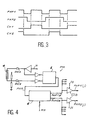
- the shape of the signals PHP1, PHP2, CK1, CK2 is represented in Figure 3.
- the PHP1 signal has a frequency double of each of the signals CK1 and CK2 while the signal PHP2 is a signal of discrimination of these two phases.
- This purely illustrative example is located in a context of a two-phase operation CK1, CK2, the master clock shown having been chosen for increase the phase tolerance of PHP1 and PHP2 signals taking into account the disturbances due to the connections between the master clock generator and clock generators slaves of the different cards.
- the CMB maintenance bus is connected to the synchronous part PS through IO interface circuits serving in particular to the resynchronization of the exchanged signals between the microprocessor mP and the synchronous part PS because the microprocessor system is synchronized by a clock independent of that of the system to be set.
- the ARG-M generator includes an RT adjustment register the output of which is connected to the adjustment inputs of the master and slave parts PM, PE so as to provide them the respective setting values.
- the setting register RT is commanded in writing by a selection circuit and Write 2 connected as an input to the CMB maintenance buses.
- the RT setting register input is connected to the output a multiplexer 3 controlled by circuit 2.
- the multiplexer 3 has a first input connected to the output of circuit 2 data and a second input receiving a digital RF value etched into the substrate.
- RF value is an approximate value corresponding to the setting at apply if the generator and unit circuits have the most likely characteristics among those obtainable by the process (es) manufacturing chosen to realize these circuits.
- the circuit 2 finally receives a PW signal representative of an activation system voltage.
- the PS synchronous part has a playback interface and writing connected to non-volatile memory 1 by a appropriate liaison.
- Memory 1 can for example be realized by an erasable programmable memory electrically (EEPROM).
- EEPROM erasable programmable memory electrically
- this memory is of series type so as to reduce the number of bonds between this memory and the synchronous part PS.
- the synchronous part PS also includes circuits allowing to decode the addresses received from the CMB bus as well that a data path comprising a set of control registers, memory banks and PLCs to perform certain maintenance operations including exhaustive detailed description would be beyond the scope of the present invention.
- the PS part includes data transfer circuits between this memory and the CMB bus. All these circuits are synchronized by the clock signals CK1 (0), CK2 (0).
- the selection and writing circuit 2 includes a circuit for decoding commands and addresses received CMB bus and circuits to generate based on these signals and PW power signal the signals for selecting multiplexer 3 and writing command of the RT adjustment register. Circuit 2 also includes a data transfer circuit from the CMB bus to the input of multiplexer 3. Circuit 2 is a circuit asynchronous logic whose realization by means of doors classical logic can be easily deduced from operation which will be described.
- clock generators are distinguished from ARG-M by the absence (or not use) of the PM master part. Therefore, only the PE slave part of these generators is likely to undergo an adjustment.
- the system clock generators are adjusted in two phases: a preliminary phase of determination the optimal value of the adjustment parameters by placing each system board on a test bench, then a adjustment phase proper from these values optimal, this second phase being performed at each system power up after installation.
- the operations are initialized by the SP service processor and executed under the control of corresponding system firmware to mP microprocessors.
- the first phase of adjustment takes place in the manner next.
- the microprocessor mP controlled by via the CMB bus circuit 2 so that which it authorizes via multiplexer 3 the data transfer between the CMB bus and the RT setting.
- mP then sends a series of values of the parameters of settings which are loaded successively in the register RT until the characteristics of the signals of clock coincide with characteristics of reference.
- the value the optimal setting parameters is then defined.
- mP calculates the detector code and error corrector (Hamming code for example) associated with this value optimal. Then, mP controls the synchronous part PS for that she writes the optimal value and its error code in memory 1.
- circuit 2 Under the control of mP and PW power-on signal, circuit 2 performs transfer of the approximate value RF into the register RT.
- the PM and PE parts then provide signals clock approached PHP1, PHP2, CK1, CK2.
- the part synchronous PS is then synchronized by the signals approximate clock CK1 (0), CK2 (0).
- the synchronous part PS Under the command of mP, The synchronous part PS then reads from memory 1 and the value read is transmitted with its code to the mP microprocessor.
- mP then performs a error detection operation and if no error is detected, it controls circuit 2 so that it charges this value in the RT register.
- mP If mP detects one or more correctable errors thanks to the code, it performs the correction and control circuit 2 so that it performs the loading of the corrected value into the RT register. mP then commands a new reading of memory 1 and checks the accuracy of the new value read. If the RF average value was too far from the value optimal, the first reading of memory 1 would have been marred by too many errors to be corrected. In this case, mP runs a search for an initial setting value allowing to achieve at least a correctable reading.
- mP loads the RT register first with a mean value then with a value corresponding to a case intermediary between the most likely technology and the worst technology and then corresponding to a case intermediary between the most likely technology and the better technology and then to the case corresponding to the best technology, then to the case corresponding to the most bad technology. Normally one of the tests previous leads to a correct reading or correctable by the value of the adjustment parameters.
- FIG. 4 shows the PM master part of the generator ARG-M of the CMU card.
- This circuit receives a signal H base clock supplied by a quartz oscillator.
- the signal H is transmitted after amplification on the one hand to a first entry of a shaping circuit 5 and other leaves at the second entry of circuit 5 via a delay line 4.
- Line 4 which is associated with a adaptation divider bridge is external to the PM part when the latter is implemented as a circuit integrated.
- the integrated circuit then has two terminals OSCA and OSCR to connect the delay line to it.
- the shaping circuit 5 can be achieved by means of a circuit equivalent to an RS flip-flop which provides a signal PHP calibrated in width according to the characteristics of delay line 4.
- the form of the PHP signal is analogous to that of the PHP1 signal shown in Figure 3.
- the signal PHP is then applied to the input of a circuit 6 to variable delay providing a first output signal PHP1B identical to the PHP signal and a second PHP2B signal obtained from the PHP signal after processing in a bistable circuit followed by a delay circuit controlled by the RM parameters.
- This delay circuit can be simply achieved by means of a chain of reversers selectively in series according to the RM command for get the desired phase shift between PHP1B and PHP2B.
- Each signal PHP1B or PHP2B is then applied to the input CIB amplifiers with adjustable impedance an IS setting value.
- Each CIB amplifier is assigned to a system card. For example, two amplifiers supply signals PHP1 (j) and PHP2 (j) intended for the card j.
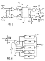
- FIG. 5 represents the slave part PE of the generators.
- This circuit receives the signals PHP1, PHP2 from corresponding amplifiers of the generator master. These signals are processed by a set of logic circuits supplying signals CK1A and CK2A results respectively of the logical AND operation of a between PHP1 and PHP2 and between PHP1 and the complement of PHP2. Signals CK1A and CK2B have respectively the appearance of signals CK1 and CK2 of the figure 3.
- the signals E1, E2 respectively reverse of CK1A, CK2A are then processed by a delay circuit variable 7 delivering two delayed signals Y1, Y2 in function of the RE adjustment command.
- the realization details of circuit 7 will be given with reference to figure 8.
- Signals Y1 and Y2 are each applied to the entry of a NOR gate in order to provide the signals CK1B and CK2B identical to signals Y1 and Y2 when NOR gates are validated by authorization signals applied to the second entrance of each of these doors.
- the CK1B and CK2B signals are then amplified by CIB amplifiers with adjustable impedance according to IS-E tuning parameters to provide signals adjusted clock CK1 and CK2.
- FIG. 6 shows the block diagram of IPC amplifiers when applied to primary generator.
- the amplifier consists essentially several modules M1, M2, ..., M5 mounted in parallel and each receiving the signal clock to be set (PHP1B in the case of the example shown), after possibly validation by through a logic gate controlled by a validation signal.
- Each module M1 to M5 is in fact a 3-state amplifier controlled by one of the bits of IS adjustment parameters and dimensioned to present a determined impedance.
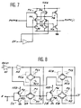
- CMOS realization of these modules is represented in figure 7. It is carried out by means of 4 n channel transistors: NA, ND, NC, NE and 4 transistors p channel: PB, PH, PG, PF.
- the PG and NC transistors are connected in series between the positive voltage Vdd and the mass via the drain-source path of the NE transistor and receive the signal on their gate input PHP1B.
- the PB and NA transistors are connected in series between Vdd and ground and their grids are connected respectively in common on the one hand with PG and NE and on the other hand to NC and NE.
- the PH, PF and ND are respectively connected in parallel with the PG, NE and NC transistors.
- Grids of PF transistors and ND are linked together and constitute the entrance to EN validation of the module.
- EN constitutes the entry of a inverter whose output is connected to the grids of the NE and PH transistors.
- the common point between PB and NA constitutes the amplifier's PHP1 (j) output.
- PB and NA constitute two inverters connected in cascade of which the PHP1 output (j) reproduces the PHP1B input.
- the output impedance of each module is determined by the resistance of the drain-source paths of the PB transistors and NA which can be determined by dimensioning the width of these transistors.
- NA the resistance of the drain-source paths of the PB transistors
- the IS adjustment parameters will then be chosen so to validate the modules whose paralleling presents the appropriate impedance.
- Variable delay circuit 7 can be implemented in accordance with French patent application number 2,666,183 published February 28, 1992 and having as title "Adjustable time constant circuit and application to a adjustable delay circuit " where a time constant circuit has several transfer doors composed of type transistors MOS, whose drain-source paths constitute resistant elements. The time constant is adjustable by activating selectively the transfer doors, the circuit capacity being the structural capacity of the MOS transistors.
- this circuit is made at by means of a plurality of modules in accordance with FIG. 8 whose points E, X and Y are connected respectively between them, E constituting one of the inputs E1 or E2 while Y constitutes one of its outputs Y1 or Y2.
- Each module according to FIG. 8 is validated as a function of one of the bits RE (x) of the adjustment word RE.
Landscapes
- Engineering & Computer Science (AREA)
- Theoretical Computer Science (AREA)
- Physics & Mathematics (AREA)
- General Engineering & Computer Science (AREA)
- General Physics & Mathematics (AREA)
- Stabilization Of Oscillater, Synchronisation, Frequency Synthesizers (AREA)
- Tests Of Electronic Circuits (AREA)
- Information Transfer Systems (AREA)
- Dram (AREA)
Claims (12)
- Verfahren zum Steuern von Taktsignalen (PHP1, PHP2, CK1, CK2) in einem synchronen System des Typs, der mehrere Einheiten (CMU, CPU, IOU, SCU, MU, BDP, EAD, FPP, DIR, DAT), enthält, die durch die Taktsignale synchronisiert werden, die ausgehend von einem Basistaktsignal (H) von wenigstens einem Generator (ARG) geliefert werden, der Mittel zum Steuern (6, 7, CIB) der Taktsignale enthält, wobei die Steuermittel durch digitale Steuerparameter (IS, RM, RE) gesteuert werden, wobei das Verfahren dadurch gekennzeichnet ist, daß es die folgenden Schritte enthält:1) vor dem Start des Systems: Bestimmen des optimalen Wertes der Steuerparameter (IS, RM, RE), der den Taktsignalen in einem dem Generator (ARG) zugeordneten nichtflüchtigen Speicher (1) Referenz- und Ladeeigenschaften der optimalen Werte verleiht,2) bei jedem Start des Systems: Lesen des Speichers und Steuern der Steuermittel durch den im Speicher gelesenen Wert, wobei das Lesen des Speichers (1) durch eine durch die Taktsignale (CK1, CK2) synchronisierte Leseschaltung (PS) ausgeführt wird, wobei das Lesen des Speichers von einer Erfassung des Vorhandenseins von Lesefehlern begleitet wird, wobei bei Abwesenheit von Fehlern die Steuermittel direkt durch den im Speicher (1) gelesenen Wert gesteuert werden und die Steuermittel im Fehlerfall durch einen modifizierten Wert der Steuerparameter gesteuert werden, wobei dem ersten Lesen des Speichers ein Schritt vorhergeht, der darin besteht, die Steuermittel durch einen an die Steuerparameter angenäherten Wert zu steuern.
- Verfahren nach Anspruch 1, dadurch gekennzeichnet, daß die Parameter in binärer digitaler Form vorliegen, wobei den optimalen Werten ein Fehlererfassungscode zugeordnet ist, der ebenfalls in den Speicher (1) geladen ist, und daß nach dem Lesen des Speichers (1) eine Fehlererfassungsoperation mittels des Fehlererfassungscodes ausgeführt wird.
- Verfahren nach Anspruch 2, dadurch gekennzeichnet, daß der Code ein Fehlerkorrekturcode ist, der wenigstens die Korrektur eines einfachen Fehlers ermöglicht, und daß bei einer Erfassung eines einfachen Fehlers der modifizierte Wert der gelesene und kraft dieses Codes korrigierte Wert ist.
- Verfahren nach einem der Ansprüche 1 bis 3, dadurch gekennzeichnet, daß der angenäherte Wert jener der Steuerung ist, die anzuwenden ist, wenn die Schaltungen des Generators und der Einheiten die wahrscheinlichsten Eigenschaften unter jenen besitzen, die durch das oder die Fertigungsverfahren erhalten werden können, die für die Verwirklichung dieser Schaltungen gewählt werden.
- Verfahren nach einem der Ansprüche 1 bis 4, dadurch gekennzeichnet, daß die Steuerparameter den Steuermitteln die auf die gesendeten Taktsignale anzuwendende Amplitudenkorrektur (IS) mitteilen.
- Verfahren nach Anspruch 5, dadurch gekennzeichnet, daß weitere Steuerparameter (RM, RE) den Steuermitteln die auf die gesendeten Taktsignale anzuwendende Phasenkorrektur mitteilen.
- Synchrones System, das mehrere Einheiten (CMU, CPU, IOU, SCU, MU, BDP, EAD, FPP, DIR, DAT) enthält, die durch Taktsignale (PHP1, PHP2, CK1, CK2) ausgehend von einem Basistaktsignal (H) synchronisiert sind, die von wenigstens einem Generator (ARG) geliefert werden, der Steuermittel (6, 7, CIB) für die Taktsignale enthält, wobei die Steuermittel durch digitale Steuerparameter (IS, RM, RE) gesteuert werden, dadurch gekennzeichnet, daß dem Generator (ARG) ein nichtflüchtiger Speicher (1) zugeordnet ist, der den optimalen Wert der Steuerparameter enthält, der den technologischen Eigenschaften der den Generator und/oder die von ihm synchronisierten Einheiten bildenden Schaltungen entspricht, wobei der Wert vor einem Start des Systems bestimmt und in den Speicher geladen worden ist, und daß das System Mittel (PS, mP) zum Lesen des Speichers (1) sowie Übertragungsmittel (CMB, 2, 3) enthält, die mit den Lesemitteln verbunden sind, um die Steuermittel in Abhängigkeit von dem im Speicher bei jedem Start des Systems gelesenen Wert zu steuern, wobei die Lesemittel eine synchrone Schaltung (PS), die durch die Taktsignale (CK1, CK2) synchronisiert ist, enthält und es die Übertragungsmittel ermöglichen, die Steuermittel entweder in Abhängigkeit von einem vorgegebenen Wert (RF) der Steuerparameter vor dem ersten Lesen des Speichers oder in Abhängigkeit von dem gelesenen Wert zu steuern, wobei den Steuerparametern (IS, RM, RE) ein Erfassungscode und/oder ein Fehlerkorrekturcode zugeordnet sind und die Lesemittel Mittel (mP) zum Erfassen und/oder Korrigieren der Fehler enthalten, die die gelesenen Parameter beeinflussen können, so daß die Steuermittel bei Abwesenheit eines Fehlers direkt durch den im Speicher (1) gelesenen Wert gesteuert werden und daß die Steuermittel im Fehlerfall durch einen modifizierten Wert der Steuerparameter gesteuert werden.
- Synchrones System nach Anspruch 7, dadurch gekennzeichnet, daß die Steuermittel Steuerschaltungen und ein Steuerregister (RT) zum Speichern der Steuerparameter enthalten, wobei der Ausgang des Registers (RT) die Steuerschaltungen aktiviert.
- Synchrones System nach Anspruch 8, dadurch gekennzeichnet, daß die Steuerschaltungen Amplitudensteuerschaltungen (CIB) und/oder Phasensteuerschaltungen (PM, PE) für die Taktsignale sind.
- Synchrones System nach Anspruch 9, dadurch gekennzeichnet, daß die Lesemittel ein Mikroprozessorsystem (mP) und Schnittstellenschaltungen (IF, IO, 2) zwischen dem Mikroprozessorsystem und einerseits der synchronen Schaltung (PS) und andererseits dem Steuerregister (RT) enthalten, und daß die synchrone Schaltung (PS) und die Schnittstellenschaltungen so beschaffen sind, daß sie das Lesen des Speichers (1) bzw. das Schreiben in das Register (RT) unter der Steuerung des Mikroprozessorsystems ausführen.
- Synchrones System nach Anspruch 10, dadurch gekennzeichnet, daß es einerseits einen primären Generator (ARG-M), der einen Master-Abschnitt (PM) und einen Slave-Abschnitt (PE) besitzt, und andererseits mehrere sekundäre Generatoren (ARG-E), die einen Slave-Abschnitt (PE) besitzen, enthält, daß der Master-Abschnitt (PM) des primären Generators (ARG-M) an die Slave-Abschnitte (PE) Master-Taktsignale (PHP1, PHP2) ausgehend von einem Basistakt (H) liefert, daß jeder der Slave-Abschnitte (PE) der Generatoren (ARG) Slave-Taktsignale (CK1, CK2) ausgehend von den Master-Taktsignalen (PHP1, PHP2) liefert und daß das Mikroprozessorsystem (mP) mit jedem der Steuermittel der Generatoren (ARG) über eine gemeinsame Schnittstelle (CMB) verbunden ist.
- Synchrones System nach Anspruch 11, dadurch gekennzeichnet, daß der primäre Generator (ARG-M) und das Mikroprozessorsystem (mP) einen Teil einer elektronischen Wartungskarte (CMU) bilden, daß jeder sekundäre Generator (ARG-E) einen Teil einer Systemkarte (CPU, IOU, SCU, MU) bildet und daß die Schaltungen jeder Karte durch die Slave-Taktsignale (CK1, CK2), die von dem der Karte zugeordneten sekundären Generator erzeugt werden, synchronisiert werden.
Applications Claiming Priority (2)
| Application Number | Priority Date | Filing Date | Title |
|---|---|---|---|
| FR9010805 | 1990-08-30 | ||
| FR9010805A FR2666424B1 (fr) | 1990-08-30 | 1990-08-30 | Procede et dispositif de reglage des signaux d'horloge dans un systeme synchrone. |
Publications (2)
| Publication Number | Publication Date |
|---|---|
| EP0474541A1 EP0474541A1 (de) | 1992-03-11 |
| EP0474541B1 true EP0474541B1 (de) | 1999-06-09 |
Family
ID=9399956
Family Applications (1)
| Application Number | Title | Priority Date | Filing Date |
|---|---|---|---|
| EP91402322A Expired - Lifetime EP0474541B1 (de) | 1990-08-30 | 1991-08-28 | Verfahren und Vorrichtung zur Taktsignalregelung in einem Synchronsystem |
Country Status (5)
| Country | Link |
|---|---|
| US (1) | US5305453A (de) |
| EP (1) | EP0474541B1 (de) |
| JP (1) | JPH04256114A (de) |
| DE (1) | DE69131310T2 (de) |
| FR (1) | FR2666424B1 (de) |
Families Citing this family (14)
| Publication number | Priority date | Publication date | Assignee | Title |
|---|---|---|---|---|
| JPH05268016A (ja) * | 1992-02-19 | 1993-10-15 | Nec Corp | 半導体集積回路 |
| US5640523A (en) * | 1994-09-02 | 1997-06-17 | Cypress Semiconductor Corporation | Method and apparatus for a pulsed tri-state phase detector for reduced jitter clock recovery |
| JPH08123520A (ja) * | 1994-10-25 | 1996-05-17 | Mitsubishi Electric Corp | 駆動制御指令装置と複数台の駆動制御指令装置の同期制御システム及びその同期制御方法 |
| US5455540A (en) * | 1994-10-26 | 1995-10-03 | Cypress Semiconductor Corp. | Modified bang-bang phase detector with ternary output |
| FR2767935B1 (fr) * | 1997-09-04 | 1999-11-12 | Bull Sa | Procede pour synchroniser un systeme informatique et systeme informatique ainsi synchronise |
| US6304517B1 (en) | 1999-06-18 | 2001-10-16 | Telefonaktiebolaget Lm Ericsson (Publ) | Method and apparatus for real time clock frequency error correction |
| JP3880302B2 (ja) * | 2000-10-12 | 2007-02-14 | 富士通株式会社 | 位相合成回路およびタイミング信号発生回路 |
| US20020061107A1 (en) * | 2000-09-25 | 2002-05-23 | Tham Terry K. | Methods and apparatus for implementing a cryptography engine |
| US20020078342A1 (en) * | 2000-09-25 | 2002-06-20 | Broadcom Corporation | E-commerce security processor alignment logic |
| US6621882B2 (en) | 2001-03-02 | 2003-09-16 | General Dynamics Information Systems, Inc. | Method and apparatus for adjusting the clock delay in systems with multiple integrated circuits |
| US20030084360A1 (en) * | 2001-08-21 | 2003-05-01 | Grant David Alexander | Method of synchronizing and phase staggering two or more sampled data systems |
| US7372928B1 (en) | 2002-11-15 | 2008-05-13 | Cypress Semiconductor Corporation | Method and system of cycle slip framing in a deserializer |
| US8085857B1 (en) | 2003-09-25 | 2011-12-27 | Cypress Semiconductor Corporation | Digital-compatible multi-state-sense input |
| US10037213B2 (en) | 2016-09-19 | 2018-07-31 | Nxp Usa, Inc. | System and method for adjusting boot interface frequency |
Family Cites Families (14)
| Publication number | Priority date | Publication date | Assignee | Title |
|---|---|---|---|---|
| NL7014137A (de) * | 1970-09-25 | 1972-03-28 | ||
| US3809884A (en) * | 1972-11-15 | 1974-05-07 | Honeywell Inf Systems | Apparatus and method for a variable memory cycle in a data processing unit |
| FR2498035B1 (fr) * | 1981-01-09 | 1986-01-17 | Thomson Csf | Procede et dispositif de synchronisation de messages |
| US4509120A (en) * | 1982-09-30 | 1985-04-02 | Bell Telephone Laboratories, Inc. | Variable cycle-time microcomputer |
| US4637018A (en) * | 1984-08-29 | 1987-01-13 | Burroughs Corporation | Automatic signal delay adjustment method |
| JPH02501613A (ja) * | 1987-03-16 | 1990-05-31 | シーメンス、アクチエンゲゼルシヤフト | Mosトランジスタを有するゲート回路 |
| DE3784496T2 (de) * | 1987-06-11 | 1993-09-16 | Ibm | Taktgeneratorsystem. |
| US5086500A (en) * | 1987-08-07 | 1992-02-04 | Tektronix, Inc. | Synchronized system by adjusting independently clock signals arriving at a plurality of integrated circuits |
| NL8802532A (nl) * | 1988-10-14 | 1990-05-01 | Philips Nv | Data-verwerkend systeem met klokpulsgenerator. |
| US5008636A (en) * | 1988-10-28 | 1991-04-16 | Apollo Computer, Inc. | Apparatus for low skew system clock distribution and generation of 2X frequency clocks |
| JPH02126311A (ja) * | 1988-11-04 | 1990-05-15 | Nec Ic Microcomput Syst Ltd | マイクロコンピュータ |
| US4989175A (en) * | 1988-11-25 | 1991-01-29 | Unisys Corp. | High speed on-chip clock phase generating system |
| US5028824A (en) * | 1989-05-05 | 1991-07-02 | Harris Corporation | Programmable delay circuit |
| US5036230A (en) * | 1990-03-01 | 1991-07-30 | Intel Corporation | CMOS clock-phase synthesizer |
-
1990
- 1990-08-30 FR FR9010805A patent/FR2666424B1/fr not_active Expired - Lifetime
-
1991
- 1991-08-28 DE DE69131310T patent/DE69131310T2/de not_active Expired - Fee Related
- 1991-08-28 US US07/750,967 patent/US5305453A/en not_active Expired - Lifetime
- 1991-08-28 EP EP91402322A patent/EP0474541B1/de not_active Expired - Lifetime
- 1991-08-30 JP JP3244881A patent/JPH04256114A/ja active Pending
Also Published As
| Publication number | Publication date |
|---|---|
| EP0474541A1 (de) | 1992-03-11 |
| US5305453A (en) | 1994-04-19 |
| JPH04256114A (ja) | 1992-09-10 |
| DE69131310T2 (de) | 1999-11-04 |
| FR2666424A1 (fr) | 1992-03-06 |
| FR2666424B1 (fr) | 1992-11-06 |
| DE69131310D1 (de) | 1999-07-15 |
Similar Documents
| Publication | Publication Date | Title |
|---|---|---|
| EP0474541A1 (de) | Verfahren und Vorrichtung zur Taktsignalregelung in einem Synchronsystem | |
| US10741237B2 (en) | Strobe-offset control circuit | |
| US8008954B2 (en) | Multi-phase signal generator and method | |
| EP0466591B1 (de) | Verfahren und Anordnung für digitale serielle Datenübertragung | |
| US20050122153A1 (en) | Centralizing the lock point of a synchronous circuit | |
| JP4634803B2 (ja) | データ取得の方法と装置 | |
| FR2827684A1 (fr) | Controleur de memoire presentant une capacite d'ecriture 1x/mx | |
| KR102674031B1 (ko) | 메모리 컨트롤러, 이를 포함하는 메모리 시스템 및 그 동작 방법 | |
| FR2664765A1 (fr) | Dispositif de serialisation et de deserialisation de donnees et systeme de transmission numerique de donnees en serie en resultant. | |
| FR2726381A1 (fr) | Carte intelligente et procede pour acceder a sa memoire de donnees | |
| FR2790887A1 (fr) | Circuit logique protege contre des perturbations transitoires | |
| FR3066033A1 (fr) | Dispositif d'etage tampon, en particulier apte a etre connecte sur un bus du type interface de peripherique serie | |
| US7391255B2 (en) | Semiconductor phase adjustment system module | |
| EP0466593B1 (de) | Datenabtastschaltung und ein digitales Datenübertragungssystem dazu | |
| EP0488893B1 (de) | Verfahren und Vorrichtung zur Übertragung binärer Differenzsignale und Verwendung in Carry-Select-Addierern | |
| EP1020800B1 (de) | Mikroprozessor mit Schutzschaltungen zur Sicherung des Zugangs zu seinen Registern | |
| FR2683060A1 (fr) | Circuit de commande de sortie de donnee. | |
| WO2003034246A2 (fr) | Dispositif de transmission de donnees asynchrones comprenant des moyens de controle de deviation d'horloge | |
| EP3893117B1 (de) | Überprüfungsschaltkreis des inhalts von registern | |
| US7319635B2 (en) | Memory system with registered memory module and control method | |
| FR2903205A1 (fr) | Procede de controle du temps d'evaluation d'une machine d'etat | |
| EP0823088A1 (de) | Verfahren und vorrichtung zur parallelen automatischen prüfung von elektronischen schaltungen | |
| EP0342096A1 (de) | Logischer Signalgenerator und Signal-Sequenzschaltung für Ladungsübertragungsvorrichtung | |
| KR19990001770A (ko) | 프로그래머블 레지스터 제어지연회로 | |
| FR2664421A1 (fr) | Decodeur precharge a autoverrouillage. |
Legal Events
| Date | Code | Title | Description |
|---|---|---|---|
| PUAI | Public reference made under article 153(3) epc to a published international application that has entered the european phase |
Free format text: ORIGINAL CODE: 0009012 |
|
| 17P | Request for examination filed |
Effective date: 19920107 |
|
| AK | Designated contracting states |
Kind code of ref document: A1 Designated state(s): DE ES FR GB GR IT NL SE |
|
| RAP3 | Party data changed (applicant data changed or rights of an application transferred) |
Owner name: BULL S.A. |
|
| RAP1 | Party data changed (applicant data changed or rights of an application transferred) |
Owner name: BULL S.A. |
|
| 17Q | First examination report despatched |
Effective date: 19970530 |
|
| GRAG | Despatch of communication of intention to grant |
Free format text: ORIGINAL CODE: EPIDOS AGRA |
|
| GRAG | Despatch of communication of intention to grant |
Free format text: ORIGINAL CODE: EPIDOS AGRA |
|
| GRAH | Despatch of communication of intention to grant a patent |
Free format text: ORIGINAL CODE: EPIDOS IGRA |
|
| RIN1 | Information on inventor provided before grant (corrected) |
Inventor name: BRINKHUYSEN, JACQUES Inventor name: BOUDRY, JEAN-MARIE |
|
| GRAH | Despatch of communication of intention to grant a patent |
Free format text: ORIGINAL CODE: EPIDOS IGRA |
|
| GRAA | (expected) grant |
Free format text: ORIGINAL CODE: 0009210 |
|
| AK | Designated contracting states |
Kind code of ref document: B1 Designated state(s): DE ES FR GB GR IT NL SE |
|
| PG25 | Lapsed in a contracting state [announced via postgrant information from national office to epo] |
Ref country code: IT Free format text: LAPSE BECAUSE OF FAILURE TO SUBMIT A TRANSLATION OF THE DESCRIPTION OR TO PAY THE FEE WITHIN THE PRESCRIBED TIME-LIMIT;WARNING: LAPSES OF ITALIAN PATENTS WITH EFFECTIVE DATE BEFORE 2007 MAY HAVE OCCURRED AT ANY TIME BEFORE 2007. THE CORRECT EFFECTIVE DATE MAY BE DIFFERENT FROM THE ONE RECORDED. Effective date: 19990609 Ref country code: GR Free format text: LAPSE BECAUSE OF NON-PAYMENT OF DUE FEES Effective date: 19990609 Ref country code: ES Free format text: THE PATENT HAS BEEN ANNULLED BY A DECISION OF A NATIONAL AUTHORITY Effective date: 19990609 Ref country code: SE Free format text: THE PATENT HAS BEEN ANNULLED BY A DECISION OF A NATIONAL AUTHORITY Effective date: 19990609 |
|
| GBT | Gb: translation of ep patent filed (gb section 77(6)(a)/1977) |
Effective date: 19990610 |
|
| REF | Corresponds to: |
Ref document number: 69131310 Country of ref document: DE Date of ref document: 19990715 |
|
| PLBE | No opposition filed within time limit |
Free format text: ORIGINAL CODE: 0009261 |
|
| STAA | Information on the status of an ep patent application or granted ep patent |
Free format text: STATUS: NO OPPOSITION FILED WITHIN TIME LIMIT |
|
| 26N | No opposition filed | ||
| REG | Reference to a national code |
Ref country code: GB Ref legal event code: IF02 |
|
| PGFP | Annual fee paid to national office [announced via postgrant information from national office to epo] |
Ref country code: GB Payment date: 20060801 Year of fee payment: 16 |
|
| PGFP | Annual fee paid to national office [announced via postgrant information from national office to epo] |
Ref country code: DE Payment date: 20060810 Year of fee payment: 16 |
|
| GBPC | Gb: european patent ceased through non-payment of renewal fee |
Effective date: 20070828 |
|
| PG25 | Lapsed in a contracting state [announced via postgrant information from national office to epo] |
Ref country code: DE Free format text: LAPSE BECAUSE OF NON-PAYMENT OF DUE FEES Effective date: 20080301 |
|
| PGFP | Annual fee paid to national office [announced via postgrant information from national office to epo] |
Ref country code: NL Payment date: 20080728 Year of fee payment: 18 |
|
| PG25 | Lapsed in a contracting state [announced via postgrant information from national office to epo] |
Ref country code: GB Free format text: LAPSE BECAUSE OF NON-PAYMENT OF DUE FEES Effective date: 20070828 |
|
| REG | Reference to a national code |
Ref country code: NL Ref legal event code: V1 Effective date: 20100301 |
|
| PG25 | Lapsed in a contracting state [announced via postgrant information from national office to epo] |
Ref country code: NL Free format text: LAPSE BECAUSE OF NON-PAYMENT OF DUE FEES Effective date: 20100301 |
|
| PGFP | Annual fee paid to national office [announced via postgrant information from national office to epo] |
Ref country code: FR Payment date: 20100910 Year of fee payment: 20 |