EP0474002B1 - Abtaster für Druckmuster - Google Patents
Abtaster für Druckmuster Download PDFInfo
- Publication number
- EP0474002B1 EP0474002B1 EP91113819A EP91113819A EP0474002B1 EP 0474002 B1 EP0474002 B1 EP 0474002B1 EP 91113819 A EP91113819 A EP 91113819A EP 91113819 A EP91113819 A EP 91113819A EP 0474002 B1 EP0474002 B1 EP 0474002B1
- Authority
- EP
- European Patent Office
- Prior art keywords
- image
- disc
- subtracting
- sample image
- area
- Prior art date
- Legal status (The legal status is an assumption and is not a legal conclusion. Google has not performed a legal analysis and makes no representation as to the accuracy of the status listed.)
- Expired - Lifetime
Links
Images

Classifications
-
- G—PHYSICS
- G06—COMPUTING OR CALCULATING; COUNTING
- G06T—IMAGE DATA PROCESSING OR GENERATION, IN GENERAL
- G06T7/00—Image analysis
- G06T7/0002—Inspection of images, e.g. flaw detection
- G06T7/0004—Industrial image inspection
- G06T7/0008—Industrial image inspection checking presence/absence
-
- G—PHYSICS
- G06—COMPUTING OR CALCULATING; COUNTING
- G06T—IMAGE DATA PROCESSING OR GENERATION, IN GENERAL
- G06T7/00—Image analysis
- G06T7/0002—Inspection of images, e.g. flaw detection
- G06T7/0004—Industrial image inspection
- G06T7/001—Industrial image inspection using an image reference approach
-
- G—PHYSICS
- G06—COMPUTING OR CALCULATING; COUNTING
- G06V—IMAGE OR VIDEO RECOGNITION OR UNDERSTANDING
- G06V10/00—Arrangements for image or video recognition or understanding
- G06V10/70—Arrangements for image or video recognition or understanding using pattern recognition or machine learning
- G06V10/74—Image or video pattern matching; Proximity measures in feature spaces
- G06V10/75—Organisation of the matching processes, e.g. simultaneous or sequential comparisons of image or video features; Coarse-fine approaches, e.g. multi-scale approaches; using context analysis; Selection of dictionaries
- G06V10/751—Comparing pixel values or logical combinations thereof, or feature values having positional relevance, e.g. template matching
-
- G—PHYSICS
- G06—COMPUTING OR CALCULATING; COUNTING
- G06V—IMAGE OR VIDEO RECOGNITION OR UNDERSTANDING
- G06V10/00—Arrangements for image or video recognition or understanding
- G06V10/98—Detection or correction of errors, e.g. by rescanning the pattern or by human intervention; Evaluation of the quality of the acquired patterns
- G06V10/993—Evaluation of the quality of the acquired pattern
-
- G—PHYSICS
- G11—INFORMATION STORAGE
- G11B—INFORMATION STORAGE BASED ON RELATIVE MOVEMENT BETWEEN RECORD CARRIER AND TRANSDUCER
- G11B23/00—Record carriers not specific to the method of recording or reproducing; Accessories, e.g. containers, specially adapted for co-operation with the recording or reproducing apparatus ; Intermediate mediums; Apparatus or processes specially adapted for their manufacture
- G11B23/38—Visual features other than those contained in record tracks or represented by sprocket holes the visual signals being auxiliary signals
- G11B23/40—Identifying or analogous means applied to or incorporated in the record carrier and not intended for visual display simultaneously with the playing-back of the record carrier, e.g. label, leader, photograph
-
- G—PHYSICS
- G06—COMPUTING OR CALCULATING; COUNTING
- G06T—IMAGE DATA PROCESSING OR GENERATION, IN GENERAL
- G06T2207/00—Indexing scheme for image analysis or image enhancement
- G06T2207/30—Subject of image; Context of image processing
- G06T2207/30108—Industrial image inspection
- G06T2207/30144—Printing quality
Definitions
- the invention relates to a method and apparatus of determining defects in a printed area according to the preambles of claims 1 and 11, respectively, as disclosed in EP-A-0 194 331 and, more specifically, to a print scanner for determining defects in the printing of a compact disc label.
- the method according to the present invention is accomplished by means of the method of claim 1 and the apparatus of claim 11, respectively.
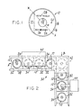
- FIG. 1 is a plan view of a compact disc illustrating printing defects which can occur in the label thereof.
- FIG. 2 is a partially schematic view of a compact disc label printing system with which my print scanner may be used.
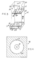
- FIG. 3 is a perspective view of the camera station of my print scanner.
- FIG. 4 is a plan view illustrating the mask incorporated in my print scanner.
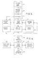
- FIG. 5 is a block diagram illustrating a portion of the hardware of my print scanner.
- FIG. 6 is a block diagram illustrating another part of the hardware of my print scanner.
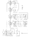
- FIG. 7 is a flow diagram illustrating part of the operation of my print scanner.
- FIG. 8 is a flow diagram illustrating another portion of the operation of my print scanner.
- a compact disc indicated generally by the reference character 10
- a central area 14 within the ID ring carrying no printing
- a major area 16 thereof to which printing may be applied and a narrow peripheral area 18 carrying no printing.
- the disc is to carry the legend "Remarkable Recordings" in bold letters.
- certain defects which may occur in the course of the printing process. These include a number of excess ink defects such as a spot 20 in which no ink should be present, a line 22 extending along a chord of the disc, a filling in 24 of a letter or a printing 26 of a letter with excess ink.
- a missing ink defect is illustrated by the area 28 of the word "REMARKABLE".
- my print scanner can detect all of these defects. It can detect a defect diameter as small as 0.38 mm (15 thousandths of an inch).
- disc printing apparatus indicated generally by the reference character 30 to which my print scanner can be applied includes a plurality of disc carriers 32, each of which has a recess 34 for receiving a disc 10.
- the disc conveyor comprises a pair of spaced rails 36 and 38 having a right angle bend at one point along their lengths so that the direction of movement of the carriers is changed by 90 degrees. More specifically, the conveyor comprises a first push rod (not shown) or the like for advancing the carriers in steps in the direction of the arrow A in FIG. 2. A second pusher (not shown) or the like moves the carriers in the direction of the arrow B. Since the conveyor per se forms no part of my invention, it will not be described in further detail.
- the carriers 32 move the discs 10 through a printing station 40 whereat the label information is applied to the discs in a manner known to the art. It will readily be appreciated that the station 40 may span a number of carriers 32.
- a disc After leaving the printing station 40 and having received all of the printing for the label, a disc is moved into a camera station indicated generally by the reference character 42 whereat my print scanner is located.
- the carrier 32 stops at this station for a sufficient period of time to permit the inspection operation to take place.
- the carriers After leaving the camera station 42, the carriers move past a robot station at which a robot 44 having an arm 46 is located.
- my system is so arranged as to send a defect signal to the robot 44 concomitantly with the arrival at the robot station of the disc 10 having the defective label.
- the robot removes the disc and places it among the defects.
- the camera station 42 at which my scanner is located includes a light-tight housing 48 formed with a tunnel 50 through which the carriers 32 enter in the direction of the arrow A and an exit tunnel 52 from which the carriers 32 emerge in the direction of the arrow B.
- the location of the camera station has been chosen at a point at which the entire label has been applied to the compact disc and at which the motion path of the robot 44 will not be impeded.
- the exit tunnel 52 is at 90 degrees to the entrance tunnel 50.
- the clearance heights for the tunnels 50 and 52 are based on the heights of the disc carriers 32.
- the inner walls of the housing 48 can be reflected off the surface of the disc 10, appearing as "shadow” regions, reducing the ability to detect defects in the area they eclipse owing to a loss in contrast between the ink and the background illumination reflected off the disc. I so construct the camera station that the walls of the housing 48 are sufficiently far from the center of each disc as to eliminate the eclipse effect.
- the inner walls are painted gloss white to minimize light loss due to absorption.
- a diffraction grating such as a compact disc is illuminated with a white light source whose size is smaller than that of the grating, diffraction glare results.
- a light diffuser positioned within the housing below the sources includes an upper clear plexiglass layer 62, an intermediate layer of diffusing paper 64 and a lower layer 66 of yellow plexiglass.
- I mount the assembly of the layers 62, 64 and 66 in slots in the inside of the walls of the housing 48 to prevent shadow reflections from reaching the camera to be described.
- a hole 68 through the diffuser assembly permits the camera to view the disc.
- CCD charge-coupled device
- Bracket 72 also holds the camera so that its horizontal scan lines make a 45 degree angle with the text line contained on the label of the disc being scanned, as indicated by the line X-X in FIG. 1. This configuration eliminates "video flicker" which increases the probability of false rejects. Parallel text such as that shown on the disc 10 in FIG. 1 contributes to the majority of video noise problems which are reduced by the 45 degree rotation.
- I form one of the walls of the housing 48 with a vent 74 to admit cooling air.
- An outlet port 76 in the top of the housing 48 may be connected to a fan or the like which draws exhaust air from inside the housing to eliminate heat buildup from the lamps in the camera.
- the housing 48 with a disc viewing mask 78 at a small distance above the disc within the camera station.
- the mask 78 may be held in position by means of slots in three of the walls of the housing 48 to prevent attachment shadow reflections off the disc surface and into the camera.
- Mask 78 permits the camera to view only those regions which are vital to label inspection.
- the mask 78 (Fig 4) has a transparent area 80 extending radially inwardly from just inside the periphery of the disc to an inner opaque area 82 which covers the region 14 of the disc, as well as the hole 12.
- Mask 78 also prevents the camera from seeing background conveyor motion.
- Opaque area 82 masks out the disc ID ring, as well as any debris in the center of the disc carrier.
- I provide the housing 48 with a hinged lid 84 which may be opened for access to the bulbs and the camera.
- the video output from the camera 70 is fed to a conveyer display monitor 85 and to a framegrabber 86 which may, for example, be a DT 2851 high resolution framegrabber produced by Data Translation Inc. of Marlboro, Mass.
- the framegrabber digitizes the analog video signal and stores an image in one of two onboard frame-store memories.
- the framegrabber 86 communicates with an 80286 based computer 88.
- An auxiliary frame processor 90 which -may for example be a Data Translation DT2858, communicates with the framegrabber 86 and the computer 88.
- a parallel printer port 92 supplies data to and receives data from the computer 88.
- Conveyor signals indicated by a block 96 are transferred from 24 volts DC to 5 volts DC and sent to the parallel printer port 92 via an IMREC IR1 interface board 94.
- Reject signals produced by the computer 88 exit the parallel printer port 92 and are transferred from 5 volts DC to 24 volts DC via the interface 94 and fed to a reject block 98.
- FIG. 6 also associated with the computer 88 are an Intel 80287 math processor, a hard disc controller and drive 102, a floppy disc controller and drive 104, and a video controller and monitor 106.
- the framegrabber 86 can store two video frames while one additional frame can be stored in a custom configured portion of the extended random access memory of computer 88. Figures of merit are determined using the processing capabilities of the 80286 CPU 88 and the 80287 processor 100.
- the software which controls the print scanner will run in either one of two modes, the first of which is the "control mode” in which commands may be given to the scanner by the operator and the second of which is the "production mode” in which the scanner inspects discs throughout the production run.
- the program On startup, as indicated by the block 110, the program first initializes the hardware and subroutines as indicated by block 112, resets the program variables as indicated by block 114, and then displays the menu on the control monitor 106 as indicated by block 116.
- the control mode the operator is instructed to select one of the following functions:
- the scanner first measures the light levels and calibrates accordingly, as indicated by block 126.
- the F1 flag is set as indicated by block 128, and the scanner averages and acquires 128 reference frames, as indicated by block 130.
- the system sets the flag for F2 as indicated by block 134, and then revises the reference for 128 frames as indicated by block 136.
- function F3 corresponding to starting of a line after a stop is chosen, the system first checks the F1 flag as indicated by block 138 before proceeding.
- the flags and disc counters first are reset as indicated by block 140 and the menu is again displayed. If no function is chosen, the menu continues to be displayed.
- the reference picture is taken as indicated by block 130.
- an accumulator averages 128 frames to keep video noise to an absolute minimum.
- the system first checks to see if the operator has pressed ESCAPE as indicated by block 142. If so, the menu is again displayed. If not, a check is made to see whether or not a disc is beneath the camera as indicated by block 144. If not, the system recycles until a disc is positioned beneath the camera. When that occurs as indicated by block 146, the defective disc shift register is incremented one position. Next, the compact disc label is tested as indicated by block 148. It will readily be appreciated that scans for print defects take place only when the conveyor is not in motion.
- the framegrabber 86 provides 512x512x8-bit resolution for sharp spatial clarity and 256 gray levels.
- each stored image is made up of 262,144 pixels.
- Each subtraction operation is carried out on a pixel-by-pixel basis between the text or sample and reference frames.
- the subtraction operation is performed in both directions, reference from test and test from reference, since the frame grabber converts all negative numbers that are the result of a subtraction to a value of zero. It will readily be appreciated that failure to subtract in both directions reduces the ability to detect either added ink or missing ink.
- the result of the subtraction operation is placed in a section of RAM apart from where the two original frames resided to avoid the loss of the reference frame.
- the defects calculation is based on statistics taken from the subtracted result. From the subtracted result I obtain a histogram which contains the frequency of occurrence of the possible 256 gray levels of the subtracted result. This is indicated by block 158. In addition, the sum of all gray levels of each of the 262,144 pixels in the subtracted result is calculated. With the zeroth element representing a frequency of occurrence of gray level zero of the histogram and the sum, I calculate a "figure of merit" for the test label which is equal to the sum divided by the zeroth element of the histogram. Under this formula a perfect label has a figure of merit of zero and a defective label has a figure of merit which is greater than zero and proportionate to the size and contrast of the defect. This step is indicated by the block 160.
- Fr is the "reference video frame” which is the average of 128 video frames.
- Fs is the "sample video frame" which is the average of 6 video frames.
- Fa is the "analysis video frame" which is the result of a subtraction between Fr and Fs.
- P(RC) is the pixel gray level value at some row R and column C of the analysis video frame Fa.
- H(Fa) is a 256 element histogram representing the frequencies of occurrence of gray levels 0 through 255.
- FOM is the print quality "figure of merit”.
- the histogram H (Fa) would appear as:
- a reject signal is sent through a software shift register so that it reaches the robot 44 at the same time the disc does.
- the signal is converted from 5 volts to 24 volts by interface 94.
- robot 44 places the disc on a printing reject spindle (not shown). This procedure is indicated at block 176.
- the control monitor is updated at 178 and the program returns to 144 to determine whether or not a disc is beneath the camera.
Landscapes
- Engineering & Computer Science (AREA)
- Theoretical Computer Science (AREA)
- Quality & Reliability (AREA)
- Computer Vision & Pattern Recognition (AREA)
- Physics & Mathematics (AREA)
- General Physics & Mathematics (AREA)
- Multimedia (AREA)
- Computing Systems (AREA)
- Artificial Intelligence (AREA)
- Databases & Information Systems (AREA)
- Evolutionary Computation (AREA)
- General Health & Medical Sciences (AREA)
- Medical Informatics (AREA)
- Software Systems (AREA)
- Health & Medical Sciences (AREA)
- Image Processing (AREA)
- Investigating Materials By The Use Of Optical Means Adapted For Particular Applications (AREA)
- Inking, Control Or Cleaning Of Printing Machines (AREA)
- Image Analysis (AREA)
Claims (20)
- Verfahren zum Feststellen von Fehlern in einem bedruckten Bereich, umfassend die Verfahrensschritte
Speichern eines Referenzbilds, das aus einer Vielzahl von Pixeln eines akzeptablen Bereichs gebildet ist, Beschaffen eines Probenbildes, das eine Vielzahl von Pixeln eines Prüfbereichs umfaßt, und pixelweises Subtrahieren des einen der Bilder von dem anderen Bild, um eine Reihe von Grauwertdifferenzen zu erhalten,
gekennzeichnet durch die folgenden Verfahrensschritte:
Subtrahieren des Probenbilds von dem Referenzbild als ein Maß für unerwünschte Druckfarbe in dem Prüfbereich und Subtrahieren des Referenzbilds von dem Probenbild als ein Maß für fehlende Druckfarbe in dem Prüfbereich. - Verfahren nach Anspruch 1, gekennzeichnet durch folgenden Verfahrensschritt:
Modifizieren der Reihe von Grauwertdifferenzen durch Umwandeln jeder Differenz mit negativer Polarität in Null und Erhalten der Grauwertsumme (Schritte 160, 172) der modifizierten Reihe von Differenzen. - Verfahren nach Anspruch 2, bei dem das eine der Bilder das Referenzbild ist und das andere Bild das Probenbild ist und das ferner folgenden Verfahrensschritt umfaßt:
Verwenden der Summe zum Bestimmen einer Gütezahl für fehlende Druckfarbe (Schritt 160) in dem Prüfbereich. - Verfahren nach Anspruch 2, bei dem das eine der Bilder das Probenbild ist und das andere Bild das Referenzbild ist und das ferner folgenden Verfahrensschritt umfaßt:
Verwenden der Summe zum Bestimmen einer Gütezahl für unerwünschte Druckfarbe (Schritt 172) in dem Prüfbereich. - Verfahren nach Anspruch 2, das ferner folgenden Verfahrensschritt umfaßt:
Berechnen eines Histogramms (Schritte 158, 170) der modifizierten Reihe von Differenzen. - Verfahren nach Anspruch 5, das ferner folgenden Verfahrensschritt umfaßt:
Berechnen einer Gütezahl durch Dividieren der Summe durch das nullte Element des Histogramms. - Verfahren nach Anspruch 5, das ferner folgenden Verfahrensschritt umfaßt:
Berechnen einer Gütezahl FOM aus der Beziehung:wobei 0 < P(RC) < N2, H(Fa) ein Histogramm mit N2 + 1 Elementen der Häufigkeit des Auftretens von Grauwerten 0 bis N2 ist undP(RC) der Zahlenwert eines Pixel-Grauwerts ist, der in einer Zeile R und einer Spalte C eines Analyse-Videobildes Fa auftritt, welches sich aus der Subtraktion eines Referenz-Videobildes Fr von einem Proben-Videobild Fs für Druckfarbenmangelfehler und aus einer Subtraktion des Fs von dem Fr für Druckfarbenüberschußfehler ergibt, wobei Fa N1 + 1 Zeilen und Spalten aufweist,wobei Fr das Mittel aus einer ersten vorbestimmten Anzahl von Videobildern ist, undFs das Mittel aus einer zweiten Anzahl von Videobildern ist.
 - Verfahren nach Anspruch 1, bei dem der Schritt des Beschaffens des Probenbilds die folgenden Verfahrensschritte umfaßt:
Erhalten einer Mehrzahl von Bildern (Schritt 152) des Prüfbereichs und Mittelung über dieselben. - Verfahren nach Anspruch 1, bei dem der Schritt des Speicherns des Referenzbilds die folgenden Verfahrensschritte (Schritte 126, 132) umfaßt:
Beleuchten des akzeptablen Bereichs, Erhalten von zwei Bildern desselben, Subtrahieren des einen der Bilder von dem anderen Bild und Speichern der größten Differenz von Grauwerten als ein Maß sowohl für das Rauschen als auch für den Beleuchtungslichtpegel. - Verfahren nach Anspruch 1, bei dem der Schritt des Speicherns des Referenzbilds folgende Verfahrensschritte (130) umfaßt:
Erhalten einer Mehrzahl von Bildern des akzeptablen Bereichs und Mittelung über dieselben. - Vorrichtung zum Feststellen von Fehlern in einem bedruckten Bereich, umfassend Mittel zum Speichern eines Referenzbilds, das aus einer Vielzahl von Pixeln eines akzeptablen Bereichs gebildet ist, Mittel zum Beschaffen eines Probenbilds, das eine Vielzahl von Pixeln eines Prüfbereichs umfaßt, und Mittel (86) zum pixelweisen Subtrahieren des einen der Bilder von dem anderen Bild, um eine Reihe von Grauwertdifferenzen zu erhalten,
dadurch gekennzeichnet, daß die Mittel (86) zum Subtrahieren als Mittel zum Subtrahieren des Probenbilds von dem Referenzbild als ein Maß für unerwünschte Druckfarbe in dem Prüfbereich und als Mittel zum Subtrahieren des Referenzbilds von dem Probenbild als ein Maß für fehlende Druckfarbe in dem Prüfbereich ausgebildet sind. - Vorrichtung nach Anspruch 11, wobei Mittel zum Modifizieren der Reihe von Grauwertdifferenzen durch Umwandeln jeder Differenz mit negativer Polarität in Null und Mittel zum Erhalten der Grauwertsumme (Schritte 160, 172) der modifizierten Reihe von Differenzen vorgesehen sind.
- Vorrichtung nach Anspruch 11, wobei der bedruckte Bereich das Label einer Compact Disc (10) ist, welche eine mittige Öffnung (12) und einen daran angrenzenden nicht bedruckten Bereich (14) aufweist, und wobei das Mittel zum Beschaffen des Probenbilds Mittel (56, 58, 60, 62, 64) zum Beleuchten der Disc mit diffusem Licht und Maskierungsmittel (78, 82) zum Abhalten von Beleuchtungslicht von allen Bereichen der Disc außer dem Label umfaßt.
- Vorrichtung nach Anspruch 11, wobei das Mittel zum Subtrahieren Mittel (Schritt 156) zum Subtrahieren des Referenzbilds von dem Probenbild als ein Maß für fehlende Druckfarbe und Mittel (168) zum Subtrahieren des Probenbilds von dem Referenzbild als ein Maß für unerwünschte Druckfarbe umfaßt.
- Vorrichtung nach Anspruch 11, wobei der bedruckte Bereich das Label einer Compact Disc ist und wobei das Mittel zum Beschaffen des Probenbilds eine Videokamera (70) und eine Glühlampe (56, 58, 60, 62) und einen Diffusor (64) umfassende Mittel zum Beleuchten des Labels der Disc mit diffusem Licht umfaßt, wobei der Diffusor zwischen der Kamera und der Disc angeordnet ist und eine Öffnung (68) aufweist, durch welche die Kamera das Label aufnehmen kann.
- Vorrichtung nach Anspruch 15, wobei das Mittel zum Beschaffen des Probenbilds ferner Maskierungsmittel (78, 82) umfaßt, die zwischen dem Diffusor und der Disc angeordnet sind, um Beleuchtungslicht von allen Bereichen der Disc außer dem Label abzuhalten.
- Vorrichtung nach Anspruch 11, wobei der bedruckte Bereich das Label einer Compact Disc ist und die Vorrichtung ferner ein im wesentlichen lichtdichtes Gehäuse (48), einen Einlaß (50) zum Zuführen einer Disc in das Gehäuse und einen Auslaß (52), durch den eine Disc das Gehäuse verlassen kann, umfaßt, wobei die Innenwände des Gehäuses lichtreflektierend sind.
- Vorrichtung nach Anspruch 17, wobei der Einlaß und der Auslaß jeweils einen Tunnel umfassen.
- Vorrichtung nach Anspruch 18, wobei die Tunnel Innenwände aufweisen, die lichtabsorbierend sind.
- Vorrichtung nach Anspruch 11, wobei der bedruckte Bereich parallelen Text enthält und wobei das Mittel zum Beschaffen des Probenbilds eine Videokamera umfaßt, die so angeordnet ist, daß ihre horizontalen Abtastzeilen mit dem parallelen Text einen Winkel von 45° einschließen.
Applications Claiming Priority (2)
| Application Number | Priority Date | Filing Date | Title |
|---|---|---|---|
| US07/579,080 US5181081A (en) | 1990-09-06 | 1990-09-06 | Print scanner |
| US579080 | 1990-09-06 |
Publications (4)
| Publication Number | Publication Date |
|---|---|
| EP0474002A2 EP0474002A2 (de) | 1992-03-11 |
| EP0474002A3 EP0474002A3 (en) | 1992-10-14 |
| EP0474002B1 true EP0474002B1 (de) | 1998-06-03 |
| EP0474002B2 EP0474002B2 (de) | 2002-09-11 |
Family
ID=24315488
Family Applications (1)
| Application Number | Title | Priority Date | Filing Date |
|---|---|---|---|
| EP91113819A Expired - Lifetime EP0474002B2 (de) | 1990-09-06 | 1991-08-17 | Abtaster für Druckmuster |
Country Status (4)
| Country | Link |
|---|---|
| US (1) | US5181081A (de) |
| EP (1) | EP0474002B2 (de) |
| JP (1) | JP2975183B2 (de) |
| DE (1) | DE69129518T3 (de) |
Families Citing this family (40)
| Publication number | Priority date | Publication date | Assignee | Title |
|---|---|---|---|---|
| US5165340A (en) * | 1991-03-06 | 1992-11-24 | Karlyn William M | Multicolor printing system for the silk-screen printing of compact discs |
| US5841955A (en) * | 1991-12-02 | 1998-11-24 | Goss Graphic Systems, Inc. | Control system for a printing press |
| JPH06251555A (ja) * | 1993-02-26 | 1994-09-09 | Sony Corp | 記録媒体収納ケース及び記録媒体収納ケースの印刷方法 |
| US5812705A (en) * | 1995-02-28 | 1998-09-22 | Goss Graphic Systems, Inc. | Device for automatically aligning a production copy image with a reference copy image in a printing press control system |
| DE19511197C2 (de) * | 1995-03-27 | 1999-05-12 | Basler Gmbh | Verfahren und Vorrichtung zum optischen Prüfen einer Oberfläche, insbesondere einer Compact-Disc |
| US5767980A (en) | 1995-06-20 | 1998-06-16 | Goss Graphic Systems, Inc. | Video based color sensing device for a printing press control system |
| US5805280A (en) * | 1995-09-28 | 1998-09-08 | Goss Graphic Systems, Inc. | Control system for a printing press |
| US5903712A (en) * | 1995-10-05 | 1999-05-11 | Goss Graphic Systems, Inc. | Ink separation device for printing press ink feed control |
| WO1998010241A1 (en) * | 1996-09-05 | 1998-03-12 | Wea Manufacturing, Inc. | Color printer scanner |
| AU4316297A (en) * | 1996-09-05 | 1998-04-14 | Wea Manufacturing Inc. | Spatial photometric neural network |
| US5946216A (en) * | 1996-11-14 | 1999-08-31 | Cedar Technologies, Inc. | Vertical transport device for recording and verifying plastic disks |
| US5967676A (en) * | 1998-03-31 | 1999-10-19 | Microtech Conversion Systems, Inc. | Image orientation system for disk printing |
| US6630998B1 (en) * | 1998-08-13 | 2003-10-07 | Acushnet Company | Apparatus and method for automated game ball inspection |
| US6266436B1 (en) * | 1999-04-09 | 2001-07-24 | Kimberly-Clark Worldwide, Inc. | Process control using multiple detections |
| US20020087574A1 (en) * | 2000-12-15 | 2002-07-04 | Walsh Terrence P. | Method for automating inspecting labels |
| US7342681B2 (en) * | 2001-07-13 | 2008-03-11 | Transpacific Ip, Ltd | High-speed calibration method and system for an image-capture apparatus |
| US7397939B2 (en) * | 2002-08-30 | 2008-07-08 | Hewlett-Packard Development Company, L.P. | Method and apparatus for automatic removal of optical artifacts in scanning |
| US20050254381A1 (en) * | 2004-04-28 | 2005-11-17 | Desormeaux Joseph Jr | System and method for detecting faulty media in a media player |
| US7567266B2 (en) * | 2004-04-30 | 2009-07-28 | Hewlett-Packard Development Company, L.P. | Media labeling system |
| US7377617B2 (en) * | 2004-10-12 | 2008-05-27 | Clarke Leo C | Printing apparatus and method |
| JP4702363B2 (ja) * | 2005-03-29 | 2011-06-15 | セイコーエプソン株式会社 | メディア処理装置 |
| US20060274617A1 (en) * | 2005-06-03 | 2006-12-07 | Musto James J | Techniques for forming burst cutting area mark |
| US20070090006A1 (en) * | 2005-10-26 | 2007-04-26 | Jeffery Kelsch | Spindle sleeve |
| US7684309B2 (en) * | 2005-11-03 | 2010-03-23 | Cinram International Inc. | Multi-purpose high-density optical disc |
| US7986611B1 (en) | 2007-03-22 | 2011-07-26 | Cinram International Inc. | High-density optical recording media and method for making same |
| US8675464B2 (en) * | 2005-11-03 | 2014-03-18 | Cinram Group, Inc. | Dual sided optical storage media and method for making same |
| ATE386642T1 (de) * | 2005-12-22 | 2008-03-15 | Tapematic Spa | Tintenstrahldruckapparat und verfahren |
| US7910191B1 (en) | 2006-03-09 | 2011-03-22 | Cinram International Inc. | Method for forming light-transmitting cover layer for optical recording medium |
| US20110096655A1 (en) * | 2006-03-09 | 2011-04-28 | Cinram International Inc. | Forming light-transmitting cover layer for recording medium |
| US20080223743A1 (en) * | 2007-03-12 | 2008-09-18 | Gary Lenkeit | Ecofriendly package for CDs and DVDs |
| US7946015B1 (en) | 2007-11-07 | 2011-05-24 | Cinram International Inc. | Method and apparatus for separating dummy disc from multi-layer substrate for optical storage medium |
| US20090127142A1 (en) * | 2007-11-15 | 2009-05-21 | Jeff Rothstein | Optical disc enclosure incorporating fragrance atomizer |
| JP5309678B2 (ja) * | 2008-05-07 | 2013-10-09 | セイコーエプソン株式会社 | ディスク処理装置、及び、ディスク処理装置の制御方法 |
| US8739299B1 (en) | 2009-12-24 | 2014-05-27 | Cinram Group, Inc. | Content unlocking |
| US8369196B1 (en) | 2010-05-04 | 2013-02-05 | Cinram International Inc. | BCA recording on optical recording medium |
| US8526282B1 (en) | 2010-07-07 | 2013-09-03 | Cinram Group, Inc. | Method for replicating media using unique identifiers |
| TWM398179U (en) * | 2010-07-23 | 2011-02-11 | Acard Technology Corp | Automatic inspection device for CD/DVD output printing and printer/burner having the same |
| CN102879404B (zh) * | 2012-10-07 | 2015-06-17 | 复旦大学 | 工业结构化场景中医用胶囊缺陷自动检测的系统 |
| CN104677920B (zh) * | 2015-02-09 | 2017-04-05 | 浙江大学 | 一种基于果面局部灰度突变的水果表面虫眼检测标记方法 |
| GB201803795D0 (en) * | 2018-03-09 | 2018-04-25 | Prisymid Ltd | Label data processing system |
Family Cites Families (8)
| Publication number | Priority date | Publication date | Assignee | Title |
|---|---|---|---|---|
| JPS5419366A (en) * | 1977-07-14 | 1979-02-14 | Nippon Jidoseigyo Ltd | Device for inspecting fault of pattern |
| US4270863A (en) * | 1979-11-01 | 1981-06-02 | Owens-Illinois, Inc. | Method and apparatus for inspecting objects for defects |
| US4579455A (en) * | 1983-05-09 | 1986-04-01 | Kla Instruments Corporation | Photomask inspection apparatus and method with improved defect detection |
| CA1226976A (en) * | 1984-03-30 | 1987-09-15 | Nobuyoshi Nakajima | Method and apparatus for automatically correcting subtraction image density |
| DD224704B1 (de) * | 1984-04-27 | 1987-07-29 | Mikroelektronik Zt Forsch Tech | Verfahren zur inkpunkterkennung und schaltungsanordnung zur durchfuehrung des verfahrens |
| DE3578768D1 (de) * | 1985-03-14 | 1990-08-23 | Toppan Printing Co Ltd | Einrichtung zum ueberpruefen von abdruecken. |
| US4691231A (en) * | 1985-10-01 | 1987-09-01 | Vistech Corporation | Bottle inspection system |
| GB8802940D0 (en) * | 1988-02-09 | 1988-03-09 | Nally R B | Image qualification system |
-
1990
- 1990-09-06 US US07/579,080 patent/US5181081A/en not_active Expired - Lifetime
-
1991
- 1991-08-17 EP EP91113819A patent/EP0474002B2/de not_active Expired - Lifetime
- 1991-08-17 DE DE69129518T patent/DE69129518T3/de not_active Expired - Fee Related
- 1991-09-06 JP JP3227341A patent/JP2975183B2/ja not_active Expired - Fee Related
Also Published As
| Publication number | Publication date |
|---|---|
| JP2975183B2 (ja) | 1999-11-10 |
| DE69129518D1 (de) | 1998-07-09 |
| US5181081A (en) | 1993-01-19 |
| EP0474002A2 (de) | 1992-03-11 |
| DE69129518T3 (de) | 2003-02-13 |
| EP0474002A3 (en) | 1992-10-14 |
| EP0474002B2 (de) | 2002-09-11 |
| DE69129518T2 (de) | 1999-01-21 |
| JPH0569535A (ja) | 1993-03-23 |
Similar Documents
| Publication | Publication Date | Title |
|---|---|---|
| EP0474002B1 (de) | Abtaster für Druckmuster | |
| US20080285840A1 (en) | Defect inspection apparatus performing defect inspection by image analysis | |
| US6735745B2 (en) | Method and system for detecting defects | |
| JP3497297B2 (ja) | 容器底部の環状ナール領域検査装置 | |
| EP0362679A2 (de) | Anordnung und Verfahren zur Prüfung der Innenseite einer Oberfläche | |
| JP2000055829A (ja) | 単一領域のアレイセンサと交互のストロボ光源を使用する容器の検査装置及びその方法 | |
| JPH0132458B2 (de) | ||
| JP3514107B2 (ja) | 塗装欠陥検査装置 | |
| JP4383071B2 (ja) | ウエハ収納カセットの検査装置及び方法 | |
| JPS61256237A (ja) | 周期性パタ−ンの欠陥検査方法 | |
| JPH04118546A (ja) | 瓶検査装置 | |
| JPH04216445A (ja) | 瓶検査装置 | |
| CA2153647A1 (en) | Method and apparatus for recognizing geometrical features of parallelepiped-shaped parts of polygonal section | |
| JP2621690B2 (ja) | 印刷欠陥検査装置 | |
| KR950003643B1 (ko) | 새도우 마스크 검사용 영상취득 장치 | |
| JP3055323B2 (ja) | 円形容器内面検査装置 | |
| JPH0634575A (ja) | 瓶検査方法 | |
| JP2970663B1 (ja) | 印刷物汚染検査装置ならびに検査方法 | |
| US6985217B2 (en) | System and method for inspecting a light source of an image reader | |
| JP2876999B2 (ja) | 印刷欠陥検査装置 | |
| JPS61107144A (ja) | 容器の検査方法 | |
| JPH0731131B2 (ja) | 周期性パタ−ンの斑検査方法 | |
| JPH06331566A (ja) | 透明容器の欠陥検査方法とその装置 | |
| JP2701872B2 (ja) | 面付パターンの欠陥検査装置 | |
| JPH11316841A (ja) | 検査方法およびその装置 |
Legal Events
| Date | Code | Title | Description |
|---|---|---|---|
| PUAI | Public reference made under article 153(3) epc to a published international application that has entered the european phase |
Free format text: ORIGINAL CODE: 0009012 |
|
| AK | Designated contracting states |
Kind code of ref document: A2 Designated state(s): DE FR IT NL |
|
| PUAL | Search report despatched |
Free format text: ORIGINAL CODE: 0009013 |
|
| AK | Designated contracting states |
Kind code of ref document: A3 Designated state(s): DE FR IT NL |
|
| 17P | Request for examination filed |
Effective date: 19930406 |
|
| 17Q | First examination report despatched |
Effective date: 19950327 |
|
| GRAG | Despatch of communication of intention to grant |
Free format text: ORIGINAL CODE: EPIDOS AGRA |
|
| GRAG | Despatch of communication of intention to grant |
Free format text: ORIGINAL CODE: EPIDOS AGRA |
|
| GRAH | Despatch of communication of intention to grant a patent |
Free format text: ORIGINAL CODE: EPIDOS IGRA |
|
| GRAH | Despatch of communication of intention to grant a patent |
Free format text: ORIGINAL CODE: EPIDOS IGRA |
|
| GRAA | (expected) grant |
Free format text: ORIGINAL CODE: 0009210 |
|
| AK | Designated contracting states |
Kind code of ref document: B1 Designated state(s): DE FR IT NL |
|
| ITF | It: translation for a ep patent filed | ||
| REF | Corresponds to: |
Ref document number: 69129518 Country of ref document: DE Date of ref document: 19980709 |
|
| ET | Fr: translation filed | ||
| PLBI | Opposition filed |
Free format text: ORIGINAL CODE: 0009260 |
|
| PLBF | Reply of patent proprietor to notice(s) of opposition |
Free format text: ORIGINAL CODE: EPIDOS OBSO |
|
| 26 | Opposition filed |
Opponent name: GIESECKE & DEVRIENT GMBH Effective date: 19990302 |
|
| NLR1 | Nl: opposition has been filed with the epo |
Opponent name: GIESECKE & DEVRIENT GMBH |
|
| PLBF | Reply of patent proprietor to notice(s) of opposition |
Free format text: ORIGINAL CODE: EPIDOS OBSO |
|
| PLAW | Interlocutory decision in opposition |
Free format text: ORIGINAL CODE: EPIDOS IDOP |
|
| PLAW | Interlocutory decision in opposition |
Free format text: ORIGINAL CODE: EPIDOS IDOP |
|
| PUAH | Patent maintained in amended form |
Free format text: ORIGINAL CODE: 0009272 |
|
| STAA | Information on the status of an ep patent application or granted ep patent |
Free format text: STATUS: PATENT MAINTAINED AS AMENDED |
|
| 27A | Patent maintained in amended form |
Effective date: 20020911 |
|
| AK | Designated contracting states |
Kind code of ref document: B2 Designated state(s): DE FR IT NL |
|
| NLR2 | Nl: decision of opposition | ||
| NLR3 | Nl: receipt of modified translations in the netherlands language after an opposition procedure | ||
| ET3 | Fr: translation filed ** decision concerning opposition | ||
| PGFP | Annual fee paid to national office [announced via postgrant information from national office to epo] |
Ref country code: FR Payment date: 20030805 Year of fee payment: 13 |
|
| PG25 | Lapsed in a contracting state [announced via postgrant information from national office to epo] |
Ref country code: FR Free format text: LAPSE BECAUSE OF NON-PAYMENT OF DUE FEES Effective date: 20050429 |
|
| REG | Reference to a national code |
Ref country code: FR Ref legal event code: ST |
|
| PG25 | Lapsed in a contracting state [announced via postgrant information from national office to epo] |
Ref country code: IT Free format text: LAPSE BECAUSE OF NON-PAYMENT OF DUE FEES Effective date: 20050817 |
|
| PGFP | Annual fee paid to national office [announced via postgrant information from national office to epo] |
Ref country code: NL Payment date: 20050831 Year of fee payment: 15 |
|
| PGFP | Annual fee paid to national office [announced via postgrant information from national office to epo] |
Ref country code: DE Payment date: 20050909 Year of fee payment: 15 |
|
| PG25 | Lapsed in a contracting state [announced via postgrant information from national office to epo] |
Ref country code: NL Free format text: LAPSE BECAUSE OF NON-PAYMENT OF DUE FEES Effective date: 20070301 Ref country code: DE Free format text: LAPSE BECAUSE OF NON-PAYMENT OF DUE FEES Effective date: 20070301 |
|
| NLV4 | Nl: lapsed or anulled due to non-payment of the annual fee |
Effective date: 20070301 |