EP0473908A2 - Marteau à foreuse et/ou à coup - Google Patents
Marteau à foreuse et/ou à coup Download PDFInfo
- Publication number
- EP0473908A2 EP0473908A2 EP91111631A EP91111631A EP0473908A2 EP 0473908 A2 EP0473908 A2 EP 0473908A2 EP 91111631 A EP91111631 A EP 91111631A EP 91111631 A EP91111631 A EP 91111631A EP 0473908 A2 EP0473908 A2 EP 0473908A2
- Authority
- EP
- European Patent Office
- Prior art keywords
- armature shaft
- sleeve
- hammer
- hammer drill
- bearing
- Prior art date
- Legal status (The legal status is an assumption and is not a legal conclusion. Google has not performed a legal analysis and makes no representation as to the accuracy of the status listed.)
- Granted
Links
Images


Classifications
-
- B—PERFORMING OPERATIONS; TRANSPORTING
- B25—HAND TOOLS; PORTABLE POWER-DRIVEN TOOLS; MANIPULATORS
- B25D—PERCUSSIVE TOOLS
- B25D17/00—Details of, or accessories for, portable power-driven percussive tools
-
- B—PERFORMING OPERATIONS; TRANSPORTING
- B25—HAND TOOLS; PORTABLE POWER-DRIVEN TOOLS; MANIPULATORS
- B25D—PERCUSSIVE TOOLS
- B25D17/00—Details of, or accessories for, portable power-driven percussive tools
- B25D17/26—Lubricating
Definitions
- the invention is based on a hammer drill and / or percussion hammer according to the preamble of claim 1.
- hammers with grease-lubricated gear pairs which are arranged above the electric motor in the position of use, there is a risk of grease escaping into the motor area if there is no sealing, which in particular can lead to an early failure of the hammer when penetrating the brush apparatus.
- grinding seals have been used to seal the armature shaft, e.g. Shaft seals (DE-OS 32 35 544), cover plates or felt rings are used. If these seals wear out and due to the constant stress caused by the lubricant acting on them in the direction of gravity, there is a certain risk of grease entering the motor area during continuous operation.
- the hammer and / or percussion hammer according to the invention with the characterizing features of claim 1 has the advantage that lubricant of any consistency is constantly promoted away from the armature shaft bearing in the grease space of the transmission.
- the conveyor spiral works completely wear-free, without power consumption and without Heat development.
- the conveying helix conveys lubricant from the gearbox-side anchor bearing located below the grease level of the hammer back into the grease space of the gearbox, which is not possible, for example, with centrifugal disks, which in this case would only whisk and separate the grease.
- the conveyor helix has the further advantage that neither the surface of the bore in the housing nor the outer diameter of the conveyor helix have to be subjected to high surface quality requirements, as is necessary with grinding elastomer seals.
- the gear-side roller bearing is additionally sealed by non-grinding sealants such as sealing washers. These keep the engine compartment free of lubricants even when the engine is at a standstill.
- the conveyor spiral has its best effect if it reaches as far as or even into the gearbox-side roller bearing.
- a conveying effect is brought about by an annular gap formed by the housing around the conveying helix.
- a sealing ring in particular an O-ring between the armature shaft and roller bearing, prevents grease from penetrating at this point and enables a sliding seat for easier dismantling of the motor in the event of a repair.
- the conveyor spiral can either be incorporated directly into the armature shaft or into a sleeve placed on the armature shaft.
- a sleeve has the advantage that the armature shaft does not need to be changed and the rolling bearing can be pressed directly onto the sleeve.
- the armature shaft can in turn be seated in the sleeve with a sliding seat and an O-ring seal. This simplifies the dismantling of the motor in the event of a repair and has the further advantage that when the hammer is dismantled, no worn sealing elements have to be replaced or run-in shafts have to be reworked.
- FIG. 1 shows a partial section through a hammer drill and / or hammer.
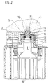
- FIG. 2 shows the area of the armature shaft in a first exemplary embodiment.
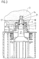
- Figure 3 shows a second embodiment,
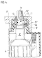
- Figure 4 shows a third embodiment,
- Figure 5 shows a sleeve according to the third embodiment in section and
- Figure 6 shows a plan view of the armature shaft and the sleeve according to the third embodiment.
- a hammer drill has a housing 2, which forms an upper closed grease chamber 3, in which grease-lubricated gear parts, such as a gear wheel 5 arranged on an intermediate shaft, a striking mechanism 6 and other parts, are accommodated.
- an electric motor 8 is arranged below the chamber 3 in the housing 2.
- An armature shaft 9 of the electric motor projects upwards into the chamber 3 of the housing 2.
- the armature shaft 9 is mounted upwards towards the gear parts in a roller bearing 10, which is held in the housing 2 and can also be designed as a plain bearing.
- the gear-side bearing 10 is, as can be seen, for example, from FIG. 2, sealed at the top and bottom by non-grinding sealants, in particular sealing disks 11.
- the armature shaft 9 carries an output pinion 14 at its end projecting into the grease chamber 3.
- the inner ring 12 of the roller bearing 10 lies directly against the armature shaft 9.
- an O-ring 13 is inserted into a groove in the armature shaft.
- a feed spiral 16 is incorporated as a right-handed thread in the right-handed armature shaft 9. The conveying spiral 16 thus engages a part in the inner ring 12 of the roller bearing 10 and ends above a chamber 3 delimiting Housing base 17.
- the housing base 17 forms the lower boundary of the grease chamber in which the grease-lubricated gear parts of the hammer are located.
- An annular gap 19 is formed between the inner ring 12 and the conveyor spiral 16 or between a housing collar 18 and the conveyor spiral 16, in which the lubricant is conveyed upwards from the bearing 10 into the grease chamber 3. Even at high engine speeds, which are between 9,000 and approximately 20,000 revolutions per minute, the conveyor spiral 16 does not lead to the fat being mixed or segregated.
- the second exemplary embodiment according to FIG. 3 is basically constructed in the same way as the first, equivalent components have the same reference numbers or are supplemented by a prime.
- the armature shaft 9 ' is tapered at its end.
- a sleeve 21 is placed, in the outer wall of which a spiral conveyor 16 'is incorporated.
- the sleeve 21 is pressed onto the armature shaft 9 'in the region of a particularly long toothed runout of the output pinion 14. Otherwise, the feed spiral 16 'on the sleeve 21 has the same function as the feed spiral 16 incorporated directly into the armature shaft 9.
- the third exemplary embodiment according to FIGS. 4 to 6 is similar to the first two exemplary embodiments; Identical or similar parts are provided with the same reference numbers or with two prime lines.
- the tapered end of the armature shaft 9 ′′ is pushed into a sleeve 21 ′′ with a sliding fit and sealed by means of an O-ring 13.
- the sleeve 21 is longer than the sleeve 21 and carries a stop collar 22 at its motor end.
- a roller bearing 10 with sealing washers 11 is pressed onto the sleeve 21", the inner ring 12 of which rests on the collar 22.
- the sleeve 21 has an inwardly directed, inwardly hexagonal collar 23 which engages in the driven pinion 14 with six teeth.
- the sleeve 21" is rotatably driven relative to the armature shaft 9 ".
- the sleeve 21 " carries a conveyor helix 16" which extends into the area of the roller bearing 10.
- the conveyor helix ends at the gear end of the sleeve 21 ", which protrudes beyond the housing base 17".
- the sliding fit between the armature shaft 9 and sleeve 21 “allows the motor 8 to be easily pulled out downwards for repair or maintenance purposes and reinserted.
Landscapes
- Engineering & Computer Science (AREA)
- Mechanical Engineering (AREA)
- Connection Of Motors, Electrical Generators, Mechanical Devices, And The Like (AREA)
- Percussive Tools And Related Accessories (AREA)
Applications Claiming Priority (2)
| Application Number | Priority Date | Filing Date | Title |
|---|---|---|---|
| DE4026946A DE4026946A1 (de) | 1990-08-25 | 1990-08-25 | Bohr- und/oder schlaghammer |
| DE4026946 | 1990-08-25 |
Publications (3)
| Publication Number | Publication Date |
|---|---|
| EP0473908A2 true EP0473908A2 (fr) | 1992-03-11 |
| EP0473908A3 EP0473908A3 (en) | 1992-05-20 |
| EP0473908B1 EP0473908B1 (fr) | 1995-03-22 |
Family
ID=6412936
Family Applications (1)
| Application Number | Title | Priority Date | Filing Date |
|---|---|---|---|
| EP91111631A Expired - Lifetime EP0473908B1 (fr) | 1990-08-25 | 1991-07-12 | Marteau à foreuse et/ou à coup |
Country Status (2)
| Country | Link |
|---|---|
| EP (1) | EP0473908B1 (fr) |
| DE (2) | DE4026946A1 (fr) |
Cited By (3)
| Publication number | Priority date | Publication date | Assignee | Title |
|---|---|---|---|---|
| EP0925882A2 (fr) * | 1997-12-01 | 1999-06-30 | Black & Decker Inc. | Outil motorisé avec système de lubrification |
| WO2001055623A1 (fr) * | 2000-01-28 | 2001-08-02 | Robert Bosch Gmbh | Dispositif pour etancheifier un volume |
| CN101520091A (zh) * | 2008-02-28 | 2009-09-02 | 昆山密友实业有限公司 | 流体动压型釜用密封机械 |
Families Citing this family (2)
| Publication number | Priority date | Publication date | Assignee | Title |
|---|---|---|---|---|
| DE10045620A1 (de) * | 2000-09-15 | 2002-04-04 | Bosch Gmbh Robert | Werkzeugmaschine mit einem Raum mit Schmiermittel und einer Druckausgleichseinrichtung des Raums |
| DE10045618A1 (de) * | 2000-09-15 | 2002-04-04 | Bosch Gmbh Robert | Werkzeugmaschine mit einem Raum mit Schmiermittel und einer Druckausgleichseinrichtung des Raums |
Citations (4)
| Publication number | Priority date | Publication date | Assignee | Title |
|---|---|---|---|---|
| DE1915934A1 (de) * | 1969-03-28 | 1970-10-08 | Dornier System Gmbh | Vorrichtung zum Abdichten von Wellen |
| US3937477A (en) * | 1973-12-26 | 1976-02-10 | Borg-Warner Corporation | Mechanical seal system |
| EP0049719A1 (fr) * | 1980-10-09 | 1982-04-21 | John Crane-Houdaille, Inc. | Double joint d'étanchéité à friction réduite |
| DE3235544A1 (de) * | 1982-09-25 | 1984-03-29 | Robert Bosch Gmbh, 7000 Stuttgart | Bohrhammer |
-
1990
- 1990-08-25 DE DE4026946A patent/DE4026946A1/de not_active Withdrawn
-
1991
- 1991-07-12 DE DE59104985T patent/DE59104985D1/de not_active Expired - Lifetime
- 1991-07-12 EP EP91111631A patent/EP0473908B1/fr not_active Expired - Lifetime
Patent Citations (4)
| Publication number | Priority date | Publication date | Assignee | Title |
|---|---|---|---|---|
| DE1915934A1 (de) * | 1969-03-28 | 1970-10-08 | Dornier System Gmbh | Vorrichtung zum Abdichten von Wellen |
| US3937477A (en) * | 1973-12-26 | 1976-02-10 | Borg-Warner Corporation | Mechanical seal system |
| EP0049719A1 (fr) * | 1980-10-09 | 1982-04-21 | John Crane-Houdaille, Inc. | Double joint d'étanchéité à friction réduite |
| DE3235544A1 (de) * | 1982-09-25 | 1984-03-29 | Robert Bosch Gmbh, 7000 Stuttgart | Bohrhammer |
Cited By (6)
| Publication number | Priority date | Publication date | Assignee | Title |
|---|---|---|---|---|
| EP0925882A2 (fr) * | 1997-12-01 | 1999-06-30 | Black & Decker Inc. | Outil motorisé avec système de lubrification |
| EP0925882A3 (fr) * | 1997-12-01 | 2002-01-02 | Black & Decker Inc. | Outil motorisé avec système de lubrification |
| WO2001055623A1 (fr) * | 2000-01-28 | 2001-08-02 | Robert Bosch Gmbh | Dispositif pour etancheifier un volume |
| US6971651B2 (en) | 2000-01-28 | 2005-12-06 | Robert Bosch Gmbh | Device for sealing a space |
| CN100387871C (zh) * | 2000-01-28 | 2008-05-14 | 罗伯特·博施有限公司 | 用于密封一个室的装置 |
| CN101520091A (zh) * | 2008-02-28 | 2009-09-02 | 昆山密友实业有限公司 | 流体动压型釜用密封机械 |
Also Published As
| Publication number | Publication date |
|---|---|
| DE4026946A1 (de) | 1992-02-27 |
| EP0473908A3 (en) | 1992-05-20 |
| EP0473908B1 (fr) | 1995-03-22 |
| DE59104985D1 (de) | 1995-04-27 |
Similar Documents
| Publication | Publication Date | Title |
|---|---|---|
| DE19913658A1 (de) | Getriebe | |
| EP0589337B1 (fr) | Machine outil à main, notamment marteau perforateur | |
| DE1957580A1 (de) | Muehlenantrieb | |
| EP0473908B1 (fr) | Marteau à foreuse et/ou à coup | |
| DE3931116C2 (de) | Antriebseinrichtung für eine Rollenmühle | |
| DE19540391A1 (de) | Bohr- und Meisselgerät | |
| EP0489277A1 (fr) | Machine-outil | |
| EP0041227A2 (fr) | Appareil de coupe pour le dépouillement des animaux de boucherie | |
| DE1155634B (de) | Hilfsgeraeteantrieb an Brennkraftmaschinen | |
| DE3507913C2 (de) | Antrieb, insbesondere Antrieb für Mühlen, vorzugsweise zur Aufmahlung von Kohle | |
| DE3024598A1 (de) | Wellenabdichtung fuer die mischerwellen von betonmischmaschinen | |
| DE3417556A1 (de) | Desintegrator | |
| DE3907316C2 (fr) | ||
| DE2218033A1 (de) | Motorisch angetriebene stemmvorrichtung | |
| DE3733567C1 (de) | Getriebegehaeuse mit einer Lagerung fuer eine mindestens ein Zahnrad tragende Welle | |
| EP0228609B1 (fr) | Pièce à main dentaire à démultiplicateur | |
| DE60200352T2 (de) | Glätt- und Polierkopf für Steinplatten oder sonstige Materialplatten, mit elastisch-schwingungsdämpfenden Elementen | |
| DE700016C (de) | Tellerbrecher | |
| DE60100954T2 (de) | Getriebemotor für Funktionselemente von Fahrzeugen | |
| DE6947529U (de) | Fliehkraftringrollenmuehle. | |
| DE3512605A1 (de) | Ladegeraet-elektrogenerator-einheit fuer fahrzeuge | |
| DE906769C (de) | Antrieb fuer Kreismesserscheren | |
| DE3429108A1 (de) | Mischvorrichtung | |
| DE896898C (de) | Elektrowerkzeug mit einem laengsgeteilten zweiteiligen Gehaeuse | |
| DE482429C (de) | Waelzlagerdichtung fuer Schraemstangen mit durchgehendem Schaft |
Legal Events
| Date | Code | Title | Description |
|---|---|---|---|
| PUAI | Public reference made under article 153(3) epc to a published international application that has entered the european phase |
Free format text: ORIGINAL CODE: 0009012 |
|
| AK | Designated contracting states |
Kind code of ref document: A2 Designated state(s): CH DE FR GB LI |
|
| PUAL | Search report despatched |
Free format text: ORIGINAL CODE: 0009013 |
|
| AK | Designated contracting states |
Kind code of ref document: A3 Designated state(s): CH DE FR GB LI |
|
| 17P | Request for examination filed |
Effective date: 19921017 |
|
| 17Q | First examination report despatched |
Effective date: 19930917 |
|
| GRAA | (expected) grant |
Free format text: ORIGINAL CODE: 0009210 |
|
| AK | Designated contracting states |
Kind code of ref document: B1 Designated state(s): CH DE FR GB LI |
|
| ET | Fr: translation filed | ||
| REF | Corresponds to: |
Ref document number: 59104985 Country of ref document: DE Date of ref document: 19950427 |
|
| GBT | Gb: translation of ep patent filed (gb section 77(6)(a)/1977) |
Effective date: 19950605 |
|
| PLBE | No opposition filed within time limit |
Free format text: ORIGINAL CODE: 0009261 |
|
| STAA | Information on the status of an ep patent application or granted ep patent |
Free format text: STATUS: NO OPPOSITION FILED WITHIN TIME LIMIT |
|
| 26N | No opposition filed | ||
| REG | Reference to a national code |
Ref country code: GB Ref legal event code: IF02 |
|
| PGFP | Annual fee paid to national office [announced via postgrant information from national office to epo] |
Ref country code: CH Payment date: 20100726 Year of fee payment: 20 |
|
| PGFP | Annual fee paid to national office [announced via postgrant information from national office to epo] |
Ref country code: FR Payment date: 20100802 Year of fee payment: 20 |
|
| PGFP | Annual fee paid to national office [announced via postgrant information from national office to epo] |
Ref country code: GB Payment date: 20100726 Year of fee payment: 20 |
|
| PGFP | Annual fee paid to national office [announced via postgrant information from national office to epo] |
Ref country code: DE Payment date: 20100924 Year of fee payment: 20 |
|
| REG | Reference to a national code |
Ref country code: DE Ref legal event code: R071 Ref document number: 59104985 Country of ref document: DE |
|
| REG | Reference to a national code |
Ref country code: DE Ref legal event code: R071 Ref document number: 59104985 Country of ref document: DE |
|
| REG | Reference to a national code |
Ref country code: CH Ref legal event code: PL |
|
| REG | Reference to a national code |
Ref country code: GB Ref legal event code: PE20 Expiry date: 20110711 |
|
| PG25 | Lapsed in a contracting state [announced via postgrant information from national office to epo] |
Ref country code: GB Free format text: LAPSE BECAUSE OF EXPIRATION OF PROTECTION Effective date: 20110711 |
|
| PG25 | Lapsed in a contracting state [announced via postgrant information from national office to epo] |
Ref country code: DE Free format text: LAPSE BECAUSE OF EXPIRATION OF PROTECTION Effective date: 20110713 |