EP0473908A2 - Drill and/or impact hammer - Google Patents
Drill and/or impact hammer Download PDFInfo
- Publication number
- EP0473908A2 EP0473908A2 EP91111631A EP91111631A EP0473908A2 EP 0473908 A2 EP0473908 A2 EP 0473908A2 EP 91111631 A EP91111631 A EP 91111631A EP 91111631 A EP91111631 A EP 91111631A EP 0473908 A2 EP0473908 A2 EP 0473908A2
- Authority
- EP
- European Patent Office
- Prior art keywords
- armature shaft
- sleeve
- hammer
- hammer drill
- bearing
- Prior art date
- Legal status (The legal status is an assumption and is not a legal conclusion. Google has not performed a legal analysis and makes no representation as to the accuracy of the status listed.)
- Granted
Links
Images


Classifications
-
- B—PERFORMING OPERATIONS; TRANSPORTING
- B25—HAND TOOLS; PORTABLE POWER-DRIVEN TOOLS; MANIPULATORS
- B25D—PERCUSSIVE TOOLS
- B25D17/00—Details of, or accessories for, portable power-driven percussive tools
-
- B—PERFORMING OPERATIONS; TRANSPORTING
- B25—HAND TOOLS; PORTABLE POWER-DRIVEN TOOLS; MANIPULATORS
- B25D—PERCUSSIVE TOOLS
- B25D17/00—Details of, or accessories for, portable power-driven percussive tools
- B25D17/26—Lubricating
Definitions
- the invention is based on a hammer drill and / or percussion hammer according to the preamble of claim 1.
- hammers with grease-lubricated gear pairs which are arranged above the electric motor in the position of use, there is a risk of grease escaping into the motor area if there is no sealing, which in particular can lead to an early failure of the hammer when penetrating the brush apparatus.
- grinding seals have been used to seal the armature shaft, e.g. Shaft seals (DE-OS 32 35 544), cover plates or felt rings are used. If these seals wear out and due to the constant stress caused by the lubricant acting on them in the direction of gravity, there is a certain risk of grease entering the motor area during continuous operation.
- the hammer and / or percussion hammer according to the invention with the characterizing features of claim 1 has the advantage that lubricant of any consistency is constantly promoted away from the armature shaft bearing in the grease space of the transmission.
- the conveyor spiral works completely wear-free, without power consumption and without Heat development.
- the conveying helix conveys lubricant from the gearbox-side anchor bearing located below the grease level of the hammer back into the grease space of the gearbox, which is not possible, for example, with centrifugal disks, which in this case would only whisk and separate the grease.
- the conveyor helix has the further advantage that neither the surface of the bore in the housing nor the outer diameter of the conveyor helix have to be subjected to high surface quality requirements, as is necessary with grinding elastomer seals.
- the gear-side roller bearing is additionally sealed by non-grinding sealants such as sealing washers. These keep the engine compartment free of lubricants even when the engine is at a standstill.
- the conveyor spiral has its best effect if it reaches as far as or even into the gearbox-side roller bearing.
- a conveying effect is brought about by an annular gap formed by the housing around the conveying helix.
- a sealing ring in particular an O-ring between the armature shaft and roller bearing, prevents grease from penetrating at this point and enables a sliding seat for easier dismantling of the motor in the event of a repair.
- the conveyor spiral can either be incorporated directly into the armature shaft or into a sleeve placed on the armature shaft.
- a sleeve has the advantage that the armature shaft does not need to be changed and the rolling bearing can be pressed directly onto the sleeve.
- the armature shaft can in turn be seated in the sleeve with a sliding seat and an O-ring seal. This simplifies the dismantling of the motor in the event of a repair and has the further advantage that when the hammer is dismantled, no worn sealing elements have to be replaced or run-in shafts have to be reworked.
- FIG. 1 shows a partial section through a hammer drill and / or hammer.
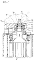
- FIG. 2 shows the area of the armature shaft in a first exemplary embodiment.
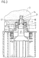
- Figure 3 shows a second embodiment,
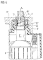
- Figure 4 shows a third embodiment,
- Figure 5 shows a sleeve according to the third embodiment in section and
- Figure 6 shows a plan view of the armature shaft and the sleeve according to the third embodiment.
- a hammer drill has a housing 2, which forms an upper closed grease chamber 3, in which grease-lubricated gear parts, such as a gear wheel 5 arranged on an intermediate shaft, a striking mechanism 6 and other parts, are accommodated.
- an electric motor 8 is arranged below the chamber 3 in the housing 2.
- An armature shaft 9 of the electric motor projects upwards into the chamber 3 of the housing 2.
- the armature shaft 9 is mounted upwards towards the gear parts in a roller bearing 10, which is held in the housing 2 and can also be designed as a plain bearing.
- the gear-side bearing 10 is, as can be seen, for example, from FIG. 2, sealed at the top and bottom by non-grinding sealants, in particular sealing disks 11.
- the armature shaft 9 carries an output pinion 14 at its end projecting into the grease chamber 3.
- the inner ring 12 of the roller bearing 10 lies directly against the armature shaft 9.
- an O-ring 13 is inserted into a groove in the armature shaft.
- a feed spiral 16 is incorporated as a right-handed thread in the right-handed armature shaft 9. The conveying spiral 16 thus engages a part in the inner ring 12 of the roller bearing 10 and ends above a chamber 3 delimiting Housing base 17.
- the housing base 17 forms the lower boundary of the grease chamber in which the grease-lubricated gear parts of the hammer are located.
- An annular gap 19 is formed between the inner ring 12 and the conveyor spiral 16 or between a housing collar 18 and the conveyor spiral 16, in which the lubricant is conveyed upwards from the bearing 10 into the grease chamber 3. Even at high engine speeds, which are between 9,000 and approximately 20,000 revolutions per minute, the conveyor spiral 16 does not lead to the fat being mixed or segregated.
- the second exemplary embodiment according to FIG. 3 is basically constructed in the same way as the first, equivalent components have the same reference numbers or are supplemented by a prime.
- the armature shaft 9 ' is tapered at its end.
- a sleeve 21 is placed, in the outer wall of which a spiral conveyor 16 'is incorporated.
- the sleeve 21 is pressed onto the armature shaft 9 'in the region of a particularly long toothed runout of the output pinion 14. Otherwise, the feed spiral 16 'on the sleeve 21 has the same function as the feed spiral 16 incorporated directly into the armature shaft 9.
- the third exemplary embodiment according to FIGS. 4 to 6 is similar to the first two exemplary embodiments; Identical or similar parts are provided with the same reference numbers or with two prime lines.
- the tapered end of the armature shaft 9 ′′ is pushed into a sleeve 21 ′′ with a sliding fit and sealed by means of an O-ring 13.
- the sleeve 21 is longer than the sleeve 21 and carries a stop collar 22 at its motor end.
- a roller bearing 10 with sealing washers 11 is pressed onto the sleeve 21", the inner ring 12 of which rests on the collar 22.
- the sleeve 21 has an inwardly directed, inwardly hexagonal collar 23 which engages in the driven pinion 14 with six teeth.
- the sleeve 21" is rotatably driven relative to the armature shaft 9 ".
- the sleeve 21 " carries a conveyor helix 16" which extends into the area of the roller bearing 10.
- the conveyor helix ends at the gear end of the sleeve 21 ", which protrudes beyond the housing base 17".
- the sliding fit between the armature shaft 9 and sleeve 21 “allows the motor 8 to be easily pulled out downwards for repair or maintenance purposes and reinserted.
Abstract
Description
Die Erfindung geht aus von einem Bohr- und/oder Schlaghammer nach dem Oberbegriff des Anspruchs 1. Bei Hämmern mit fettgeschmierten Zahnradpaarungen, die in Gebrauchslage oberhalb des Elektromotors angeordnet sind, besteht bei mangelnder Abdichtung die Gefahr eines Austritts von Fett in den Motorbereich, was insbesondere beim Eindringen in den Bürstenapparat zu einem Frühausfall des Hammers führen kann. Zur Abdichtung der Ankerwelle wurden bisher schleifende Dichtungen, z.B. Wellendichtringe (DE-OS 32 35 544), Abdeckscheiben oder Filzringe verwendet. Bei Verschleiß dieser Dichtungen und durch die ständige Beanspruchung durch das in Schwerkraftrichtung auf sie einwirkende Schmiermittel besteht im Dauerbetrieb eine gewisse Gefahr des Fetteintritts in den Motorbereich.The invention is based on a hammer drill and / or percussion hammer according to the preamble of
Der erfindungsgemäße Bohr- und/oder Schlaghammer mit den kennzeichnenden Merkmalen des Anspruchs 1 hat demgegenüber den Vorteil, daß Schmiermittel jeglicher Konsistenz ständig von dem Ankerwellenlager weg in den Fettraum des Getriebes gefördert wird. Die Förderwendel funktioniert völlig verschleißfrei, ohne Leistungsaufnahme und ohne Wärmeentwicklung. Die Förderwendel fördert Schmiermittel von dem unterhalb des Fettniveaus des Hammers angeordneten getriebeseitigen Ankerlager in den Fettraum des Getriebes zurück, was zum Beispiel mit Schleuderscheiben, die in diesem Fall das Fett nur verquirlen und entmischen würden, nicht möglich ist. Die Förderwendel hat den weiteren Vorteil, daß weder an die Oberfläche der Bohrung im Gehäuse noch an den Außendurchmesser der Förderwendel hohe Anforderungen an die Oberflächenqualität gestellt werden müssen, wie dies bei schleifenden Elastomerdichtungen nötig ist.The hammer and / or percussion hammer according to the invention with the characterizing features of
Durch die in den abhängigen Ansprüchen aufgeführten Maßnahmen sind vorteilhafte Weiterbildungen und Verbesserungen des im Anspruch 1 angegebenen Bohr- und/oder Schlaghammers möglich. Besonders vorteilhaft ist es, wenn das getriebeseitige Wälzlager durch nichtschleifende Dichtmittel wie Dichtscheiben zusätzlich abgedichtet ist. Diese halten auch bei Stillstand des Motors den Motorraum von Schmiermitteln frei. Die Förderwendel entfaltet ihre beste Wirkung, wenn sie bis an oder sogar in das getriebeseitige Wälzlager hinein heranreicht. Durch einen um die Förderwendel herum von dem Gehäuse gebildeten Ringspalt wird eine Förderwirkung bewirkt. Ein Dichtring, insbesondere O-Ring zwischen Ankerwelle und Wälzlager verhindert einen Fettdurchtritt an dieser Stelle und ermöglicht einen Schiebesitz zur leichteren Demontage des Motors im Reparaturfall. Die Förderwendel kann entweder direkt in die Ankerwelle oder in eine auf die Ankerwelle aufgesetzte Hülse eingearbeitet sein. Eine solche Hülse hat den Vorteil, daß die Ankerwelle nicht geändert zu werden braucht und das Wälzlager direkt auf die Hülse aufgepreßt werden kann. Die Ankerwelle kann dann ihrerseits wiederum mit einem Schiebesitz und einer O-Ringdichtung in der Hülse sitzen. Dies erleichert die Demontage des Motors im Reparaturfall und hat den weiteren Vorteil, daß bei der Demontage des Hammers keine abgenutzten Dichtelemente ausgetauscht oder eingelaufene Wellen nachgearbeitet werden müssen.The measures listed in the dependent claims allow advantageous developments and improvements of the hammer drill and / or percussion hammer specified in
Drei Ausführungsbeispiele der Erfindung sind in der Zeichnung dargestellt und in der nachfolgenden Beschreibung näher erläutert. Figur 1 zeigt einen Teilschnitt durch einen Bohr- und/oder Schlaghammer. Figur 2 zeigt in einem ersten Ausführungsbeispiel den Bereich der Ankerwelle. Figur 3 zeigt ein zweites Ausführungsbeispiel, Figur 4 zeigt ein drittes Ausführungsbeispiel, Figur 5 zeigt eine Hülse gemäß dem dritten Ausführungsbeispiel im Schnitt und Figur 6 zeigt eine Draufsicht auf die Ankerwelle und die Hülse gemäß dem dritten Ausführungsbeispiel.Three embodiments of the invention are shown in the drawing and explained in more detail in the following description. Figure 1 shows a partial section through a hammer drill and / or hammer. FIG. 2 shows the area of the armature shaft in a first exemplary embodiment. Figure 3 shows a second embodiment, Figure 4 shows a third embodiment, Figure 5 shows a sleeve according to the third embodiment in section and Figure 6 shows a plan view of the armature shaft and the sleeve according to the third embodiment.
Ein Bohrhammer weist ein Gehäuse 2 auf, das eine obere geschlossene Fettkammer 3 bildet, in der fettgeschmierte Getriebeteile, wie ein auf einer Zwischenwelle angeordnetes Getriebezahnrad 5, ein Schlagwerk 6 und weitere Teile untergebracht sind. In der üblichen in Figur 1 gezeigten Gebrauchslage des Hammers ist unterhalb der Kammer 3 in dem Gehäuse 2 ein Elektromotor 8 angeordnet. Eine Ankerwelle 9 des Elektromotors ragt nach oben in die Kammer 3 des Gehäuses 2 hinein. Die Ankerwelle 9 ist nach oben zu den Getriebeteilen hin in einem Wälzlager 10 gelagert, das in dem Gehäuse 2 gehalten ist und auch als Gleitlager ausgebildet sein kann. Das getriebeseitige Lager 10 ist, wie zum Beispiel aus Figur 2 ersichtlich ist, oben und unten durch nichtschleifende Dichtmittel, insbesondere Dichtscheiben 11 abgedichtet. Die Ankerwelle 9 trägt an ihrem in die Fettkammer 3 hineinragenden Ende ein Abtriebsritzel 14. Der Innenring 12 des Wälzlagers 10 liegt direkt an der Ankerwelle 9 an. Zur Abdichtung der Ankerwelle 9 gegenüber dem Innenring 12 ist in eine Nut der Ankerwelle ein O-Ring 13 eingelegt. Zwischen dem O-Ring 13 und dem Abtriebsritzel 14 ist in die rechtsdrehende Ankerwelle 9 eine Förderwendel 16 als rechtsdrehendes Gewinde eingearbeitet. Die Förderwendel 16 greift damit ein stückweit in den Innenring 12 des Wälzlagers 10 ein und endet oberhalb eines die Kammer 3 begrenzenden Gehäusebodens 17. Der Gehäuseboden 17 bildet die untere Begrenzung des Fettraums, in dem sich die fettgeschmierten Getriebeteile des Hammers befinden. Zwischen dem Innenring 12 und der Förderwendel 16 bzw. zwischen einem Gehäusekragen 18 und der Förderwendel 16 ist ein Ringspalt 19 ausgebildet, in dem das Schmiermittel aufwärts von Lager 10 weg in die Fettkammer 3 befördert wird. Die Förderwendel 16 führt auch bei hohen Motordrehzahlen, die zwischen 9000 bis annähernd 20000 Umdrehungen pro Minute liegen, nicht zu einem Verquirlen oder Entmischen des Fettes. Durch entsprechende Auslegung des Ringspalts 19, der Form und Steigung der Förderwendel 16 und des vom Drehsinn der Ankerwelle abhängigen Steigungssinns der Förderwendel 16 ergibt sich für alle gebräuchlichen Fettkonsistenzen eine sehr gute Rückförder- und damit Dichtwirkung an der Ankerwelle.A hammer drill has a
Das zweite Ausführungsbeispiel nach der Figur 3 ist grundsätzlich in gleicher Weise aufgebaut wie das erste, gleichwertige Bauteile tragen gleiche bzw. durch einen Hochstrich ergänzte Bezugsziffern. Die Ankerwelle 9' ist an ihrem Ende verjüngt. Auf das verjüngte Ende ist eine Hülse 21 aufgesetzt, in deren Außenwand eine Förderwendel 16' eingearbeitet ist. Die Hülse 21 ist im Bereich eines besonders langen Verzahnungsauslaufs des Abtriebsritzels 14 auf die Ankerwelle 9' aufgepreßt. Im übrigen hat die Förderwendel 16' auf der Hülse 21 die gleiche Funktion wie die direkt in die Ankerwelle 9 eingearbeitete Förderwendel 16.The second exemplary embodiment according to FIG. 3 is basically constructed in the same way as the first, equivalent components have the same reference numbers or are supplemented by a prime. The armature shaft 9 'is tapered at its end. On the tapered end, a
Auch das dritte Ausführungsbeispiel gemäß den Figuren 4 bis 6 ähnelt den ersten beiden Ausführungsbeispielen; gleiche oder ähnliche Teile sind mit gleichen oder durch zwei Hochstriche ergänzte Bezugszahlen versehen. Das verjüngte Ende der Ankerwelle 9" ist mit Schiebesitz in eine Hülse 21" eingeschoben und mittels eines O-Rings 13 diesem gegenüber abgedichtet. Die Hülse 21" ist länger als die Hülse 21 und trägt an ihrem motorseitigen Ende einen Anschlagbund 22. Auf die Hülse 21" aufgepreßt ist ein Wälzlager 10 mit Dichtscheiben 11, dessen Innenring 12 an dem Bund 22 anliegt. Am getriebeseitigen Ende hat die Hülse 21" einen nach innen gerichteten, innen sechskantigen Bund 23, der in das Abtriebsritzel 14 mit sechs Zähnen formschlüssig eingreift. Damit ist die Drehmitnahme der Hülse 21" gegenüber der Ankerwelle 9" gewährleistet. Zwischen dem Bund 23 und den Zähnen des Abtriebsritzels 14 ist soviel Spiel, daß eine leichte Montage möglich ist. Die Drehmitnahme kann natürlich auch in anderer formschlüssiger, spielbehafteter Weise ausgeführt sein. An der Außenseite trägt die Hülse 21" eine bis in den Bereich des Wälzlagers 10 hineinreichende Förderwendel 16". Die Förderwendel endet am getriebeseitigen Ende der Hülse 21", das über den Gehäuseboden 17" hinausragt. Durch den Schiebesitz zwischen Ankerwelle 9 und Hülse 21" kann der Motor 8 zur Reparatur oder zu Wartungszwecken leicht nach unten herausgezogen und wieder eingesetzt werden.The third exemplary embodiment according to FIGS. 4 to 6 is similar to the first two exemplary embodiments; Identical or similar parts are provided with the same reference numbers or with two prime lines. The tapered end of the
Claims (10)
Applications Claiming Priority (2)
| Application Number | Priority Date | Filing Date | Title |
|---|---|---|---|
| DE4026946 | 1990-08-25 | ||
| DE4026946A DE4026946A1 (en) | 1990-08-25 | 1990-08-25 | DRILL AND / OR SLOPE |
Publications (3)
| Publication Number | Publication Date |
|---|---|
| EP0473908A2 true EP0473908A2 (en) | 1992-03-11 |
| EP0473908A3 EP0473908A3 (en) | 1992-05-20 |
| EP0473908B1 EP0473908B1 (en) | 1995-03-22 |
Family
ID=6412936
Family Applications (1)
| Application Number | Title | Priority Date | Filing Date |
|---|---|---|---|
| EP91111631A Expired - Lifetime EP0473908B1 (en) | 1990-08-25 | 1991-07-12 | Drill and/or impact hammer |
Country Status (2)
| Country | Link |
|---|---|
| EP (1) | EP0473908B1 (en) |
| DE (2) | DE4026946A1 (en) |
Cited By (3)
| Publication number | Priority date | Publication date | Assignee | Title |
|---|---|---|---|---|
| EP0925882A2 (en) * | 1997-12-01 | 1999-06-30 | Black & Decker Inc. | Power tool with lubricating system |
| WO2001055623A1 (en) * | 2000-01-28 | 2001-08-02 | Robert Bosch Gmbh | Device for sealing a space |
| CN101520091A (en) * | 2008-02-28 | 2009-09-02 | 昆山密友实业有限公司 | Hydrodynamic pressure type sealing machine of kettle |
Families Citing this family (2)
| Publication number | Priority date | Publication date | Assignee | Title |
|---|---|---|---|---|
| DE10045618A1 (en) * | 2000-09-15 | 2002-04-04 | Bosch Gmbh Robert | Machine tool with a room with lubricant and a pressure compensation device of the room |
| DE10045620A1 (en) * | 2000-09-15 | 2002-04-04 | Bosch Gmbh Robert | Machine tool with a room with lubricant and a pressure compensation device of the room |
Citations (4)
| Publication number | Priority date | Publication date | Assignee | Title |
|---|---|---|---|---|
| DE1915934A1 (en) * | 1969-03-28 | 1970-10-08 | Dornier System Gmbh | Device for sealing shafts |
| US3937477A (en) * | 1973-12-26 | 1976-02-10 | Borg-Warner Corporation | Mechanical seal system |
| EP0049719A1 (en) * | 1980-10-09 | 1982-04-21 | John Crane-Houdaille, Inc. | Low energy tandem seal |
| DE3235544A1 (en) * | 1982-09-25 | 1984-03-29 | Robert Bosch Gmbh, 7000 Stuttgart | Drill hammer |
-
1990
- 1990-08-25 DE DE4026946A patent/DE4026946A1/en not_active Withdrawn
-
1991
- 1991-07-12 DE DE59104985T patent/DE59104985D1/en not_active Expired - Lifetime
- 1991-07-12 EP EP91111631A patent/EP0473908B1/en not_active Expired - Lifetime
Patent Citations (4)
| Publication number | Priority date | Publication date | Assignee | Title |
|---|---|---|---|---|
| DE1915934A1 (en) * | 1969-03-28 | 1970-10-08 | Dornier System Gmbh | Device for sealing shafts |
| US3937477A (en) * | 1973-12-26 | 1976-02-10 | Borg-Warner Corporation | Mechanical seal system |
| EP0049719A1 (en) * | 1980-10-09 | 1982-04-21 | John Crane-Houdaille, Inc. | Low energy tandem seal |
| DE3235544A1 (en) * | 1982-09-25 | 1984-03-29 | Robert Bosch Gmbh, 7000 Stuttgart | Drill hammer |
Cited By (6)
| Publication number | Priority date | Publication date | Assignee | Title |
|---|---|---|---|---|
| EP0925882A2 (en) * | 1997-12-01 | 1999-06-30 | Black & Decker Inc. | Power tool with lubricating system |
| EP0925882A3 (en) * | 1997-12-01 | 2002-01-02 | Black & Decker Inc. | Power tool with lubricating system |
| WO2001055623A1 (en) * | 2000-01-28 | 2001-08-02 | Robert Bosch Gmbh | Device for sealing a space |
| US6971651B2 (en) | 2000-01-28 | 2005-12-06 | Robert Bosch Gmbh | Device for sealing a space |
| CN100387871C (en) * | 2000-01-28 | 2008-05-14 | 罗伯特·博施有限公司 | Device for sealing a space |
| CN101520091A (en) * | 2008-02-28 | 2009-09-02 | 昆山密友实业有限公司 | Hydrodynamic pressure type sealing machine of kettle |
Also Published As
| Publication number | Publication date |
|---|---|
| EP0473908B1 (en) | 1995-03-22 |
| DE59104985D1 (en) | 1995-04-27 |
| DE4026946A1 (en) | 1992-02-27 |
| EP0473908A3 (en) | 1992-05-20 |
Similar Documents
| Publication | Publication Date | Title |
|---|---|---|
| DE19913658A1 (en) | Mixer | |
| DE1957580A1 (en) | Mill drive | |
| EP0063257B1 (en) | Mixer with annular vat | |
| EP0473908B1 (en) | Drill and/or impact hammer | |
| DE19540391A1 (en) | Drilling and chiseling device | |
| EP0489277A1 (en) | Powered hand tool | |
| EP0041227A2 (en) | Cutting device for flaying slaughtered animals | |
| DE1155634B (en) | Auxiliary device drive on internal combustion engines | |
| DE3507913C2 (en) | Drive, in particular drive for mills, preferably for grinding coal | |
| DE3024598A1 (en) | Seal assembly for shaft of concrete mixer - where profiled ring fixed to shaft forms labyrinthine gap with hard polymer bearing shell | |
| DE3907316C2 (en) | ||
| DE2218033A1 (en) | MOTOR-DRIVEN CHISING DEVICE | |
| DE3733567C1 (en) | Gear housing with a bearing for a shaft carrying at least one gear | |
| EP0228609B1 (en) | Dental handpiece with reducing gear | |
| DE60200352T2 (en) | Smoothing and polishing head for stone slabs or other material plates, with elastic-vibration-damping elements | |
| DE2635379A1 (en) | HOUSING FOR ELECTRIC TOOLS | |
| DE700016C (en) | Plate crusher | |
| DE60100954T2 (en) | Gear motor for functional elements of vehicles | |
| DE6947529U (en) | CENTRIFUGAL RING ROLLER MILL. | |
| DE3512605A1 (en) | CHARGER ELECTRIC GENERATOR UNIT FOR VEHICLES | |
| DE906769C (en) | Drive for circular knife shears | |
| DE3429108A1 (en) | MIXING DEVICE | |
| DE896898C (en) | Power tool with a longitudinally divided two-part housing | |
| DE482429C (en) | Roller bearing seal for Schraemstangen with continuous shaft | |
| DE975402C (en) | Speed reduction gear for Koller gears |
Legal Events
| Date | Code | Title | Description |
|---|---|---|---|
| PUAI | Public reference made under article 153(3) epc to a published international application that has entered the european phase |
Free format text: ORIGINAL CODE: 0009012 |
|
| AK | Designated contracting states |
Kind code of ref document: A2 Designated state(s): CH DE FR GB LI |
|
| PUAL | Search report despatched |
Free format text: ORIGINAL CODE: 0009013 |
|
| AK | Designated contracting states |
Kind code of ref document: A3 Designated state(s): CH DE FR GB LI |
|
| 17P | Request for examination filed |
Effective date: 19921017 |
|
| 17Q | First examination report despatched |
Effective date: 19930917 |
|
| GRAA | (expected) grant |
Free format text: ORIGINAL CODE: 0009210 |
|
| AK | Designated contracting states |
Kind code of ref document: B1 Designated state(s): CH DE FR GB LI |
|
| ET | Fr: translation filed | ||
| REF | Corresponds to: |
Ref document number: 59104985 Country of ref document: DE Date of ref document: 19950427 |
|
| GBT | Gb: translation of ep patent filed (gb section 77(6)(a)/1977) |
Effective date: 19950605 |
|
| PLBE | No opposition filed within time limit |
Free format text: ORIGINAL CODE: 0009261 |
|
| STAA | Information on the status of an ep patent application or granted ep patent |
Free format text: STATUS: NO OPPOSITION FILED WITHIN TIME LIMIT |
|
| 26N | No opposition filed | ||
| REG | Reference to a national code |
Ref country code: GB Ref legal event code: IF02 |
|
| PGFP | Annual fee paid to national office [announced via postgrant information from national office to epo] |
Ref country code: CH Payment date: 20100726 Year of fee payment: 20 |
|
| PGFP | Annual fee paid to national office [announced via postgrant information from national office to epo] |
Ref country code: FR Payment date: 20100802 Year of fee payment: 20 |
|
| PGFP | Annual fee paid to national office [announced via postgrant information from national office to epo] |
Ref country code: GB Payment date: 20100726 Year of fee payment: 20 |
|
| PGFP | Annual fee paid to national office [announced via postgrant information from national office to epo] |
Ref country code: DE Payment date: 20100924 Year of fee payment: 20 |
|
| REG | Reference to a national code |
Ref country code: DE Ref legal event code: R071 Ref document number: 59104985 Country of ref document: DE |
|
| REG | Reference to a national code |
Ref country code: DE Ref legal event code: R071 Ref document number: 59104985 Country of ref document: DE |
|
| REG | Reference to a national code |
Ref country code: CH Ref legal event code: PL |
|
| REG | Reference to a national code |
Ref country code: GB Ref legal event code: PE20 Expiry date: 20110711 |
|
| PG25 | Lapsed in a contracting state [announced via postgrant information from national office to epo] |
Ref country code: GB Free format text: LAPSE BECAUSE OF EXPIRATION OF PROTECTION Effective date: 20110711 |
|
| PG25 | Lapsed in a contracting state [announced via postgrant information from national office to epo] |
Ref country code: DE Free format text: LAPSE BECAUSE OF EXPIRATION OF PROTECTION Effective date: 20110713 |