EP0473697B1 - Catheter with low-friction distal segment - Google Patents
Catheter with low-friction distal segment Download PDFInfo
- Publication number
- EP0473697B1 EP0473697B1 EP90908859A EP90908859A EP0473697B1 EP 0473697 B1 EP0473697 B1 EP 0473697B1 EP 90908859 A EP90908859 A EP 90908859A EP 90908859 A EP90908859 A EP 90908859A EP 0473697 B1 EP0473697 B1 EP 0473697B1
- Authority
- EP
- European Patent Office
- Prior art keywords
- catheter
- distal
- segment
- guidewire
- tube
- Prior art date
- Legal status (The legal status is an assumption and is not a legal conclusion. Google has not performed a legal analysis and makes no representation as to the accuracy of the status listed.)
- Expired - Lifetime
Links
- 229920000642 polymer Polymers 0.000 claims abstract description 20
- 230000037361 pathway Effects 0.000 claims abstract description 14
- 239000000463 material Substances 0.000 claims description 49
- 239000002245 particle Substances 0.000 claims description 30
- BASFCYQUMIYNBI-UHFFFAOYSA-N platinum Chemical compound [Pt] BASFCYQUMIYNBI-UHFFFAOYSA-N 0.000 claims description 14
- 238000004804 winding Methods 0.000 claims description 12
- OKTJSMMVPCPJKN-UHFFFAOYSA-N Carbon Chemical compound [C] OKTJSMMVPCPJKN-UHFFFAOYSA-N 0.000 claims description 8
- 239000011230 binding agent Substances 0.000 claims description 8
- 229910052799 carbon Inorganic materials 0.000 claims description 7
- 229910052697 platinum Inorganic materials 0.000 claims description 7
- 239000003831 antifriction material Substances 0.000 claims description 6
- 229920001903 high density polyethylene Polymers 0.000 claims description 5
- 229920001684 low density polyethylene Polymers 0.000 claims description 5
- 239000004814 polyurethane Substances 0.000 claims description 5
- 230000002250 progressing effect Effects 0.000 claims description 5
- PCHJSUWPFVWCPO-UHFFFAOYSA-N gold Chemical compound [Au] PCHJSUWPFVWCPO-UHFFFAOYSA-N 0.000 claims description 4
- 239000010931 gold Substances 0.000 claims description 4
- 229910052737 gold Inorganic materials 0.000 claims description 4
- 239000004700 high-density polyethylene Substances 0.000 claims description 4
- 239000004702 low-density polyethylene Substances 0.000 claims description 4
- -1 polypropylene Polymers 0.000 claims description 4
- 229920002635 polyurethane Polymers 0.000 claims description 4
- 239000004677 Nylon Substances 0.000 claims description 3
- 239000004743 Polypropylene Substances 0.000 claims description 3
- 238000004132 cross linking Methods 0.000 claims description 3
- 229920001778 nylon Polymers 0.000 claims description 3
- 229920001155 polypropylene Polymers 0.000 claims description 3
- WFKWXMTUELFFGS-UHFFFAOYSA-N tungsten Chemical compound [W] WFKWXMTUELFFGS-UHFFFAOYSA-N 0.000 claims description 2
- 229920000271 Kevlar® Polymers 0.000 claims 1
- 239000004809 Teflon Substances 0.000 claims 1
- 229920006362 Teflon® Polymers 0.000 claims 1
- NIXOWILDQLNWCW-UHFFFAOYSA-N acrylic acid group Chemical group C(C=C)(=O)O NIXOWILDQLNWCW-UHFFFAOYSA-N 0.000 claims 1
- 229910045601 alloy Inorganic materials 0.000 claims 1
- 239000000956 alloy Substances 0.000 claims 1
- 230000001419 dependent effect Effects 0.000 claims 1
- 239000004761 kevlar Substances 0.000 claims 1
- 239000002861 polymer material Substances 0.000 claims 1
- 229910052721 tungsten Inorganic materials 0.000 claims 1
- 239000010937 tungsten Substances 0.000 claims 1
- 238000000576 coating method Methods 0.000 description 24
- 239000011248 coating agent Substances 0.000 description 23
- 238000000034 method Methods 0.000 description 22
- 210000001519 tissue Anatomy 0.000 description 17
- 238000012360 testing method Methods 0.000 description 16
- 238000010276 construction Methods 0.000 description 12
- 230000017531 blood circulation Effects 0.000 description 7
- 239000000203 mixture Substances 0.000 description 7
- 238000005452 bending Methods 0.000 description 6
- 238000001125 extrusion Methods 0.000 description 6
- 239000003795 chemical substances by application Substances 0.000 description 5
- 239000011324 bead Substances 0.000 description 4
- 230000008901 benefit Effects 0.000 description 4
- 238000009954 braiding Methods 0.000 description 4
- 210000004556 brain Anatomy 0.000 description 4
- 239000012530 fluid Substances 0.000 description 4
- 239000002184 metal Substances 0.000 description 4
- 229910052751 metal Inorganic materials 0.000 description 4
- 239000002002 slurry Substances 0.000 description 4
- 230000007704 transition Effects 0.000 description 4
- 210000000709 aorta Anatomy 0.000 description 3
- 239000007767 bonding agent Substances 0.000 description 3
- 229920005570 flexible polymer Polymers 0.000 description 3
- 229940063583 high-density polyethylene Drugs 0.000 description 3
- 238000009941 weaving Methods 0.000 description 3
- 238000000418 atomic force spectrum Methods 0.000 description 2
- 210000004204 blood vessel Anatomy 0.000 description 2
- 239000003431 cross linking reagent Substances 0.000 description 2
- 201000010099 disease Diseases 0.000 description 2
- 208000037265 diseases, disorders, signs and symptoms Diseases 0.000 description 2
- 239000003814 drug Substances 0.000 description 2
- 238000001035 drying Methods 0.000 description 2
- 230000000694 effects Effects 0.000 description 2
- 239000010410 layer Substances 0.000 description 2
- 238000004519 manufacturing process Methods 0.000 description 2
- 239000002923 metal particle Substances 0.000 description 2
- 238000012986 modification Methods 0.000 description 2
- 230000004048 modification Effects 0.000 description 2
- 230000008569 process Effects 0.000 description 2
- 229920005989 resin Polymers 0.000 description 2
- 239000011347 resin Substances 0.000 description 2
- 239000002356 single layer Substances 0.000 description 2
- 239000000126 substance Substances 0.000 description 2
- 238000012956 testing procedure Methods 0.000 description 2
- 229940124597 therapeutic agent Drugs 0.000 description 2
- KXGFMDJXCMQABM-UHFFFAOYSA-N 2-methoxy-6-methylphenol Chemical compound [CH]OC1=CC=CC([CH])=C1O KXGFMDJXCMQABM-UHFFFAOYSA-N 0.000 description 1
- 208000022211 Arteriovenous Malformations Diseases 0.000 description 1
- 102000008186 Collagen Human genes 0.000 description 1
- 108010035532 Collagen Proteins 0.000 description 1
- 206010028980 Neoplasm Diseases 0.000 description 1
- 239000004698 Polyethylene Substances 0.000 description 1
- 239000004372 Polyvinyl alcohol Substances 0.000 description 1
- FAPWRFPIFSIZLT-UHFFFAOYSA-M Sodium chloride Chemical compound [Na+].[Cl-] FAPWRFPIFSIZLT-UHFFFAOYSA-M 0.000 description 1
- BOTDANWDWHJENH-UHFFFAOYSA-N Tetraethyl orthosilicate Chemical compound CCO[Si](OCC)(OCC)OCC BOTDANWDWHJENH-UHFFFAOYSA-N 0.000 description 1
- WYTGDNHDOZPMIW-RCBQFDQVSA-N alstonine Natural products C1=CC2=C3C=CC=CC3=NC2=C2N1C[C@H]1[C@H](C)OC=C(C(=O)OC)[C@H]1C2 WYTGDNHDOZPMIW-RCBQFDQVSA-N 0.000 description 1
- 238000004873 anchoring Methods 0.000 description 1
- 238000002583 angiography Methods 0.000 description 1
- 239000002246 antineoplastic agent Substances 0.000 description 1
- 229940041181 antineoplastic drug Drugs 0.000 description 1
- 238000013459 approach Methods 0.000 description 1
- 230000005744 arteriovenous malformation Effects 0.000 description 1
- 210000005013 brain tissue Anatomy 0.000 description 1
- 230000000747 cardiac effect Effects 0.000 description 1
- 239000003054 catalyst Substances 0.000 description 1
- 230000008859 change Effects 0.000 description 1
- 229920001436 collagen Polymers 0.000 description 1
- 229920001577 copolymer Polymers 0.000 description 1
- 230000003247 decreasing effect Effects 0.000 description 1
- 239000000032 diagnostic agent Substances 0.000 description 1
- 229940039227 diagnostic agent Drugs 0.000 description 1
- 238000007598 dipping method Methods 0.000 description 1
- 230000003073 embolic effect Effects 0.000 description 1
- 238000005516 engineering process Methods 0.000 description 1
- 239000000835 fiber Substances 0.000 description 1
- 238000007429 general method Methods 0.000 description 1
- 229910002804 graphite Inorganic materials 0.000 description 1
- 239000010439 graphite Substances 0.000 description 1
- 238000010438 heat treatment Methods 0.000 description 1
- 239000007788 liquid Substances 0.000 description 1
- 210000004185 liver Anatomy 0.000 description 1
- 239000002831 pharmacologic agent Substances 0.000 description 1
- 229920001568 phenolic resin Polymers 0.000 description 1
- 239000005011 phenolic resin Substances 0.000 description 1
- 238000009832 plasma treatment Methods 0.000 description 1
- 238000007747 plating Methods 0.000 description 1
- 229920000573 polyethylene Polymers 0.000 description 1
- 239000005056 polyisocyanate Substances 0.000 description 1
- 229920001228 polyisocyanate Polymers 0.000 description 1
- 229920000098 polyolefin Polymers 0.000 description 1
- 229920001296 polysiloxane Polymers 0.000 description 1
- 229920005749 polyurethane resin Polymers 0.000 description 1
- 229920002451 polyvinyl alcohol Polymers 0.000 description 1
- 238000012545 processing Methods 0.000 description 1
- 238000009877 rendering Methods 0.000 description 1
- 239000002210 silicon-based material Substances 0.000 description 1
- 239000011780 sodium chloride Substances 0.000 description 1
- 210000004872 soft tissue Anatomy 0.000 description 1
- 239000002904 solvent Substances 0.000 description 1
- 238000005507 spraying Methods 0.000 description 1
- 238000004544 sputter deposition Methods 0.000 description 1
- 229910001220 stainless steel Inorganic materials 0.000 description 1
- 239000010935 stainless steel Substances 0.000 description 1
- 239000000725 suspension Substances 0.000 description 1
- 238000009864 tensile test Methods 0.000 description 1
- 238000004154 testing of material Methods 0.000 description 1
- 238000011144 upstream manufacturing Methods 0.000 description 1
- 230000006496 vascular abnormality Effects 0.000 description 1
- 210000005166 vasculature Anatomy 0.000 description 1
Images


Classifications
-
- A—HUMAN NECESSITIES
- A61—MEDICAL OR VETERINARY SCIENCE; HYGIENE
- A61M—DEVICES FOR INTRODUCING MEDIA INTO, OR ONTO, THE BODY; DEVICES FOR TRANSDUCING BODY MEDIA OR FOR TAKING MEDIA FROM THE BODY; DEVICES FOR PRODUCING OR ENDING SLEEP OR STUPOR
- A61M25/00—Catheters; Hollow probes
- A61M25/01—Introducing, guiding, advancing, emplacing or holding catheters
-
- A—HUMAN NECESSITIES
- A61—MEDICAL OR VETERINARY SCIENCE; HYGIENE
- A61M—DEVICES FOR INTRODUCING MEDIA INTO, OR ONTO, THE BODY; DEVICES FOR TRANSDUCING BODY MEDIA OR FOR TAKING MEDIA FROM THE BODY; DEVICES FOR PRODUCING OR ENDING SLEEP OR STUPOR
- A61M25/00—Catheters; Hollow probes
- A61M25/0043—Catheters; Hollow probes characterised by structural features
- A61M25/005—Catheters; Hollow probes characterised by structural features with embedded materials for reinforcement, e.g. wires, coils, braids
- A61M25/0052—Localized reinforcement, e.g. where only a specific part of the catheter is reinforced, for rapid exchange guidewire port
-
- A—HUMAN NECESSITIES
- A61—MEDICAL OR VETERINARY SCIENCE; HYGIENE
- A61M—DEVICES FOR INTRODUCING MEDIA INTO, OR ONTO, THE BODY; DEVICES FOR TRANSDUCING BODY MEDIA OR FOR TAKING MEDIA FROM THE BODY; DEVICES FOR PRODUCING OR ENDING SLEEP OR STUPOR
- A61M25/00—Catheters; Hollow probes
- A61M25/0043—Catheters; Hollow probes characterised by structural features
- A61M25/0054—Catheters; Hollow probes characterised by structural features with regions for increasing flexibility
-
- A—HUMAN NECESSITIES
- A61—MEDICAL OR VETERINARY SCIENCE; HYGIENE
- A61M—DEVICES FOR INTRODUCING MEDIA INTO, OR ONTO, THE BODY; DEVICES FOR TRANSDUCING BODY MEDIA OR FOR TAKING MEDIA FROM THE BODY; DEVICES FOR PRODUCING OR ENDING SLEEP OR STUPOR
- A61M25/00—Catheters; Hollow probes
- A61M25/0043—Catheters; Hollow probes characterised by structural features
- A61M25/0045—Catheters; Hollow probes characterised by structural features multi-layered, e.g. coated
- A61M2025/0046—Coatings for improving slidability
-
- A—HUMAN NECESSITIES
- A61—MEDICAL OR VETERINARY SCIENCE; HYGIENE
- A61M—DEVICES FOR INTRODUCING MEDIA INTO, OR ONTO, THE BODY; DEVICES FOR TRANSDUCING BODY MEDIA OR FOR TAKING MEDIA FROM THE BODY; DEVICES FOR PRODUCING OR ENDING SLEEP OR STUPOR
- A61M25/00—Catheters; Hollow probes
- A61M25/0043—Catheters; Hollow probes characterised by structural features
- A61M25/0045—Catheters; Hollow probes characterised by structural features multi-layered, e.g. coated
- A61M2025/0046—Coatings for improving slidability
- A61M2025/0047—Coatings for improving slidability the inner layer having a higher lubricity
-
- A—HUMAN NECESSITIES
- A61—MEDICAL OR VETERINARY SCIENCE; HYGIENE
- A61M—DEVICES FOR INTRODUCING MEDIA INTO, OR ONTO, THE BODY; DEVICES FOR TRANSDUCING BODY MEDIA OR FOR TAKING MEDIA FROM THE BODY; DEVICES FOR PRODUCING OR ENDING SLEEP OR STUPOR
- A61M25/00—Catheters; Hollow probes
- A61M25/01—Introducing, guiding, advancing, emplacing or holding catheters
- A61M25/09—Guide wires
- A61M2025/09058—Basic structures of guide wires
- A61M2025/09083—Basic structures of guide wires having a coil around a core
- A61M2025/09091—Basic structures of guide wires having a coil around a core where a sheath surrounds the coil at the distal part
-
- A—HUMAN NECESSITIES
- A61—MEDICAL OR VETERINARY SCIENCE; HYGIENE
- A61M—DEVICES FOR INTRODUCING MEDIA INTO, OR ONTO, THE BODY; DEVICES FOR TRANSDUCING BODY MEDIA OR FOR TAKING MEDIA FROM THE BODY; DEVICES FOR PRODUCING OR ENDING SLEEP OR STUPOR
- A61M25/00—Catheters; Hollow probes
- A61M25/0009—Making of catheters or other medical or surgical tubes
- A61M25/0012—Making of catheters or other medical or surgical tubes with embedded structures, e.g. coils, braids, meshes, strands or radiopaque coils
-
- A—HUMAN NECESSITIES
- A61—MEDICAL OR VETERINARY SCIENCE; HYGIENE
- A61M—DEVICES FOR INTRODUCING MEDIA INTO, OR ONTO, THE BODY; DEVICES FOR TRANSDUCING BODY MEDIA OR FOR TAKING MEDIA FROM THE BODY; DEVICES FOR PRODUCING OR ENDING SLEEP OR STUPOR
- A61M25/00—Catheters; Hollow probes
- A61M25/01—Introducing, guiding, advancing, emplacing or holding catheters
- A61M25/09—Guide wires
Definitions
- the present invention relates to an improved catheter and catheter device for accessing a tissue target site along a tortuous or highly curved path through small vessels. More particularly, the invention relates to a catheter comprised of a tube and a guidewire wherein the internal surface of at least a portion of the tube is designed so as to facilitate the relative movement of the guidewire with respect to bent or curved portions of the tube and thus prevent jamming, sticking or locking of the guidewire against the internal tube surface.
- Catheters are being used increasingly as a means for delivering diagnostic or therapeutic agents to internal target sites that can be accessed through the circulatory system.
- catheters are designed to deliver a radio-opaque agent to a target site within a blood vessel, to allow radiographic viewing of the vessel and blood flow radiographic viewing of the vessel and blood flow characteristics near the release site.
- catheters allow a therapeutic agent to be delivered to the target site at a relatively high concentration with minimum overall side effects.
- the target site which one wishes to access by catheter is buried within a soft tissue, such as brain or liver, and can only be reached by a tortuous route (i.e., a route including repeated sharp curves) through small vessels or ducts --typically less than about 3 mm lumen diameter-- in the tissue.
- a tortuous route i.e., a route including repeated sharp curves
- small vessels or ducts typically less than about 3 mm lumen diameter-- in the tissue.
- the difficulty in accessing such regions is that the catheter must be quite flexible in order to follow the tortuous path into the tissue, and at the same time, stiff enough to allow the distal end of the catheter to be manipulated from an external access site, which may be as much as a meter or more from the tissue site.
- the first method employs a highly flexible catheter having an inflatable, but pre-punctured balloon at its distal end.
- the balloon is partially inflated and carried by blood flow into the target site.
- the balloon is continually inflated during placement to replenish fluid leaking from the balloon.
- a major limitation of this method is that the catheter will travel in the path of highest blood flow rate, so many target sites with low blood flow rates cannot be accessed.
- a torqueable guidewire and catheter are directed as a unit from a body access site to a tissue region containing a target site.
- the guidewire is bent at its distal end and may be guided, by rotating and advancing the wire, along a tortuous, small-vessel pathway, to the target site.
- the guidewire and catheter are advanced along the tortuous pathway by alternately advancing the wire along a region of the pathway, then advancing the catheter axially over the advanced wire portion.
- the catheter is advanced by alternately guiding the flexible-tip portion of the guidewire along the path, then threading the catheter over a portion of the advanced wire region.
- This construction includes a relatively long, relatively rigid proximal segment, and a shorter, more flexible distal segment having a length of at least about 5cm.
- the proximal segment provides sufficient torqueability and axial stiffness for guiding the catheter and internal guidewire from a body access site to the target tissue of interest. Once the tortuous tissue pathway is reached, the more flexible end segment allows the end region of the catheter to be advanced over sharp and/or frequent wire bends.
- US-A-4 636 346 discloses a guiding catheter for providing a guiding lumen through which a treatment catheter, such as an intravascular catheter or the like, may be advanced.
- the guiding catheter is for use in conjunction with a guidewire and has a first section, towards its proximal end, of substantially less flexibility relative to a second positioned towards the distal end.
- a catheter for use in combination with a guidewire for accessing a target site in an internal body tissue, from an external body site to the internal body tissue, and along a tortuous, small-vessel pathway within the tissue, said catheter comprising: an elongate tubular member having proximal and distal ends, and an inner lumen extending between these ends, the lumen having a diameter which is no greater than about 0.1cm (40 mils), said member including a relatively rigid proximal segment and a relatively flexible distal segment at least about 5cm long which is adapted for tracking the guidewire along such tortuous path, said distal segment including a flexible, relatively deformable, polymer distal-segment tube; characterised in that the distal segment further includes a relatively non-deformable internal surface means carried on the inner surface of the distal-segment tube, for providing substantially uninterrupted reduced friction contact with the guidewire, as the distal segment of the catheter is advanced over a looped or bent region of the guidewire
- the surface means includes a sleeve which may, for example, be a braided-filament sleeve or a wire coil.
- the sleeve may comprise an anti-friction material.
- the surface means includes an array of substantially non-deformable smooth-surfaced particles carried on the inner surface of the distal-segment tube. These particles may, for example, be carbon particles attached to the inner surface of the distal-segment tube by a binder.
- the surface means includes a thin-walled extension of the proximal segment forming an inner coaxial lining of the distal segment.
- the surface means includes a chemically hardened polymer surface coat formed by cross-linking the inner wall surface of the distal segment.
- the hereinafter described and illustrated embodiments of catheter include a tubular member with a highly flexible section which includes an internal wall member modified in a variety of different manners in order to reduce the potential for jamming, sticking or locking the distal end, or some other portion of the guidewire, against the inner surface of the distal-segment tube by rendering the distal segment capable of deflecting the guidewire from applying significant forces in a direction normal to the internal surface of the tubular wall.
- the embodiments of catheter can thus be used to enter highly curved areas with substantially reduced problems with respect to the jamming of the guidewire against the internal surface of the distal-segment tube.
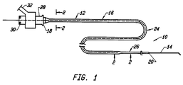
- FIG 1 shows a catheter device 10 constructed according to the present invention.
- the device includes a catheter 12 in the form of an elongated tubular member which will be described below, and a guidewire, here indicated at 14.
- the catheter device is designed for accessing a target site which can be reached only along a small tunnel-like tortuous path within a target tissue, as will be described with reference to Figures 11 and 12 below.
- the catheter 12 includes an elongate outer tubular surface 16 having proximal end 18 connected at a fitting and a distal end.
- the tubular member 12 can be between about 50-300 cm in length, and is typically and more preferably between about 100-200 cm in length.
- the hollow cylindrical area inside the tube 12 or inner lumen 22 ( Figure 2) extending between the two ends has a preferred diameter of less than about 0,1 cm (40 mil), and preferably between about 0,03-0,08 cm (12-30 mil). One mil is one thousandth of an inch, i.e., 0.001 inch.
- the diameter of the inner lumen is between about 0,005-0,02 cm (2-7 mils) greater than that of the diameter of the guidewire 14 carried within the catheter 12.
- the lumen 22 may have a substantially uniform cross-sectional area along its length, or may vary along the catheter length, for example, the distal end may taper toward a small diameter in a direction away from the proximal end.
- the catheter or tubular member 12 includes a relatively stiff proximal segment or segment means 24 (a first section) terminating proximally at end 18, and a relatively more flexible distal segment or segment means 26 (a second section) terminating distally at end 20.
- first segment or proximal segment 24 has greater structural integrity, a greater resistance to bending, and is more stiff than the second or distal segment 26 which has less structural integrity, greater flexibility, and less resistance to bending than the first section.
- either segment can be comprised of a variety of materials it is important that the materials be modified and/or structured so as to obtain the desired differential with respect to the flexibility of the two sections.
- the greater stiffness and less flexibility of the first section 24 relative to the softer or more flexible material of the second segment 26 can be measured quantitatively by the bending forces necessary to bend either segment through an equivalent angle.
- the distal segment is at least about 5 cm long, with the proximal segment providing the remainder of the length of the catheter tubular member. Typically, the proximal segment makes up between about 70%-90% of the total length of the tubular member, and the relatively flexible distal segment makes up the remaining 10%-30% of the length.
- the first or proximal section of the catheter will be referred to as stiffer or less flexible than the second or distal section of the catheter which will be referred to as more flexible and bendable than the first or proximal section.
- the degree of stiffness, flexibility and/or bendability can be measured quantitatively using tests known to those skilled in the art such as the American Society for the Standard of Testing of Materials (hereinafter referred to as ASTM).
- ASTM D747 is generally used in connection with the testing of rectangular pieces of material. Since the present invention is in the form of a tubular catheter, the D747 test was modified for use in connection with the testing of tubular pieces of material.
- ASTM test designated a D747 is incorporated herein by reference for purposes of disclosing methods of testing material with respect to their flexibility.
- the above referred-to ASTM D747 modified test was carried out in connection with sections of tubular material to be used for the first or proximal section of the catheter device.
- the proximal or first section tested under modified D747 testing procedures should give a result of 1050 bar (15,000 psi) or more. Results as high as 4200 bar (60,000 psi) or more are possible. However, it is more likely that the results will yield a reading of about 2800 bar (40,000 psi) or more and are most preferably in the range of about 1750-2450 bar (25- to 35,000 psi) with one particular embodiment providing a result of 2030 bar (29,000 psi).
- Tubular segments of material to be used in connection with the second section or distal section of the catheter were also tested using the ASTM modified D747 testing procedure. These more flexible or bendable segments gave a reading of 700 bar (10,000 psi) or less and are generally in the range of about 490-210 bar (7,000 to 3,000) psi. Although some particularly flexible tubings may have readings below 210 bar (3,000), e.g., about 700 bar (1,000 psi), a particularly preferred material has a reading of about 385 bar (5,500 psi).
- the most flexible D747 reading for the stiffer material 1050 bar (about 15,000 psi) is substantially greater than the least flexible material to be used in connection with the more flexible distal end (about 700 bar (10,000 psi) or less).
- the modified D747 test reading for the stiffer or proximal section is at least 50 percent greater than the reading for the more flexible or distal segment, and is more preferably more than 100 percent greater.
- the stiffer or proximal segment is in the range of 2 to 30 times the D747 reading of the more flexible section and more preferably in the range of about 3 to 8 times greater than the D747 reading of the more flexible section.
- the inner surface wall of the distal segment 26 of the catheter is constructed such that or comprised of a material such as a low-friction coat which allows the guidewire to be moved axially within the catheter through regions of sharp bends or turns.
- a material such as a low-friction coat which allows the guidewire to be moved axially within the catheter through regions of sharp bends or turns.
- the catheter device further includes a proximal end fitting 28 through which the guidewire is received, and through which fluid material can be introduced into the catheter lumen.
- a proximal end fitting 28 through which the guidewire is received, and through which fluid material can be introduced into the catheter lumen.
- One standard fitting which is suitable has a guidewire O-ring seal 30 which can be compressed to provide a suitable seal about the guidewire, while still allowing the wire to be rotated (torqued) and advanced or retracted axially within the catheter, during a catheter placement operation.
- Fluid material can be introduced into the catheter lumen, for example, from a syringe, through port 32.
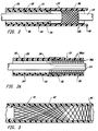
- FIG 2 shows an enlarged cross sectional view of a region of catheter 10 in the region of transition between the two segments, indicated at 2-2 in Figure 1.
- proximal segment 24 is composed of inner 34 and outer 36 coaxial tubes which are tight-fitting and/or essentially integral with respect to each other.
- the stiffness in the proximal segment 24 is provided predominantly by an additional coaxial tube 34.
- the inner, stiffer tube 34 is preferably polypropylene or high-density polyethylene tubing having a wall thickness of between about 0,005-0,01 cm (2-4 mils).
- the outer, more flexible tube is preferably low density polyethylene or silicone tubing, also having a preferred wall thickness of between about 0,005-0,01 cm (2-4 mils).
- high- and low-density polyethylene have the usual trade meaning which is applied to the density grade of polyethylenes which are commonly used in extrusion.
- the materials be low and/or high density polyethylenes or silicon material. Any materials having differing properties of the type described above can be used to make up the two different tubular members. What is important is that the outer tube be comprised of a material of less stiffness and structural integrity and greater flexibility relative to the inner tube which is comprised of a material of greater structural integrity and stiffness and less ability to bend relative to the outer tube.
- the tubes of the different types of materials it is possible to include the first segment which is stiffer and less bendable and the second segment which is flexible and more easily bendable relative to the first segment.
- proximal and distal segments may each be formed as a single layer tube, and joined together at the interface by suitable chemical adhesion and/or by overlapping the two tubes in a short interface region.
- the low-friction surface coat in the catheter is provided by a flexible braided sleeve 38 formed by braid-weaving relatively hard filament material, such as metal, nylon, or filaments of Teflon-like materials.
- the sleeve may be made by conventional braid-weaving methods, such as described in US-A-4,870,887 (disclosing such brands and their method of production), where the density and radial pitch of the braid may be varied according to the weave conditions.
- the filaments used in making the sleeve are very fine platinum filaments, and the sleeve is woven under conditions which produce a loose weave having a radial pitch, defined by the angle of the weave with respect to the radial direction in the sleeve, of between about 20 - 60°.
- the catheter can be constructed, according to one method, by anchoring the proximal end of sleeve 38 between the tubes 34 and 36 forming the proximal segment, as shown in Figure 2.
- the outer tube is preferably a heat-shrink material which is placed over the over the sleeve and inner tube and heat shrunk to form a snug fit over both the inner tube and sleeve 38.
- the sleeve is now anchored at the proximal end and tightly encased along its length by the distal-segment tube.
- the distal segment includes a distal extension 40 which extends beyond the end of sleeve 38. That is, the second or distal segment 26 includes (a) a proximal region having an inner tubular wall surface in which the frictional coefficient between that surface and the guidewire is significantly reduced, and (b) a region where this wall surface provides higher friction, but is an overall lower-mass tip region whose inertial mass is more closely matched with that of the tapered distal region of the guidewire.
- the latter feature reduces the tendency of the catheter to force the guidewire out of a bent or curved condition as the catheter is advanced over the distal end region of the guidewire.
- a relatively low mass at the distal tip region of the catheter may be necessary for tracking the catheter along a tapered region of the guidewire through a sharp bend or turn, even though the reduced catheter mass smaller is gained at the expense of increased friction in this tip region.
- the inertial mass in the distal segment of the catheter can be reduced by decreasing the mass of the sleeve, either by employing a lighter or thinner sleeve filament or by reducing the density of filament(s) in the sleeve.
- a distal segment having combined types of low-friction coat for example, a sleeve coat along a proximal region of the distal segment and one of the lower-mass low-friction coats described in sections B-D along the most distal region of the distal segment.
- Figure 3 shows an alternate embodiment of a sleeve catheter 41, in which the braided sleeve, here indicated at 42, has a continually reduced pitch and weave density in a direction progressing toward the distal tip 44 of the catheter (toward the right in Figure 3).
- the sleeve 42 may be formed by conventional braiding methods, where the angle of filaments taken into the braid weave, and the rate of filament taken into the weave, is varied during weaving to obtain the desired change in braid pitch and density. Moving alone the sleeve 42 to the right it can be understood that the sleeve provides greater flexibility, as well as reduced mass, on progressing distally.
- the internal tubular surface of the distal portion of the catheter is provided with structural features in the form of different types of braided sleeves. These structural features aid in preventing the jamming, sticking or locking of the internal surface of the catheter against an external surface of a guidewire.
- Other structural embodiments are possible. More specifically, the internal surface of the distal portion of the catheter can be constructed to include other structural features different from the braided sleeve which achieves similar results. What is important is that the structural features provide some ability to deflect normal forces which will be applied by the guidewire against the internal tubular surface so as to prevent jamming, sticking or locking of the guidewire against the surface.
- FIG. 2A Another embodiment of the invention in which the braided sleeve described above is replaced with a wound-filament coil.
- the coil 38A is preferably formed of a radio-opaque material, such as platinum, and has a pitch of which is preferably between 1.2-2 times the thickness of the filament.
- the coil 38A may be positioned like the braided sleeve 38 and may be encased in the distal polymer tubing, for example, by heat-shrinking the tube about the coil, as described above.
- the sleeve 38 or 38A may be formed of a radio-opaque filament material, such as platinum, or may be plated or coated with a radio-opaque material, such as gold, for a fluoroscopic viewing.
- Both the above-described braided sleeve 42 and the wound-filament coil 38A described in US-A-4,955,862 provide a structural element which aids in deflecting the distal end or some portion of the distal end of the guidewire from being jammed, stuck or locked against the internal tubular surface.
- Both the coils and the braided sleeves can be constructed in a variety of different manners in order to obtain the desired results of preventing or alleviating the presentation of substantial forces from the distal portion of the guidewire in a direction normal to the surface of the internal tube. Further, both the coils and the braiding can be constructed of a variety of different materials.
- the coils and/or braiding are comprised of materials so as to reduce as much as possible the frictional resistance between the internal surface of the tubing and the external surface of the guidewire. Reduced friction aids in preventing the jamming or locking of the distal end or any part of the second section of the guidewire against the internal surface of the tube, that is, against the outer surface of the braiding or coiling component.
- the low-friction surface coat on the distal segment of the catheter is provided by means of a plurality of low-friction particles embedded in or otherwise attached to the inner wall of the distal segment tube 26.
- the coating includes spherical metal particles embedded in the inner wall of the distal-segment tube has been described in US-A-4 955 862. Briefly, metal spheres having preferred diameters between about 0,003-0,008 cm (1-3 mils) are embedded in the distal segment 26, e.g., as the tube is being extruded.
- the particles are provided in sufficient number such that the surface density of the particles insures substantially uninterrupted contact between the spheres and a guidewire, when the distal segment is advanced over a looped or sharply bent portion of the guidewire.
- the particle density and size is such as to produce sphere-to-sphere contact when the catheter is moved toward a sharply bent configuration.
- the particle density acts to resist catheter bending beyond the point where the particles are brought into contact with one another, thus serving to prevent kinking in the catheter.
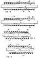
- FIGs 4A and 4B An alternative embodiment of a catheter 46 having a discrete-particle coating is illustrated in Figures 4A and 4B.
- the particles 48 are carbon, preferably graphitic, particles which are deposited on the inner wall of the distal segment in a suitable binder.
- graphite particles 48 such as particles 48 in Figure 4A, in the 0,0013-0,005 cm (1/2 - 2 mil) size range are suspended in a liquid resin mixture 50, such as a mixture of unpolymerized or partially polymerized polyurethane or phenolic resin in the presence of a suitable catalyst, to form a particle slurry 52.
- the slurry is introduced into a distal catheter segment 54 to coat the inner wall 56, as illustrated in Figure 4A.
- the slurry binder is polymerized under solvent-removal conditions, typically by placing the catheter under vacuum and rotating the segment during solvent removal to maintain an even coat during drying. Plasma treatment technologies can be used.
- the final binder coat is indicated at 49 in Figure 4B.
- Methods for preparing and hardening resin mixtures which can be polymerized at relatively low temperatures are known.
- the distal-segment tube may be mechanically or chemically abraded prior to coating, to produce improved bonding of the binder layer to the wall of the tube.
- chemical bonding agents can be incorporated into the binder to bond the polymer in the binder to the segment wall. Such bonding agents are well-known, e.g., as described in US-A-3,698,931 incorporated herein by reference to disclose such bonding agents.
- the carbon particles may be embedded in the inner wall of the distal-segment tube during extrusion, as described above with respect to metal particles.
- low-friction particles such as anti-stick Teflon-like material or nylon beads may be employed in forming the discrete-particles surface coating.
- An advantage of carbon or polymeric beads over metal beads is their lighter weight, which allows better trackability over the tapered region of the guidewire, for the reasons discussed above.
- the carbon or polymer-bead particles may be plated with a radio-opaque material, such as gold, for fluoroscopic viewing.
- Including the particles on the inner surface of the tubular wall provides structural features which aid in deflecting the distal or second section of the guidewire so as to prevent the guidewire from applying substantial forces normal to the surface of the tubular wall and thus prevent sticking, jamming or locking the distal portion of the guidewire against the inner wall surface.
- the particles can be comprised of the above-referred to anti-friction materials which facilitate the movement of the distal end of the guidewire along the inner tubular surface.
- the particle coating embodiment described in this section can include both structural features for deflecting the guidewire and composition (i.e., anti-friction material) features for reducing friction, both of which provide the desired result of the invention which is to avoid to the greatest extent possible the jamming, locking or sticking of the guidewire against the inner tubular surface when the tube and guidewire are bent repeatedly while being moved through a tortuous course.
- composition i.e., anti-friction material
- the low-friction surface coating in the distal segment of the catheter is provided by a relatively hard-surfaced polymer tube.
- a catheter having this general construction is shown at 60 in Figure 5.
- the catheter includes a first or proximal segment 62 formed of a relatively stiff, non-deformable polymer tube 64, such as high-density polyethylene, polyurethane, polypropylene, or Teflon-like material as described above, and a distal segment 66 formed of an outer, relatively flexible, deformable polymer tube 68, and an inner distal extension of tube 64.
- tube 64 is sharply reduced in wall thickness at the transition zone between the two segments, yielding a thin-walled tube section 70 which forms the inner surface 67 of segment 66.
- the wall thickness of the inner tube is between about 0,0013-0,0026 cm (0.5-1 mil), and about 10-20 % of the wall thickness of the outer tube 68.
- the surface 67 can include structural features or be comprised of materials which together or alone prevent jamming of the guidewire 14.
- the catheter can be formed by coextrusion, according to known tube co-extrusion methods, such as detailed in US-A-4,680,156 and 4,499,041, each of which are incorporated herein by reference to disclose such methods.
- the extrusion conditions are adjusted to extrude (a) a single-layer section of relatively rigid polymer tube within a more flexible outer tube, (b) in a transition zone in which the wall-thickness of the inner tube is reduced, and (c) a distal segment in which the inner tube has a fixed, reduced wall thickness.
- the catheter may be constructed by first forming the single proximal tube with the reduced-thickness distal extension, then covering the distal extension with a relatively flexible distal tube.
- the proximal tube and its thin-walled extension can be formed, according to one method, by extrusion processing known to those skilled in the art, or by thinning an end section of the extruded tube by heating and stretching the end portion.
- a constant-thickness proximal tube is machined in its distal region to form the thin-walled portion.
- the outer, more flexible tube in the distal section can be formed over reduced-thickness inner tube section by heat-shrinking the outer tube over the inner one, by binding the two tubes, or by coating the inner tube with a flexible-polymer outer coating, such as by conventional dipping or spraying methods.
- Figure 6 illustrates a catheter 72 in which the proximal tube, indicated at 74, has a gradual taper in a proximal region 76 of a distal segment 78.
- the outer, more flexible tube, shown at 79 has a corresponding taper which preserves the thickness of the wall through the region.
- the catheter may be constructed by coextrusion, or by one of the alternative methods of covering the tapered, reduced-thickness portion of the proximal tube, with a flexible tube, as described above.
- An advantage of this embodiment over the catheter shown in Figure 5 is a reduced tendency of the catheter to kink in the transition region. Also the construction provides greater column strength and torqueability in a region of the distal segment where sharp bends and turns are less likely to be encountered than at the tip region of the catheter.
- the low-friction surface coating in the distal segment of the catheter is produced by chemically hardening the inner wall surface 90 of the distal segment tube 82.
- One catheter embodying this feature is shown at 80 in Figure 7, which shows proximal and distal segments 82, 84, respectively, having the general construction described above.
- the distal segment is formed by a distal extension of an outer tube 86 beyond the end of a stiffer, less deformable inner tube 88.
- the low-friction surface 90 in the catheter is formed by chemically treating the inner surface of the distal-segment tube with a surface hardening agent, such as a polymer cross-linking agent.
- a surface hardening agent such as a polymer cross-linking agent.
- a distal-segment tube formed of a polyurethane/acrylate copolymer may be hardened by treatment with polyisocyanate (see WO-A-86/04591 disclosing such methods of treatment).
- a hydroxylated polymer distal-segment tube such as one made of polyvinyl alcohol, may be cross-linked using ethyl silicate (see EP-A-0 102 315).
- the depth of cross-linking within the distal-segment tube can be controlled by passing a solution of the cross-linking reagent through the tube as it is extruded, or heated.
- the degree of hardness may be controlled by techniques which are well-known in the polymer field.
- the hardened surface coating can also be achieved by coating the wall surface with a hard-surface coating, such as a metal, polymer, or graphitic coating, applied by known sputtering, plating or coating techniques.
- a hard-surface coating such as a metal, polymer, or graphitic coating
- the low-friction surface or coat 90 may be constructed in a variety of different configurations. However, it is most preferable to keep the surface 90 with a highly glossed or smooth configuration in order to take maximum advantage of the anti-friction coating.
- the hardened, highly glossed, smooth surface 90 it is possible to obtain the essential object of the invention which is to reduce any sticking or jamming of the distal end of the guidewire against the surface 90 when the guidewire and tubular catheter must be moved relative to each other and both are in a sharply bent configuration.
- the distal end of the guidewire should be comprised of a material which takes into consideration the composition of the surface 90.
- the two materials that is the material making up the surface 90 and the material making up the surface of the distal end of the guidewire, should be such as to avoid sticking--that is avoid any friction between the two surfaces and thus provide the lowest possible coefficient of friction when these two surfaces are forced against each other and move across each other.
- Figure 8 shows one preferred type of a guidewire 92 which can be used in a catheter device of the present invention.
- Guidewires and their construction have been described in detail in US-A-4,832,047 which is incorporated herein by reference to disclose such.
- the guidewire includes a flexible proximal section 94 having a typical length between about 40-250 cm, an intermediate section 96 having a length between about 0,04-0,15 cm (15-60 mils), and a most flexible (relative to the other sections) distal end section 98 whose length is between about 1-10 cm.
- the core 100 and 102 is tapered from the proximal-section diameter 100 down to a reduced diameter 102 which is preferably about 0,01-0,05 cm (4-20 mils) and between about 10%-50% of the core's proximal segment diameter.
- Two segments 100 and 102 making up the core of the intermediate section of the wire are covered along their length by a flexible polymer covering 104, which functions to provide a smooth outer surface of the intermediate section, and to increase the column strength of the reduced-diameter core in the intermediate section.
- Covering 104 is preferably formed of a polymer, such as Teflon-like material, polyolefin, or polyurethane which can be bonded or otherwise tightly affixed to the core wire.
- the distal section portion of the core is fully or partially encased in a flexible sleeve 106.
- the sleeve shown in Figure 8 is a soft, flexible helical coil which is formed conventionally, e.g., as described above. It is noted that the portion of the guidewire over which the flexible distal segment of the catheter is advanced is predominantly the smooth-walled proximal section, rather than the coil-encased distal wire segment.
- the guidewire may be constructed to include a plurality of different types of coatings on its outer surface.
- the guidewire may be constructed so that the outer surface has structural configurations which aid in preventing the jamming or locking of this outer surface against the inner tubular wall surface of the catheter tube.
- the outer coating of the guidewire may be comprised of materials which aid in reducing the frictional resistance between the outer surface of the guidewire and the inner tubular surface when these two surfaces are moving relative to each other.
- the surfaces of the two components that is the outer surface of the guidewire and the inner tubular wall surface of the catheter, are preferably each constructed with the structural configurations and material compositions of the other in mind so as to obtain the best possible results. More specifically, the structural features and materials used in each component are preferably chosen so as to obtain the least amount of sticking, jamming or locking of the guidewire against the inner tubular surface of the catheter.
- the catheter of the present invention is designed for advancement along a guidewire which has been placed, by movement along a tortuous path, in a highly convoluted bent and/or coiled configuration.
- Figure 9 illustrates a test configuration for measuring the ability of a catheter of the invention to be advanced along a guidewire containing a series of helical windings.
- the guidewire used in this test was a 0,04 cm (14-mil) stainless steel mandrel 108 having a total length of 175 cm.
- the proximal end of the mandrel was clamped to the upper jaw 110 of a conventional tensile test device designed to measure the tensile force applied between two jaws 110 and 112, as the jaws are moved relatively toward or away from one another.
- a distal end portion of the mandrel was formed into a helix 114 having five windings which are numbered 1, 2, 3, 4 and 5 in Figure 9.
- the helix diameter d was about 10 mm, and the helix pitch p, about 5 mm.
- Each catheter (of the type shown in Figure 2A) that was tested was flushed with saline and back loaded over the mandrel until the catheter's distal end was just upstream of the coiled portion of the mandrel.
- the proximal catheter end was locked in jaw 112, as shown, and this jaw was moved downwardly with respect to the stationary jaw 110, to advance the distal segment of the catheter over the coiled portion of the mandrel.
- the tensile force between the two jaws as this movement occurs was measured conventionally, and the force data were recorded on a chart recorder, along with the position of the catheter's tip on the guidewire coil.
- test catheter was one having a 135 cm proximal segment, a 20 cm flexible distal segment, a lumen diameter of 0,06 cm (22 mils), and a 0,06 cm (22 mils) inner diameter closely wound platinum coil sleeve extending along the entire length of the distal segment.
- a control catheter had the same construction, but without the distal segment coil sleeve.
- Figure 10 is a graph which plots the force, in pounds, applied between the jaws in the test device, with respect to the position the distal end of the catheter as advanced along the helix.
- the force curve of the catheter of the present invention is indicated by dash-dot line (the line to the right), and that of the control catheter, by dashed line.
- the data plotted represents the average of three different test runs for each catheter device.
- the catheter of the present invention was able to be advanced over three coil windings with very little force (less than about 0.1 lb), with linearly increasing force being required for advance between the third and fifth coil windings.
- the catheter could be easily advanced over the five-winding helix and only stopped when the proximal segment of the catheter reached the coiled section of the mandrel.
- the force curve of the control catheter indicates the much greater resistance which is encountered in advancing this catheter over a coiled guidewire segment.
- the catheter could be advanced only over one coil winding at low force, with a sharp increase in force required in advancing along the second winding.
- the catheter could not be advanced over two complete guidewire windings.
- FIG. 11 shows a region of soft target tissue 120 such as brain tissue, which includes a portion of a small-vessel, tortuous pathway which must be traversed in reaching a selected target site (not shown).
- the region shown contains vessel 122 which branches into vessel 124, and a vessel 126 which branches from the lower portion of vessel 124.
- the vessels may have diameters typically between about 2-5 mm or less, and the bends at both of the junctions connecting vessel 122 with the lower portion of vessel 124, and vessel 124 with vessel 126 are greater than 90 degrees.
- the guidewire and catheter are first threaded as a unit from an external access site through the vasculature to a region adjacent, but not into the tortuous path region of the target tissue. This is done in the usual case where the catheter must pass through the cardiac aorta by first placing a relatively large-diameter guiding catheter (e.g., about 0,1 cm (40 mils) inner diameter) from the access site through the aorta and toward the target site. The catheter and guidewire are then threaded through the guiding catheter past the aorta, where large-vessel diameters and high blood flow volumes make it difficult or impossible to control the movement and position of the catheter.
- a relatively large-diameter guiding catheter e.g., about 0,1 cm (40 mils) inner diameter
- the catheter and guidewire are controlled to move toward the target site.
- the guidewire is advanced independently along the tortuous path in the target tissue, according to standard wire manipulations, which include rotating or torquing the wire at each bend, to orient the wire toward the next vessel in the pathway.
- the wire when it reaches the junction of vessels 122, 124, is torqued to orient the wire (which has a distal bend) downwardly, and the wire is then advanced with respect to the catheter, into vessel 124.
- the wire is torqued in the opposite direction, and advanced from vessel 124 into 126.
- the catheter is then advanced over the wire, to thread the catheter up to a point near the distal end of the guidewire.
- the bent region of catheter 40 and guidewire 14 in Figure 11 are shown in enlarged sectional view in Figure 12.
- the catheter embodiment shown is that described with respect to Figure 4B; however, the following discussion applies equally to all of the embodiments described herein).
- the spaced particles on the outer sides of each bend are engaged with the guidewire, as the catheter is advanced over the guidewire, to provide a low-friction contact between the wire and catheter lumen.
- the reduced friction due at least in part to the non-deformability of the particles, allows the catheter to be advanced over sharper bends, and with substantially less axial force, than a flexible polymer tube alone.
- the injected material may include: (1) radio-opaque agents for viewing blood vessel anatomy and blood flow characteristics in the target region; (2) vaso-occlusive agents, such as a suspension of collagen fibers which can be used to produce small-artery vaso-occlusion in the tissue region supplied by the target vessel; and (3) pharmacological agents, such as anti-tumor drugs which are effective against identified disease states at the target site.
- novel catheter construction described herein allows for tracking along a tortuous path over a guidewire containing multiple loops or bends whose small radii of curvature, with substantially reduced axial force needed in advancing the wire.
- This feature allows the catheter access to a variety of deep tissue target sites which have been inaccessible heretofore because of inability to advance the catheter along the guidewire and/or locking of catheter with the guidewire in regions of sharp bends.
- the inertial mass contributed by the low-friction surface coating is relatively small, and thus has little effect on the ability of the catheter to track the guidewire over sharp bends or turns in the tapered region of the guidewire.
- the distal segment of the catheter can be readily visualized fluoroscopically, allowing the user to view the extent of catheter advance over a guidewire and thereby better control the catheter placement operation.
- the distal-segment tube can be provided with radio-opaque banding or embedded radio-opaque material to allow fluoroscopic viewing of the distal segment during use.
- the catheter can be easily manufactured using conventional catheter production methods, including coil winding and polymer tube extrusion methods.
Landscapes
- Health & Medical Sciences (AREA)
- Life Sciences & Earth Sciences (AREA)
- Hematology (AREA)
- Animal Behavior & Ethology (AREA)
- Engineering & Computer Science (AREA)
- Anesthesiology (AREA)
- Biomedical Technology (AREA)
- Heart & Thoracic Surgery (AREA)
- Biophysics (AREA)
- Pulmonology (AREA)
- General Health & Medical Sciences (AREA)
- Public Health (AREA)
- Veterinary Medicine (AREA)
- Media Introduction/Drainage Providing Device (AREA)
- Materials For Medical Uses (AREA)
- Ink Jet (AREA)
Priority Applications (1)
| Application Number | Priority Date | Filing Date | Title |
|---|---|---|---|
| DE9007751U DE9007751U1 (de) | 1989-05-22 | 1990-05-22 | Katheter mit einem distalen Segment niedriger Reibung |
Applications Claiming Priority (3)
| Application Number | Priority Date | Filing Date | Title |
|---|---|---|---|
| US355500 | 1982-03-08 | ||
| US07/355,500 US4955862A (en) | 1989-05-22 | 1989-05-22 | Catheter and catheter/guide wire device |
| PCT/US1990/002791 WO1990014123A1 (en) | 1989-05-22 | 1990-05-22 | Catheter with low-friction distal segment |
Publications (3)
| Publication Number | Publication Date |
|---|---|
| EP0473697A1 EP0473697A1 (en) | 1992-03-11 |
| EP0473697A4 EP0473697A4 (en) | 1992-05-13 |
| EP0473697B1 true EP0473697B1 (en) | 1996-08-14 |
Family
ID=23397657
Family Applications (1)
| Application Number | Title | Priority Date | Filing Date |
|---|---|---|---|
| EP90908859A Expired - Lifetime EP0473697B1 (en) | 1989-05-22 | 1990-05-22 | Catheter with low-friction distal segment |
Country Status (9)
| Country | Link |
|---|---|
| US (1) | US4955862A (da) |
| EP (1) | EP0473697B1 (da) |
| JP (1) | JP2825187B2 (da) |
| AT (1) | ATE141173T1 (da) |
| CA (1) | CA2057004C (da) |
| DE (2) | DE9007751U1 (da) |
| DK (1) | DK0473697T3 (da) |
| ES (1) | ES2093028T3 (da) |
| WO (1) | WO1990014123A1 (da) |
Families Citing this family (168)
| Publication number | Priority date | Publication date | Assignee | Title |
|---|---|---|---|---|
| US5312356A (en) * | 1989-05-22 | 1994-05-17 | Target Therapeutics | Catheter with low-friction distal segment |
| US5095915A (en) * | 1990-03-19 | 1992-03-17 | Target Therapeutics | Guidewire with flexible distal tip |
| US5180376A (en) * | 1990-05-01 | 1993-01-19 | Cathco, Inc. | Non-buckling thin-walled sheath for the percutaneous insertion of intraluminal catheters |
| US5484425A (en) * | 1990-05-01 | 1996-01-16 | Cathco, Inc. | Radiopaque non-kinking thin-walled introducer sheath |
| US5242389A (en) * | 1990-07-19 | 1993-09-07 | Sherwood Medical Company | Enteral feeding tube enteral feeding tube with separate stylet lumen |
| US5279596A (en) * | 1990-07-27 | 1994-01-18 | Cordis Corporation | Intravascular catheter with kink resistant tip |
| US5178158A (en) | 1990-10-29 | 1993-01-12 | Boston Scientific Corporation | Convertible guidewire-catheter with soft tip |
| EP0556316B1 (en) * | 1990-11-09 | 1997-01-22 | Boston Scientific Corporation | Guidewire for crossing occlusions in blood vessels |
| US5184627A (en) * | 1991-01-18 | 1993-02-09 | Boston Scientific Corporation | Infusion guidewire including proximal stiffening sheath |
| US5254107A (en) * | 1991-03-06 | 1993-10-19 | Cordis Corporation | Catheter having extended braid reinforced transitional tip |
| CA2062000A1 (en) * | 1991-03-07 | 1992-09-08 | H. Robert Moorehead | Site-selective reinforced catheter and methods of manufacturing and using the reinforced catheter |
| US5244619A (en) * | 1991-05-03 | 1993-09-14 | Burnham Warren R | Method of making catheter with irregular inner and/or outer surfaces to reduce travelling friction |
| US5443907A (en) * | 1991-06-18 | 1995-08-22 | Scimed Life Systems, Inc. | Coating for medical insertion guides |
| CA2068584C (en) * | 1991-06-18 | 1997-04-22 | Paul H. Burmeister | Intravascular guide wire and method for manufacture thereof |
| US5222949A (en) * | 1991-07-23 | 1993-06-29 | Intermed, Inc. | Flexible, noncollapsible catheter tube with hard and soft regions |
| US5308342A (en) * | 1991-08-07 | 1994-05-03 | Target Therapeutics, Inc. | Variable stiffness catheter |
| US5338295A (en) * | 1991-10-15 | 1994-08-16 | Scimed Life Systems, Inc. | Dilatation catheter with polyimide-encased stainless steel braid proximal shaft |
| US6808520B1 (en) * | 1991-12-13 | 2004-10-26 | Endovascular Technologies, Inc. | Dual valve, flexible expandable sheath and method |
| US5146928A (en) * | 1992-01-30 | 1992-09-15 | Theodor Esser | Sampling device for collecting microbiological biopsy specimen |
| US5533987A (en) * | 1992-04-09 | 1996-07-09 | Scimed Lifesystems, Inc. | Dilatation catheter with polymide encased stainless steel braid proximal shaft |
| DK0567285T3 (da) * | 1992-04-21 | 1999-02-15 | Vance Products Inc | Overfladebehandlede medicinske anordninger |
| US5569196A (en) * | 1992-07-21 | 1996-10-29 | Advanced Cardiovascular Systems, Inc. | Trackable intravascular catheter |
| JP3310031B2 (ja) * | 1992-10-23 | 2002-07-29 | テルモ株式会社 | カテーテルチューブ |
| US5358517A (en) * | 1993-01-14 | 1994-10-25 | Medtronic, Inc. | Electrical medical lead with textured stylet guide |
| US5358493A (en) * | 1993-02-18 | 1994-10-25 | Scimed Life Systems, Inc. | Vascular access catheter and methods for manufacture thereof |
| US5335410A (en) * | 1993-03-15 | 1994-08-09 | Burnham Warren R | Method of making ultra small diameter catheters and of reinforced tubular product |
| US5823961A (en) * | 1993-05-12 | 1998-10-20 | Hdc Corporation | Catheter guidewire and flushing apparatus and method of insertion |
| US5606979A (en) * | 1993-05-28 | 1997-03-04 | The Microspring Company Inc. | Guide wire |
| JP3383009B2 (ja) * | 1993-06-29 | 2003-03-04 | テルモ株式会社 | 血管カテーテル |
| US5409455A (en) * | 1993-07-09 | 1995-04-25 | Scimed Life Systems, Inc. | Vascular navigation and visualization assist device |
| US5465733A (en) * | 1993-10-14 | 1995-11-14 | Hinohara; Tomoaki | Guide wire for catheters and method for its use |
| US6673025B1 (en) | 1993-12-01 | 2004-01-06 | Advanced Cardiovascular Systems, Inc. | Polymer coated guidewire |
| US5571073A (en) * | 1994-01-28 | 1996-11-05 | Cordis Corporation | Catheter flexible tip assembly |
| US5562722A (en) * | 1994-03-14 | 1996-10-08 | Medical Evaluation Devices & Instruments Corp. | Multiple electrode catheter |
| US5522819A (en) * | 1994-05-12 | 1996-06-04 | Target Therapeutics, Inc. | Dual coil medical retrieval device |
| US5423774A (en) * | 1994-05-17 | 1995-06-13 | Arrow International Investment Corp. | Introducer sheath with irregular outer surface |
| US5569221A (en) * | 1994-07-07 | 1996-10-29 | Ep Technologies, Inc. | Catheter component bond and method |
| US5497785A (en) * | 1994-07-27 | 1996-03-12 | Cordis Corporation | Catheter advancing guidewire and method for making same |
| US5524337A (en) * | 1994-09-21 | 1996-06-11 | Ep Technologies, Inc. | Method of securing ring electrodes onto catheter |
| US5554114A (en) * | 1994-10-20 | 1996-09-10 | Micro Therapeutics, Inc. | Infusion device with preformed shape |
| US5658264A (en) * | 1994-11-10 | 1997-08-19 | Target Therapeutics, Inc. | High performance spiral-wound catheter |
| WO1996015819A1 (en) * | 1994-11-23 | 1996-05-30 | Navarre Biomedical, Ltd. | Flexible catheter |
| US5722423A (en) * | 1994-12-30 | 1998-03-03 | Annex Medical, Inc. | Tissue removing device |
| US5549580A (en) * | 1995-01-23 | 1996-08-27 | Cordis Corporation | Catheter having a flexible distal tip and method of manufacturing |
| US5593394A (en) * | 1995-01-24 | 1997-01-14 | Kanesaka; Nozomu | Shaft for a catheter system |
| US5662622A (en) * | 1995-04-04 | 1997-09-02 | Cordis Corporation | Intravascular catheter |
| US5713858A (en) * | 1995-04-28 | 1998-02-03 | Medtronic, Inc. | Permanently implantable guiding catheter |
| US5556382A (en) * | 1995-08-29 | 1996-09-17 | Scimed Life Systems, Inc. | Balloon perfusion catheter |
| US5997487A (en) * | 1995-10-11 | 1999-12-07 | Micro Therapeutics, Inc. | Infusion wire having fixed core wire |
| US6027461A (en) * | 1995-10-11 | 2000-02-22 | Micro Therapeutics, Inc. | Infusion guidewire having fixed core wire and flexible radiopaque marker |
| US5843050A (en) * | 1995-11-13 | 1998-12-01 | Micro Therapeutics, Inc. | Microcatheter |
| US5931830A (en) * | 1995-12-07 | 1999-08-03 | Sarcos L.C. | Hollow coil guide wire apparatus for catheters |
| US20030069522A1 (en) | 1995-12-07 | 2003-04-10 | Jacobsen Stephen J. | Slotted medical device |
| US6428489B1 (en) | 1995-12-07 | 2002-08-06 | Precision Vascular Systems, Inc. | Guidewire system |
| US5833632A (en) * | 1995-12-07 | 1998-11-10 | Sarcos, Inc. | Hollow guide wire apparatus catheters |
| US5776115A (en) * | 1996-01-17 | 1998-07-07 | Becton Dickinson And Company | Catheter having a gear-shaped lumen to avert the elimination of fluid flow therein |
| US5836893A (en) * | 1996-03-08 | 1998-11-17 | Scimed Life Systems, Inc. | Intravascular guidewire |
| US6053904A (en) * | 1996-04-05 | 2000-04-25 | Robert M. Scribner | Thin wall catheter introducer system |
| US5690120A (en) * | 1996-05-24 | 1997-11-25 | Sarcos, Inc. | Hybrid catheter guide wire apparatus |
| US6017319A (en) * | 1996-05-24 | 2000-01-25 | Precision Vascular Systems, Inc. | Hybrid tubular guide wire for catheters |
| US5916194A (en) * | 1996-05-24 | 1999-06-29 | Sarcos, Inc. | Catheter/guide wire steering apparatus and method |
| US5899891A (en) * | 1996-09-05 | 1999-05-04 | Epimed International, Inc. | Catheter |
| US6014919A (en) | 1996-09-16 | 2000-01-18 | Precision Vascular Systems, Inc. | Method and apparatus for forming cuts in catheters, guidewires, and the like |
| US6553880B2 (en) | 1996-09-16 | 2003-04-29 | Sarcos, Lc | Micromachining system |
| US6013046A (en) * | 1996-10-16 | 2000-01-11 | Surgin Surgical Instrumentation, Inc. | Sleeve shielded needles for phaco-emulsification devices |
| US6251086B1 (en) | 1999-07-27 | 2001-06-26 | Scimed Life Systems, Inc. | Guide wire with hydrophilically coated tip |
| US5924998A (en) * | 1997-03-06 | 1999-07-20 | Scimed Life System, Inc. | Guide wire with hydrophilically coated tip |
| US7455646B2 (en) | 1997-06-04 | 2008-11-25 | Advanced Cardiovascular Systems, Inc. | Polymer coated guide wire |
| US7494474B2 (en) | 1997-06-04 | 2009-02-24 | Advanced Cardiovascular Systems, Inc. | Polymer coated guidewire |
| US6231565B1 (en) | 1997-06-18 | 2001-05-15 | United States Surgical Corporation | Robotic arm DLUs for performing surgical tasks |
| US5947940A (en) * | 1997-06-23 | 1999-09-07 | Beisel; Robert F. | Catheter reinforced to prevent luminal collapse and tensile failure thereof |
| US6048338A (en) | 1997-10-15 | 2000-04-11 | Scimed Life Systems, Inc. | Catheter with spiral cut transition member |
| US6132388A (en) * | 1997-10-16 | 2000-10-17 | Scimed Life Systems, Inc. | Guide wire tip |
| US6093157A (en) * | 1997-10-22 | 2000-07-25 | Scimed Life Systems, Inc. | Radiopaque guide wire |
| US6273876B1 (en) | 1997-12-05 | 2001-08-14 | Intratherapeutics, Inc. | Catheter segments having circumferential supports with axial projection |
| US6340441B1 (en) | 1998-03-13 | 2002-01-22 | Scimed Life Systems, Inc. | Multi-layer guide wire and method of manufacture therefor |
| US6702972B1 (en) | 1998-06-09 | 2004-03-09 | Diametrics Medical Limited | Method of making a kink-resistant catheter |
| US6171297B1 (en) | 1998-06-30 | 2001-01-09 | Schneider (Usa) Inc | Radiopaque catheter tip |
| US6221066B1 (en) | 1999-03-09 | 2001-04-24 | Micrus Corporation | Shape memory segmented detachable coil |
| US6579246B2 (en) | 1999-12-22 | 2003-06-17 | Sarcos, Lc | Coronary guidewire system |
| BR0110158A (pt) | 2000-04-18 | 2004-12-28 | Mdc Invest Holdings Inc | Dispositivo médico, e, métodos para infundir fluido em um paciente com um dispositivo médico, para fazer transfusão de um dentre sangue e plasma para dentro e para fora de um paciente com um dispositivo médico e para inserir um fio guia em um paciente usando um dispositivo médico portador de agulha |
| US6398743B1 (en) | 2000-07-28 | 2002-06-04 | Mdc Investment Holdings, Inc. | Medical device for inserting a guide wire having a retractable needle |
| EP1582166B1 (en) | 2000-09-07 | 2007-06-27 | Sherwood Services AG | Apparatus for the treatment of the intervertebral disc |
| US6623504B2 (en) | 2000-12-08 | 2003-09-23 | Scimed Life Systems, Inc. | Balloon catheter with radiopaque distal tip |
| WO2003004086A2 (en) | 2001-07-05 | 2003-01-16 | Precision Vascular Systems, Inc. | Troqueable soft tip medical device and method of usage |
| US6607511B2 (en) | 2001-08-09 | 2003-08-19 | Mdc Investment Holdings, Inc. | Medical device with safety flexible needle |
| US6908448B2 (en) * | 2001-08-24 | 2005-06-21 | Dermisonics, Inc. | Substance delivery device |
| DE10147597B4 (de) * | 2001-09-26 | 2004-07-15 | Rehau Ag + Co. | Medizinisches Gerät zum Zu- oder Abführen einer Flüssigkeit oder zum Aufnehmen einer solchen Flüssigkeit, Verwendung eines solchen Geräts, sowie Kunststoff für medizinische Anwendungen |
| US7201763B2 (en) | 2001-10-24 | 2007-04-10 | Boston Scientific Scimed, Inc. | Distal balloon waist material relief and method of manufacture |
| US20040073158A1 (en) * | 2001-12-12 | 2004-04-15 | Medtronic, Inc. | Guide catheter |
| US7065394B2 (en) * | 2001-12-12 | 2006-06-20 | Medtronic, Inc | Guide catheter |
| US20030191451A1 (en) * | 2002-04-05 | 2003-10-09 | Kevin Gilmartin | Reinforced catheter system |
| US20040006354A1 (en) * | 2002-07-02 | 2004-01-08 | Dean Schaefer | Coaxial stretch-resistant vaso-occlusive device |
| US7115134B2 (en) | 2002-07-22 | 2006-10-03 | Chambers Technology, Llc. | Catheter with flexible tip and shape retention |
| US7914467B2 (en) | 2002-07-25 | 2011-03-29 | Boston Scientific Scimed, Inc. | Tubular member having tapered transition for use in a medical device |
| US7878984B2 (en) | 2002-07-25 | 2011-02-01 | Boston Scientific Scimed, Inc. | Medical device for navigation through anatomy and method of making same |
| WO2004038442A2 (en) * | 2002-10-21 | 2004-05-06 | The General Hospital Corporation D/B/A Massachusetts General Hospital | Catheter and radiofrequency coil with annular b1 filed |
| US7547304B2 (en) * | 2002-12-19 | 2009-06-16 | Gore Enterprise Holdings, Inc. | Guidewire-centering catheter tip |
| US8377035B2 (en) | 2003-01-17 | 2013-02-19 | Boston Scientific Scimed, Inc. | Unbalanced reinforcement members for medical device |
| US7169118B2 (en) | 2003-02-26 | 2007-01-30 | Scimed Life Systems, Inc. | Elongate medical device with distal cap |
| US7001369B2 (en) | 2003-03-27 | 2006-02-21 | Scimed Life Systems, Inc. | Medical device |
| US7803395B2 (en) | 2003-05-15 | 2010-09-28 | Biomerix Corporation | Reticulated elastomeric matrices, their manufacture and use in implantable devices |
| US7540845B2 (en) * | 2003-09-05 | 2009-06-02 | Boston Scientific Scimed, Inc | Medical device coil |
| US7833175B2 (en) * | 2003-09-05 | 2010-11-16 | Boston Scientific Scimed, Inc. | Medical device coil |
| US7824345B2 (en) * | 2003-12-22 | 2010-11-02 | Boston Scientific Scimed, Inc. | Medical device with push force limiter |
| US7763077B2 (en) | 2003-12-24 | 2010-07-27 | Biomerix Corporation | Repair of spinal annular defects and annulo-nucleoplasty regeneration |
| US7152837B1 (en) * | 2004-02-24 | 2006-12-26 | James Babjak | Hanger apparatus |
| US20070118165A1 (en) * | 2004-03-08 | 2007-05-24 | Demello Jonathan R | System and method for removal of material from a blood vessel using a small diameter catheter |
| US20080228209A1 (en) * | 2004-03-08 | 2008-09-18 | Demello Richard M | System and method for removal of material from a blood vessel using a small diameter catheter |
| US7632242B2 (en) | 2004-12-09 | 2009-12-15 | Boston Scientific Scimed, Inc. | Catheter including a compliant balloon |
| US7744574B2 (en) | 2004-12-16 | 2010-06-29 | Boston Scientific Scimed, Inc. | Catheter tip to reduce wire lock |
| US8114142B2 (en) * | 2005-03-30 | 2012-02-14 | Boston Scientific Scimed, Inc. | Catheter |
| US20060264904A1 (en) * | 2005-05-09 | 2006-11-23 | Kerby Walter L | Medical device |
| US9445784B2 (en) | 2005-09-22 | 2016-09-20 | Boston Scientific Scimed, Inc | Intravascular ultrasound catheter |
| US7850623B2 (en) | 2005-10-27 | 2010-12-14 | Boston Scientific Scimed, Inc. | Elongate medical device with continuous reinforcement member |
| DE112006003733A5 (de) * | 2005-12-05 | 2008-11-06 | B. Braun Melsungen Ag | Katheterrohr |
| EP1981559B1 (de) | 2006-02-09 | 2016-11-23 | B. Braun Melsungen AG | Faltenballonbeschichtungsverfahren |
| US20070260222A1 (en) * | 2006-05-08 | 2007-11-08 | Kraus Robert G | Catheter having reinforcing rings and method of use |
| US7905877B1 (en) * | 2006-05-12 | 2011-03-15 | Micrus Design Technology, Inc. | Double helix reinforced catheter |
| WO2008014094A2 (en) * | 2006-07-28 | 2008-01-31 | Taylor Medical, Inc. | Catheter components formed of a compound of polymer with particles or fibers |
| US8551020B2 (en) | 2006-09-13 | 2013-10-08 | Boston Scientific Scimed, Inc. | Crossing guidewire |
| US20080108974A1 (en) * | 2006-10-20 | 2008-05-08 | Vital Signs, Inc. | Reinforced catheter with radiopaque distal tip and process of manufacture |
| US8556914B2 (en) | 2006-12-15 | 2013-10-15 | Boston Scientific Scimed, Inc. | Medical device including structure for crossing an occlusion in a vessel |
| US8088097B2 (en) | 2007-11-21 | 2012-01-03 | Glumetrics, Inc. | Use of an equilibrium intravascular sensor to achieve tight glycemic control |
| EP2120680A2 (en) | 2007-02-06 | 2009-11-25 | Glumetrics, Inc. | Optical systems and methods for rationmetric measurement of blood glucose concentration |
| CA2686065A1 (en) | 2007-05-10 | 2008-11-20 | Glumetrics, Inc. | Equilibrium non-consuming fluorescence sensor for real time intravascular glucose measurement |
| US20080312639A1 (en) * | 2007-06-13 | 2008-12-18 | Jan Weber | Hardened polymeric lumen surfaces |
| US8409114B2 (en) | 2007-08-02 | 2013-04-02 | Boston Scientific Scimed, Inc. | Composite elongate medical device including distal tubular member |
| US8105246B2 (en) | 2007-08-03 | 2012-01-31 | Boston Scientific Scimed, Inc. | Elongate medical device having enhanced torque and methods thereof |
| US8821477B2 (en) | 2007-08-06 | 2014-09-02 | Boston Scientific Scimed, Inc. | Alternative micromachined structures |
| US9808595B2 (en) | 2007-08-07 | 2017-11-07 | Boston Scientific Scimed, Inc | Microfabricated catheter with improved bonding structure |
| US7841994B2 (en) | 2007-11-02 | 2010-11-30 | Boston Scientific Scimed, Inc. | Medical device for crossing an occlusion in a vessel |
| US8376961B2 (en) | 2008-04-07 | 2013-02-19 | Boston Scientific Scimed, Inc. | Micromachined composite guidewire structure with anisotropic bending properties |
| WO2009129186A2 (en) | 2008-04-17 | 2009-10-22 | Glumetrics, Inc. | Sensor for percutaneous intravascular deployment without an indwelling cannula |
| US8535243B2 (en) | 2008-09-10 | 2013-09-17 | Boston Scientific Scimed, Inc. | Medical devices and tapered tubular members for use in medical devices |
| US8795254B2 (en) | 2008-12-10 | 2014-08-05 | Boston Scientific Scimed, Inc. | Medical devices with a slotted tubular member having improved stress distribution |
| JP5452026B2 (ja) * | 2009-01-22 | 2014-03-26 | 住友ベークライト株式会社 | カテーテル |
| GB0901945D0 (en) * | 2009-02-09 | 2009-03-11 | Young Peter J | Visualized suction catheter |
| US20110077477A1 (en) | 2009-09-30 | 2011-03-31 | Glumetrics, Inc. | Sensors with thromboresistant coating |
| US8467843B2 (en) | 2009-11-04 | 2013-06-18 | Glumetrics, Inc. | Optical sensor configuration for ratiometric correction of blood glucose measurement |
| US8137293B2 (en) | 2009-11-17 | 2012-03-20 | Boston Scientific Scimed, Inc. | Guidewires including a porous nickel-titanium alloy |
| CA2726418A1 (en) * | 2010-01-12 | 2011-07-12 | Custom Medical Applications, Inc. | Ultrasound guided echogenic catheter and related methods |
| US8551021B2 (en) | 2010-03-31 | 2013-10-08 | Boston Scientific Scimed, Inc. | Guidewire with an improved flexural rigidity profile |
| CN103648574B (zh) | 2010-10-04 | 2016-08-10 | 科维蒂恩有限合伙公司 | 远侧进入抽吸导引导管 |
| WO2012106628A1 (en) | 2011-02-04 | 2012-08-09 | Boston Scientific Scimed, Inc. | Guidewires and methods for making and using the same |
| US9072874B2 (en) | 2011-05-13 | 2015-07-07 | Boston Scientific Scimed, Inc. | Medical devices with a heat transfer region and a heat sink region and methods for manufacturing medical devices |
| US10130789B2 (en) | 2011-06-30 | 2018-11-20 | Covidien Lp | Distal access aspiration guide catheter |
| US9486603B2 (en) | 2013-06-20 | 2016-11-08 | Philip J. Dye | Intermittent urinary catheter |
| US9289575B2 (en) | 2013-06-20 | 2016-03-22 | Philip J. Dye | Catheter |
| US9878125B2 (en) | 2013-06-20 | 2018-01-30 | Zcath Llc | Intermittent urinary catheter |
| JP2014111139A (ja) * | 2013-12-27 | 2014-06-19 | Sumitomo Bakelite Co Ltd | カテーテル |
| US9901706B2 (en) | 2014-04-11 | 2018-02-27 | Boston Scientific Scimed, Inc. | Catheters and catheter shafts |
| US10814120B2 (en) | 2015-07-02 | 2020-10-27 | Covellus Llc | Modular medical device catheter system |
| US11660439B2 (en) | 2015-07-02 | 2023-05-30 | Covellus Llc | Modular medical device system |
| US10328250B2 (en) | 2015-07-02 | 2019-06-25 | Covellus Llc | Medical device adapter |
| US20180303545A1 (en) * | 2015-10-28 | 2018-10-25 | St. Jude Medical, Cardiology Division, Inc. | Ablation Catheter with Ultrasound Transducers for Lesion Assessment and an Ablation Method |
| US11351048B2 (en) | 2015-11-16 | 2022-06-07 | Boston Scientific Scimed, Inc. | Stent delivery systems with a reinforced deployment sheath |
| AU2017212812B2 (en) * | 2016-01-29 | 2021-10-07 | Abiomed, Inc. | Thermoform cannula with variable cannula body stiffness |
| WO2017144128A1 (en) * | 2016-02-26 | 2017-08-31 | Cavis Technologies Ab | Pressure catheter and guide wire assembly |
| JP6993408B2 (ja) * | 2016-09-29 | 2022-01-13 | ラピッド メディカル リミテッド | 作動可能な作業端部を有する回転式の捩り可能な血管内装置 |
| EP4279006A3 (en) * | 2017-06-29 | 2024-02-21 | Asahi Intecc Co., Ltd. | Plasma guide wire |
| WO2019090320A1 (en) * | 2017-11-06 | 2019-05-09 | Covellus Llc | Modular medical device catheter system |
| US11452533B2 (en) | 2019-01-10 | 2022-09-27 | Abbott Cardiovascular Systems Inc. | Guide wire tip having roughened surface |
| WO2020243394A1 (en) * | 2019-05-29 | 2020-12-03 | University Of Pittsburgh - Of The Commonwealth System Of Higher Education | Ventriculoamniotic shunt for fetal aqueductal stenosis |
| EP4041102A4 (en) * | 2019-10-30 | 2024-03-20 | Bard Access Systems, Inc. | CATHETER PERMEABILITY DEVICE |
| US20220134061A1 (en) * | 2020-10-31 | 2022-05-05 | Akshal Patel | Systems for Delivery of Therapies by Trans-maxillary Access |
| WO2024102408A1 (en) | 2022-11-09 | 2024-05-16 | Bard Access Systems, Inc. | Systems for preventing or treating vascular access device-related thrombosis |
| US20240415628A1 (en) * | 2023-06-13 | 2024-12-19 | Mivi Neuroscience, Inc. | Embolic protection device designed in particular for tortuous blood vessels, especially cerebral vessels |
Family Cites Families (13)
| Publication number | Priority date | Publication date | Assignee | Title |
|---|---|---|---|---|
| FR440731A (fr) * | 1912-02-28 | 1912-07-19 | Louis Marie Clement Charnaux | Sonde ou canule armée pour explorations et applications hygiéniques et médicales |
| US3416531A (en) * | 1964-01-02 | 1968-12-17 | Edwards Miles Lowell | Catheter |
| BE788761A (fr) * | 1971-09-14 | 1973-01-02 | Raven Carl B | Ensemble de canule d'infusion |
| US4044765A (en) * | 1975-12-17 | 1977-08-30 | Medical Evaluation Devices And Instruments Corporation | Flexible tube for intra-venous feeding |
| US4368730A (en) * | 1981-02-12 | 1983-01-18 | Nigel Sharrock | Intravenous catheter |
| JPS6021767A (ja) * | 1983-07-18 | 1985-02-04 | テルモ株式会社 | カテ−テルとその製造方法 |
| US4636346A (en) * | 1984-03-08 | 1987-01-13 | Cordis Corporation | Preparing guiding catheter |
| US4705511A (en) * | 1985-05-13 | 1987-11-10 | Bipore, Inc. | Introducer sheath assembly |
| JPH025799Y2 (da) * | 1986-02-07 | 1990-02-13 | ||
| US4676229A (en) * | 1986-04-09 | 1987-06-30 | Welch Allyn, Inc. | Biopsy channel for an endoscope |
| US4739768B2 (en) * | 1986-06-02 | 1995-10-24 | Target Therapeutics Inc | Catheter for guide-wire tracking |
| US4784639A (en) * | 1987-07-06 | 1988-11-15 | Patel Piyush V | Catheter and method of inserting catheter |
| US4863442A (en) * | 1987-08-14 | 1989-09-05 | C. R. Bard, Inc. | Soft tip catheter |
-
1989
- 1989-05-22 US US07/355,500 patent/US4955862A/en not_active Expired - Lifetime
-
1990
- 1990-05-22 CA CA002057004A patent/CA2057004C/en not_active Expired - Lifetime
- 1990-05-22 JP JP2508257A patent/JP2825187B2/ja not_active Expired - Lifetime
- 1990-05-22 WO PCT/US1990/002791 patent/WO1990014123A1/en not_active Ceased
- 1990-05-22 EP EP90908859A patent/EP0473697B1/en not_active Expired - Lifetime
- 1990-05-22 AT AT90908859T patent/ATE141173T1/de active
- 1990-05-22 DE DE9007751U patent/DE9007751U1/de not_active Expired - Lifetime
- 1990-05-22 DE DE69028106T patent/DE69028106T2/de not_active Expired - Fee Related
- 1990-05-22 ES ES90908859T patent/ES2093028T3/es not_active Expired - Lifetime
- 1990-05-22 DK DK90908859.3T patent/DK0473697T3/da active
Also Published As
| Publication number | Publication date |
|---|---|
| CA2057004C (en) | 1995-12-12 |
| JP2825187B2 (ja) | 1998-11-18 |
| EP0473697A4 (en) | 1992-05-13 |
| EP0473697A1 (en) | 1992-03-11 |
| JPH05501506A (ja) | 1993-03-25 |
| US4955862A (en) | 1990-09-11 |
| ATE141173T1 (de) | 1996-08-15 |
| WO1990014123A1 (en) | 1990-11-29 |
| CA2057004A1 (en) | 1990-11-23 |
| DE69028106T2 (de) | 1997-01-16 |
| DK0473697T3 (da) | 1996-09-02 |
| DE9007751U1 (de) | 1995-03-16 |
| ES2093028T3 (es) | 1996-12-16 |
| DE69028106D1 (de) | 1996-09-19 |
Similar Documents
| Publication | Publication Date | Title |
|---|---|---|
| EP0473697B1 (en) | Catheter with low-friction distal segment | |
| US5312356A (en) | Catheter with low-friction distal segment | |
| AU624383B2 (en) | Catheter guide wire | |
| EP0309471B1 (en) | Catheter | |
| US5961511A (en) | Catheter having LCP reinforced distal portion | |
| US5730733A (en) | Flow assisted catheter | |
| US6709429B1 (en) | Intravascular catheter with multiple axial fibers | |
| US6193705B1 (en) | Flow assisted catheter | |
| US6004310A (en) | Multilumen catheter shaft with reinforcement | |
| US6185449B1 (en) | Braidless guide catheter | |
| EP0930910B1 (en) | Guide catheter with enhanced guidewire tracking | |
| US6942654B1 (en) | Intravascular catheter with axial member | |
| WO2000043061A1 (en) | Intravascular catheter with composite reinforcement | |
| US7815975B2 (en) | Catheter having polymer stiffener rings and method of making the same | |
| JP2921895B2 (ja) | カテーテル | |
| AU606829C (en) | Catheter and tissue-accessing method | |
| CA2564294A1 (en) | Intravascular catheter with composite reinforcement |
Legal Events
| Date | Code | Title | Description |
|---|---|---|---|
| PUAI | Public reference made under article 153(3) epc to a published international application that has entered the european phase |
Free format text: ORIGINAL CODE: 0009012 |
|
| 17P | Request for examination filed |
Effective date: 19911121 |
|
| AK | Designated contracting states |
Kind code of ref document: A1 Designated state(s): AT BE CH DE DK ES FR GB IT LI LU NL SE |
|
| A4 | Supplementary search report drawn up and despatched |
Effective date: 19920323 |
|
| AK | Designated contracting states |
Kind code of ref document: A4 Designated state(s): AT BE CH DE DK ES FR GB IT LI LU NL SE |
|
| RAP1 | Party data changed (applicant data changed or rights of an application transferred) |
Owner name: TARGET THERAPEUTICS, INC. |
|
| 17Q | First examination report despatched |
Effective date: 19940720 |
|
| GRAH | Despatch of communication of intention to grant a patent |
Free format text: ORIGINAL CODE: EPIDOS IGRA |
|
| GRAH | Despatch of communication of intention to grant a patent |
Free format text: ORIGINAL CODE: EPIDOS IGRA |
|
| GRAH | Despatch of communication of intention to grant a patent |
Free format text: ORIGINAL CODE: EPIDOS IGRA |
|
| GRAA | (expected) grant |
Free format text: ORIGINAL CODE: 0009210 |
|
| AK | Designated contracting states |
Kind code of ref document: B1 Designated state(s): AT BE CH DE DK ES FR GB IT LI LU NL SE |
|
| REF | Corresponds to: |
Ref document number: 141173 Country of ref document: AT Date of ref document: 19960815 Kind code of ref document: T |
|
| REG | Reference to a national code |
Ref country code: CH Ref legal event code: NV Representative=s name: R. A. EGLI & CO. PATENTANWAELTE |
|
| REG | Reference to a national code |
Ref country code: DK Ref legal event code: T3 |
|
| REF | Corresponds to: |
Ref document number: 69028106 Country of ref document: DE Date of ref document: 19960919 |
|
| ITF | It: translation for a ep patent filed | ||
| REG | Reference to a national code |
Ref country code: ES Ref legal event code: FG2A Ref document number: 2093028 Country of ref document: ES Kind code of ref document: T3 |
|
| ET | Fr: translation filed |
Free format text: CORRECTIONS |
|
| PLBE | No opposition filed within time limit |
Free format text: ORIGINAL CODE: 0009261 |
|
| STAA | Information on the status of an ep patent application or granted ep patent |
Free format text: STATUS: NO OPPOSITION FILED WITHIN TIME LIMIT |
|
| 26N | No opposition filed | ||
| PGFP | Annual fee paid to national office [announced via postgrant information from national office to epo] |
Ref country code: LU Payment date: 19980522 Year of fee payment: 9 |
|
| PGFP | Annual fee paid to national office [announced via postgrant information from national office to epo] |
Ref country code: ES Payment date: 19980526 Year of fee payment: 9 |
|
| PGFP | Annual fee paid to national office [announced via postgrant information from national office to epo] |
Ref country code: BE Payment date: 19980714 Year of fee payment: 9 |
|
| PGFP | Annual fee paid to national office [announced via postgrant information from national office to epo] |
Ref country code: SE Payment date: 19990414 Year of fee payment: 10 |
|
| PGFP | Annual fee paid to national office [announced via postgrant information from national office to epo] |
Ref country code: DK Payment date: 19990512 Year of fee payment: 10 |
|
| PGFP | Annual fee paid to national office [announced via postgrant information from national office to epo] |
Ref country code: GB Payment date: 19990519 Year of fee payment: 10 |
|
| PG25 | Lapsed in a contracting state [announced via postgrant information from national office to epo] |
Ref country code: LU Free format text: LAPSE BECAUSE OF NON-PAYMENT OF DUE FEES Effective date: 19990522 |
|
| PG25 | Lapsed in a contracting state [announced via postgrant information from national office to epo] |
Ref country code: ES Free format text: LAPSE BECAUSE OF NON-PAYMENT OF DUE FEES Effective date: 19990524 |
|
| PGFP | Annual fee paid to national office [announced via postgrant information from national office to epo] |
Ref country code: DE Payment date: 19990525 Year of fee payment: 10 |
|
| PG25 | Lapsed in a contracting state [announced via postgrant information from national office to epo] |
Ref country code: BE Free format text: LAPSE BECAUSE OF NON-PAYMENT OF DUE FEES Effective date: 19990531 |
|
| PGFP | Annual fee paid to national office [announced via postgrant information from national office to epo] |
Ref country code: NL Payment date: 19990531 Year of fee payment: 10 |
|
| BERE | Be: lapsed |
Owner name: TARGET THERAPEUTICS INC. Effective date: 19990531 |
|
| PG25 | Lapsed in a contracting state [announced via postgrant information from national office to epo] |
Ref country code: GB Free format text: LAPSE BECAUSE OF NON-PAYMENT OF DUE FEES Effective date: 20000522 Ref country code: DK Free format text: LAPSE BECAUSE OF NON-PAYMENT OF DUE FEES Effective date: 20000522 |
|
| PG25 | Lapsed in a contracting state [announced via postgrant information from national office to epo] |
Ref country code: SE Free format text: LAPSE BECAUSE OF NON-PAYMENT OF DUE FEES Effective date: 20000523 |
|
| PGFP | Annual fee paid to national office [announced via postgrant information from national office to epo] |
Ref country code: AT Payment date: 20001024 Year of fee payment: 11 |
|
| PGFP | Annual fee paid to national office [announced via postgrant information from national office to epo] |
Ref country code: CH Payment date: 20001031 Year of fee payment: 11 |
|
| PG25 | Lapsed in a contracting state [announced via postgrant information from national office to epo] |
Ref country code: NL Free format text: LAPSE BECAUSE OF NON-PAYMENT OF DUE FEES Effective date: 20001201 |
|
| GBPC | Gb: european patent ceased through non-payment of renewal fee |
Effective date: 20000522 |
|
| EUG | Se: european patent has lapsed |
Ref document number: 90908859.3 |
|
| REG | Reference to a national code |
Ref country code: DK Ref legal event code: EBP |
|
| NLV4 | Nl: lapsed or anulled due to non-payment of the annual fee |
Effective date: 20001201 |
|
| PG25 | Lapsed in a contracting state [announced via postgrant information from national office to epo] |
Ref country code: DE Free format text: LAPSE BECAUSE OF NON-PAYMENT OF DUE FEES Effective date: 20010301 |
|
| PG25 | Lapsed in a contracting state [announced via postgrant information from national office to epo] |
Ref country code: AT Free format text: LAPSE BECAUSE OF NON-PAYMENT OF DUE FEES Effective date: 20010522 |
|
| PG25 | Lapsed in a contracting state [announced via postgrant information from national office to epo] |
Ref country code: LI Free format text: LAPSE BECAUSE OF NON-PAYMENT OF DUE FEES Effective date: 20010621 Ref country code: CH Free format text: LAPSE BECAUSE OF NON-PAYMENT OF DUE FEES Effective date: 20010621 |
|
| REG | Reference to a national code |
Ref country code: ES Ref legal event code: FD2A Effective date: 20010503 |
|
| REG | Reference to a national code |
Ref country code: CH Ref legal event code: PL |
|
| PGFP | Annual fee paid to national office [announced via postgrant information from national office to epo] |
Ref country code: FR Payment date: 20040503 Year of fee payment: 15 |
|
| PG25 | Lapsed in a contracting state [announced via postgrant information from national office to epo] |
Ref country code: IT Free format text: LAPSE BECAUSE OF NON-PAYMENT OF DUE FEES Effective date: 20050522 |
|
| PG25 | Lapsed in a contracting state [announced via postgrant information from national office to epo] |
Ref country code: FR Free format text: LAPSE BECAUSE OF NON-PAYMENT OF DUE FEES Effective date: 20060131 |
|
| REG | Reference to a national code |
Ref country code: FR Ref legal event code: ST Effective date: 20060131 |