EP0472198A2 - Küvettenreinigungsgerät - Google Patents
Küvettenreinigungsgerät Download PDFInfo
- Publication number
- EP0472198A2 EP0472198A2 EP91114091A EP91114091A EP0472198A2 EP 0472198 A2 EP0472198 A2 EP 0472198A2 EP 91114091 A EP91114091 A EP 91114091A EP 91114091 A EP91114091 A EP 91114091A EP 0472198 A2 EP0472198 A2 EP 0472198A2
- Authority
- EP
- European Patent Office
- Prior art keywords
- dilution cup
- cup
- dilution
- cleaning water
- nozzle
- Prior art date
- Legal status (The legal status is an assumption and is not a legal conclusion. Google has not performed a legal analysis and makes no representation as to the accuracy of the status listed.)
- Ceased
Links
Images

Classifications
-
- B—PERFORMING OPERATIONS; TRANSPORTING
- B01—PHYSICAL OR CHEMICAL PROCESSES OR APPARATUS IN GENERAL
- B01L—CHEMICAL OR PHYSICAL LABORATORY APPARATUS FOR GENERAL USE
- B01L13/00—Cleaning or rinsing apparatus
- B01L13/02—Cleaning or rinsing apparatus for receptacle or instruments
-
- B—PERFORMING OPERATIONS; TRANSPORTING
- B01—PHYSICAL OR CHEMICAL PROCESSES OR APPARATUS IN GENERAL
- B01L—CHEMICAL OR PHYSICAL LABORATORY APPARATUS FOR GENERAL USE
- B01L3/00—Containers or dishes for laboratory use, e.g. laboratory glassware; Droppers
- B01L3/50—Containers for the purpose of retaining a material to be analysed, e.g. test tubes
- B01L3/508—Rigid containers without fluid transport within
- B01L3/5082—Test tubes per se
-
- G—PHYSICS
- G01—MEASURING; TESTING
- G01N—INVESTIGATING OR ANALYSING MATERIALS BY DETERMINING THEIR CHEMICAL OR PHYSICAL PROPERTIES
- G01N35/00—Automatic analysis not limited to methods or materials provided for in any single one of groups G01N1/00 - G01N33/00; Handling materials therefor
- G01N35/02—Automatic analysis not limited to methods or materials provided for in any single one of groups G01N1/00 - G01N33/00; Handling materials therefor using a plurality of sample containers moved by a conveyor system past one or more treatment or analysis stations
- G01N35/021—Automatic analysis not limited to methods or materials provided for in any single one of groups G01N1/00 - G01N33/00; Handling materials therefor using a plurality of sample containers moved by a conveyor system past one or more treatment or analysis stations having a flexible chain, e.g. "cartridge belt", conveyor for reaction cells or cuvettes
Definitions
- This invention relates to an apparatus for cleaning a cup used in a body fluid analyzer.
- Dilution cups used in an automatic body fluid analyzer for analyzing a body fluid such as blood or urine are automatically cleaned to prevent carry-over before dilution of samples of the next step.
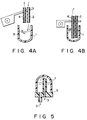
- cleaning water 3 is supplied from a cleaning water supply nozzle 2 into a dilution cup 1, as shown in Fig. 4(A), and the cleaning water is discharged from the cup 1 through a discharging nozzle 4, as shown in Fig. 4(B). These steps are repeated several times.
- cleaning water 3 is continuously supplied to a dilution cup 1 fully sealed by a packing 5 so as to clean the cup 1, as shown in Fig. 5.
- Cleaning water must be increased to reduce carry-over. As a result, the capability of cleaning the cup 1 is adversely lowered. Further, when cleaning water is mixed with a detergent which can easily clean dirt, carry-over can remarkably be reduced. Further, when such a detergent is used, there is such an adverse effect that the detergent may react on a sample to be analyzed.
- the object of this invention is to provide a cup cleaning apparatus which effectively reduces carry-over without using any detergent and without increasing the amount of cleaning water and cleaning time.
- an apparatus for cleaning a dilution cup used in a body fluid analyzer with which is performed an immunological examination for a body fluid such as an examination of infectious disease and determination of blood groups using urine, and blood serum, blood cells and blood plasma, comprising a first inlet for supplying cleaning water into a dilution cup, a second inlet for supplying air into the dilution cup, an outlet for discharging water and air from the dilution cup, and a sealing member for hermetically sealing the dilution cup.
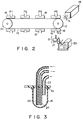
- a dilution cup may be cleaned at a position P4 with its opening directed downward, at a position P5 with the opening directed upward, or at both the positions P4 and P5, as shown in Fig. 2.
- the dilution cup is cleaned as follows: Air bubbles are jetted into water filled in the dilution cup such that innumerable interfaces are formed between the cleaning water and the air bubbles. The interfaces are caused to repeatedly contact the inner wall (particularly, the hemispherical bottom) of he dilution cup innumerable times or air in cleaning water is caused to hit against the inner wall of the dilution cup very strongly.
- the opening of the cup is directed downward, it is preferred that air is supplied from an air supply nozzle to the vicinity of the opening of the dilution cup and the tip of a discharging nozzle is disposed in the vicinity of the bottom of the dilution cup, as shown in Fig. 1.
- the dilution cup, a stem body, and first and second tubes may be made of any material that is not corroded by cleaning water and a sample liquid. More specifically, the cup may be made of vinyl chloride resin. Further, the stem body may be made of stainless steel or the like.
- Fig. 2 shows how to clean dilution cups used in an automatic blood analyzer according to this invention.
- a timing belt 13 is stretched between a pair of pulleys 11 and 12 such that its displacement does not occur when it is driven.
- a first motor 14 is connected to the pulley 12 and rotates the same clockwise (in the direction shown by an arrow A).
- a second motor 15 is provided close to the pulley 12 and vertically is adapted to move a nozzle body 17 made of vinyl chloride for cleaning a dilution cup 16 made of vinyl chloride.
- Each of the dilution cup 16 dispenses a body fluid such as blood plasma, blood cells, blood serum or urine and makes a dilution sample.
- the dilution cups 16 are connected to the timing belt 13 by means of metallic station blocks 18 or the like so as to stop at a position P1 at which samples are dispensed, at a position P2 at which dilution water is dispensed, at a position P3 at which a dilution sample is sucked in and at a position P4 at which the dilution cup is cleaned. More specifically, as shown in Fig. 1, a stepped opening 19 is formed in the station block 18 and a cylindrical holder 20 is fixed to the opening 19 by means of a screw 21.
- a projection 20a extends from the inner wall of the holder 20 inwardly.
- the dilution cup 16 is inserted deepest into the holder 20, the dilution cup 16 is fully fixed into the holder 20 by the elastic force of the projection 20a.
- the cups are positioned at P1, P2, P3 and P4 by the operation of the first motor 14.
- Fig. 1 shows an apparatus for cleaning dilution cups according to this invention.
- the dilution cup 16 is fixed to the holder 20 of a station block 18, with the opening directed downward.
- a cleaning water supply nozzle (first inlet) 22 for supplying cleaning water into the dilution cup 16 and an air supply nozzle (second inlet) 23 for supplying air into the dilution cup 16 are provided on the undersurface of the nozzle body 17.
- a discharging nozzle (outlet) 24 for discharging cleaning water and air from the dilution cup 16 extends from the upper surface of the nozzle body 17 such that its tip is disposed at the vicinity of the hemispherical bottom of the dilution cup 16.
- a pump 25 for supplying cleaning water is connected to a first tube 26 made of vinyl chloride.
- One end of the first tube 26 is connected to the cleaning water supply nozzle 22 and the other end thereof extends in cleaning water 28 in a tank 27 such that the cleaning water 28 is supplied into the dilution cup 16.
- An air supply pump 29 is connected to the air supply nozzle 23 by means of a second tube 30 made of vinyl chloride.
- a ring-shaped rubber packing 31 acting as a seal member for hermetically sealing the dilution cup is attached to the upper surface of the nozzle body 17 by an adhesive so as to be integral with the nozzle body 17 and abut against the edge of the dilution cup 16. However, it is not always necessary that the rubber packing 31 be made integral with the nozzle body.
- the nozzle body 17 is moved up and down by means of a driving mechanism 32 which comprises a third motor 33, a slidable cam 34 driven by means of the rotation of the motor 33, a vertically slidable plate 36 having a bearing 35 in contact with the cam 34, a guide rod 38 connected to the nozzle body 17 by means of a connecting plate 37 for transmitting the driving force of the vertically slidable plate 36 in the vertical directions (in the directions of an arrow B).
- the vertically slidable plate 36 is moved up and down along the upright guide rod 38 in response to the rotational angle of the third motor 33.
- the vertically slidable plate 36 is lifted toward the dilution cup 16 which has been stopped at the position P4 by controlling the rotational angle of the third motor 33 such that the nozzle body 17 is sealingly connected to the dilution cup 16.
- the vertically slidable plate 36 is moved downward by controlling the rotational angle of the third motor 33, whereby the nozzle 17 is separated from the dilution cup 16.
- the cup cleaning apparatus comprises a cleaning water supply nozzle 22 for supplying cleaning water 28 into a dilution cup 16, an air supply nozzle 23 for supplying air into the dilution cup 16, a discharging nozzle 24 for discharging cleaning water and air from the dilution cup 16, and a rubber packing 31 for hermetically sealing the dilution cup 16.
- the effect of cleaning the inner wall of the dilution cup 16 is enhanced without increasing the amount of cleaning water to be used and cleaning time.
- the number of reexamination for checking cup carry-over can be reduced.
- a dilution cup, a cleaning water supply nozzle, an air supply nozzle and a discharging nozzle can be arranged as shown in Fig. 3.
- the dilution cup is set at the position P5 which is disposed at the side opposite to the position P4 in Fig. 2. Since the dilution cup 16 is set such that its opening is directed upward, the tips of the air supply nozzle 23 and the discharging nozzle 24 are disposed at the bottom of the dilution cup 16.
- the cup cleaning device may be set at the position P4 under the timing belt as shown in Fig. 1 and may be set at the position P5 over the timing belt as shown in Fig. 1. Further, the cup cleaning apparatus may be set at both the positions P4 and P5, the effect of cleaning the inner wall of the dilution cups is more increased.
Landscapes
- Health & Medical Sciences (AREA)
- Clinical Laboratory Science (AREA)
- Chemical & Material Sciences (AREA)
- Chemical Kinetics & Catalysis (AREA)
- Automatic Analysis And Handling Materials Therefor (AREA)
Applications Claiming Priority (2)
| Application Number | Priority Date | Filing Date | Title |
|---|---|---|---|
| JP2223615A JP3010057B2 (ja) | 1990-08-24 | 1990-08-24 | カップ洗浄装置 |
| JP223615/90 | 1990-08-24 |
Publications (2)
| Publication Number | Publication Date |
|---|---|
| EP0472198A2 true EP0472198A2 (de) | 1992-02-26 |
| EP0472198A3 EP0472198A3 (en) | 1992-12-02 |
Family
ID=16800979
Family Applications (1)
| Application Number | Title | Priority Date | Filing Date |
|---|---|---|---|
| EP19910114091 Ceased EP0472198A3 (en) | 1990-08-24 | 1991-08-22 | Cup cleaning apparatus |
Country Status (3)
| Country | Link |
|---|---|
| US (1) | US5184634A (de) |
| EP (1) | EP0472198A3 (de) |
| JP (1) | JP3010057B2 (de) |
Cited By (1)
| Publication number | Priority date | Publication date | Assignee | Title |
|---|---|---|---|---|
| US9481852B2 (en) | 2008-01-24 | 2016-11-01 | The Lubrizol Corporation | High viscosity synthetic ester lubricant base stock blends |
Families Citing this family (9)
| Publication number | Priority date | Publication date | Assignee | Title |
|---|---|---|---|---|
| US5419347A (en) * | 1992-11-16 | 1995-05-30 | Ssi Medical Services, Inc. | Automated flushing module |
| US6422249B1 (en) * | 2000-08-10 | 2002-07-23 | Affymetrix Inc. | Cartridge washing system and methods |
| US20040120861A1 (en) * | 2002-10-11 | 2004-06-24 | Affymetrix, Inc. | System and method for high-throughput processing of biological probe arrays |
| US20060246576A1 (en) * | 2005-04-06 | 2006-11-02 | Affymetrix, Inc. | Fluidic system and method for processing biological microarrays in personal instrumentation |
| JP2009080035A (ja) * | 2007-09-26 | 2009-04-16 | Olympus Corp | 分析装置 |
| US8187538B2 (en) | 2008-01-17 | 2012-05-29 | Ortho-Clinical Diagnostics, Inc. | Diluent wells produced in card format for immunodiagnostic testing |
| FR2989602B1 (fr) * | 2012-04-19 | 2014-05-09 | Biomerieux Sa | Procede pour nettoyer des puits a echantillons de test et tete de nettoyage en faisant application |
| CN107167360B (zh) * | 2017-06-16 | 2023-08-15 | 苏州长光华医生物医学工程有限公司 | 一种样本稀释装置 |
| JP7054616B2 (ja) * | 2017-11-13 | 2022-04-14 | 日本電子株式会社 | 自動分析装置 |
Family Cites Families (10)
| Publication number | Priority date | Publication date | Assignee | Title |
|---|---|---|---|---|
| DD109079B (de) * | ||||
| FR644975A (fr) * | 1927-12-01 | 1928-10-17 | Appareil pour effectuer le nettoyage et la stérilisation de bouteilles et récipients analogues | |
| US1854471A (en) * | 1928-05-15 | 1932-04-19 | Owens Illinois Glass Co | Apparatus for producing hollow glassware |
| US2309290A (en) * | 1939-11-25 | 1943-01-26 | Hartford Empire Co | Cooling nozzle for tempering hollow glassware |
| US2811975A (en) * | 1952-09-12 | 1957-11-05 | Tatibana Hideo | Apparatus for complete washing of a container |
| US3120237A (en) * | 1961-03-15 | 1964-02-04 | Pure Oil Co | Crankcase spray device |
| US3849830A (en) * | 1973-09-18 | 1974-11-26 | W Wagner | Test tube washer |
| US3916924A (en) * | 1973-12-28 | 1975-11-04 | Gowan Francis E Mc | Apparatus for emptying and rinsing containers |
| JPS6020701B2 (ja) * | 1976-09-22 | 1985-05-23 | 株式会社日立製作所 | 自動化学分析装置 |
| US4406298A (en) * | 1981-12-14 | 1983-09-27 | Jack Martin | Apparatus for cleaning dye bottles or similar articles |
-
1990
- 1990-08-24 JP JP2223615A patent/JP3010057B2/ja not_active Expired - Fee Related
-
1991
- 1991-08-15 US US07/746,247 patent/US5184634A/en not_active Expired - Lifetime
- 1991-08-22 EP EP19910114091 patent/EP0472198A3/en not_active Ceased
Cited By (1)
| Publication number | Priority date | Publication date | Assignee | Title |
|---|---|---|---|---|
| US9481852B2 (en) | 2008-01-24 | 2016-11-01 | The Lubrizol Corporation | High viscosity synthetic ester lubricant base stock blends |
Also Published As
| Publication number | Publication date |
|---|---|
| JPH04105065A (ja) | 1992-04-07 |
| US5184634A (en) | 1993-02-09 |
| JP3010057B2 (ja) | 2000-02-14 |
| EP0472198A3 (en) | 1992-12-02 |
Similar Documents
| Publication | Publication Date | Title |
|---|---|---|
| US4635665A (en) | Washing apparatus | |
| US5897837A (en) | Dispensing device and Immunoassay apparatus using the same | |
| US4311667A (en) | Delivering apparatus | |
| US5592959A (en) | Pipet washing apparatus | |
| US4456037A (en) | Process of delivering samples and reagents | |
| EP0360487B1 (de) | Verfahren und Vorrichtung zur Bestimmung von in einer Flüssigkeitsprobe enthaltenen Teilchen | |
| EP0503003B1 (de) | Reinigungsverfahren und vorrichtung für reagenzverteilungspipetten | |
| EP0472198A2 (de) | Küvettenreinigungsgerät | |
| US5133373A (en) | Apparatus and method for cleaning reagent delivery probes | |
| EP0527059B1 (de) | Verfahren zum Rühren und zur Probenentnahme einer flüssigen Probe | |
| JPH01141357A (ja) | 自動分析装置のサンプル分注方法 | |
| US5066336A (en) | Method for cleaning reagent delivery probes | |
| JP4443271B2 (ja) | 自動分析装置 | |
| EP0976448A1 (de) | Vorrichtung für automatische synthese | |
| JPH0540123A (ja) | 試料攪拌吸引方法及び装置 | |
| JPH0720602Y2 (ja) | 自動臨床化学アナライザ | |
| JPH0894641A (ja) | 血液等の検査装置における分注ノズルの洗浄装置 | |
| JP3029718B2 (ja) | 自動化学分析装置のサンプリングシステム | |
| JP2003294773A (ja) | 臨床検査自動分析装置、臨床検査自動分析装置の洗浄方法 | |
| JPS58124951A (ja) | 反応管洗浄方法 | |
| JPS6156784B2 (de) | ||
| JPS58189560A (ja) | 分注方法 | |
| JPH02236456A (ja) | サンプリング方法 | |
| JPH0249165A (ja) | 自動分析装置の分注器 | |
| JPH0325369A (ja) | 自動化学分析装置用チェックバルブ |
Legal Events
| Date | Code | Title | Description |
|---|---|---|---|
| PUAI | Public reference made under article 153(3) epc to a published international application that has entered the european phase |
Free format text: ORIGINAL CODE: 0009012 |
|
| 17P | Request for examination filed |
Effective date: 19910918 |
|
| AK | Designated contracting states |
Kind code of ref document: A2 Designated state(s): DE FR GB |
|
| PUAL | Search report despatched |
Free format text: ORIGINAL CODE: 0009013 |
|
| AK | Designated contracting states |
Kind code of ref document: A3 Designated state(s): DE FR GB |
|
| 17Q | First examination report despatched |
Effective date: 19940930 |
|
| GRAG | Despatch of communication of intention to grant |
Free format text: ORIGINAL CODE: EPIDOS AGRA |
|
| STAA | Information on the status of an ep patent application or granted ep patent |
Free format text: STATUS: THE APPLICATION HAS BEEN REFUSED |
|
| 18R | Application refused |
Effective date: 19960929 |