US1854471A - Apparatus for producing hollow glassware - Google Patents
Apparatus for producing hollow glassware Download PDFInfo
- Publication number
- US1854471A US1854471A US277965A US27796528A US1854471A US 1854471 A US1854471 A US 1854471A US 277965 A US277965 A US 277965A US 27796528 A US27796528 A US 27796528A US 1854471 A US1854471 A US 1854471A
- Authority
- US
- United States
- Prior art keywords
- mold
- article
- disk
- tube
- air
- Prior art date
- Legal status (The legal status is an assumption and is not a legal conclusion. Google has not performed a legal analysis and makes no representation as to the accuracy of the status listed.)
- Expired - Lifetime
Links
- 238000001816 cooling Methods 0.000 description 23
- 239000011521 glass Substances 0.000 description 13
- 238000000137 annealing Methods 0.000 description 5
- 230000033001 locomotion Effects 0.000 description 4
- 239000011435 rock Substances 0.000 description 3
- 238000004891 communication Methods 0.000 description 2
- 230000007775 late Effects 0.000 description 2
- 238000000034 method Methods 0.000 description 2
- 102100033740 Tenomodulin Human genes 0.000 description 1
- 101710114852 Tenomodulin Proteins 0.000 description 1
- WYTGDNHDOZPMIW-RCBQFDQVSA-N alstonine Natural products C1=CC2=C3C=CC=CC3=NC2=C2N1C[C@H]1[C@H](C)OC=C(C(=O)OC)[C@H]1C2 WYTGDNHDOZPMIW-RCBQFDQVSA-N 0.000 description 1
- NEHMKBQYUWJMIP-UHFFFAOYSA-N chloromethane Chemical compound ClC NEHMKBQYUWJMIP-UHFFFAOYSA-N 0.000 description 1
- 238000010276 construction Methods 0.000 description 1
- 239000002826 coolant Substances 0.000 description 1
- 239000000284 extract Substances 0.000 description 1
- 238000004519 manufacturing process Methods 0.000 description 1
- 238000012986 modification Methods 0.000 description 1
- 230000004048 modification Effects 0.000 description 1
- 230000000737 periodic effect Effects 0.000 description 1
- 230000001105 regulatory effect Effects 0.000 description 1
- 230000000717 retained effect Effects 0.000 description 1
Images
Classifications
-
- C—CHEMISTRY; METALLURGY
- C03—GLASS; MINERAL OR SLAG WOOL
- C03B—MANUFACTURE, SHAPING, OR SUPPLEMENTARY PROCESSES
- C03B9/00—Blowing glass; Production of hollow glass articles
- C03B9/30—Details of blowing glass; Use of materials for the moulds
- C03B9/38—Means for cooling, heating, or insulating glass-blowing machines or for cooling the glass moulded by the machine
- C03B9/3841—Details thereof relating to direct cooling, heating or insulating of the moulded glass
- C03B9/385—Details thereof relating to direct cooling, heating or insulating of the moulded glass using a tube for cooling or heating the inside, e.g. blowheads
- C03B9/3858—Movable tubes
-
- C—CHEMISTRY; METALLURGY
- C03—GLASS; MINERAL OR SLAG WOOL
- C03B—MANUFACTURE, SHAPING, OR SUPPLEMENTARY PROCESSES
- C03B9/00—Blowing glass; Production of hollow glass articles
- C03B9/30—Details of blowing glass; Use of materials for the moulds
- C03B9/36—Blow heads; Supplying, ejecting or controlling the air
- C03B9/3663—Details thereof relating to internal blowing of the hollow glass
- C03B9/3672—Details thereof relating to internal blowing of the hollow glass using a tube
- C03B9/3681—Movable tubes
Definitions
- the invention re- I- lates to asrnethod and apparatus for causinga rapid and even cooling of the articles in the molds in a manner to prevent excessive stresses and strains beingset up in the glass. For this purpose, provision is made for causing the circulation of cooling air in contact with the interior.
- An object of my invention is to overcome this difiiculty by providing suitable means for n cooling the interior surface of the ware in the -1 mold at approximately the same rate at which the exterior surface is cooled, thereby preventingjeuch severe strains and stresses being set up in the glass during the cooling operasuitable means for -'circulating a cooling medium such ascold air" in contact with the interior surface of the glass in the mold'afte'r thus permitting walls also tends to set up internal strains in tion.
- a cooling medium such ascold air
- a furtherobject of the invention is to in- 60 crease the output of the machines in which the articles are formed.
- the speed at' whiclrf the machines canoperate is often limited by the time required for cooling the articles in the finishing molds.
- the present invention byprovi ingrfor a rapid cooling 0 the article permits the finishing mold to be opened and the article discharged in a com aratively shorttime after being blownto its filiialsha p a much more rapid operation of the machine.
- furtherfeature of the-invention consists in the provision of means by which the cornparativelytthick bottoms of the-bottles orother blown 1 articles can be rapidly cooled.
- the bottoms of the articles are' usually substantially thicker than .the side wallsthereof. Asia result, said bottoms cool comparatively slowly and this unequal rate of cooling of the bottom and side the glass.
- the present invention is designed to overcome t is difficulty by providing means for concentrating-the circulation ofiy' cooling air on the interior bottom surface of walls.
- the invention enables the coolin air to betdirected against any ortions o the f interior surface of the artic' e required and its intensity regulated or varied as may be 0$ necessary to secure the best results, depending on the shape of the article, shape and thickness of the mold, and other variable factors.
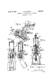
- a .A further object is to provide a device of finishing latter, said fi re being taken along the line II+-II of ig. 1.
- Fig. 3 is a view similar to Fig. 2, showing the injector nozzle retracted to permit e ection of the blown article from the finishing Fig. 4 is a detail sectional view .of another form of the invention.
- the finishing moldcarriage 5 is provided at its lower end with a chamber 6 to contain low pressure cooling air, "said chamber communicating through a port 7 with a passageway .8 leading to. a condu t 9 through ar'ms v10v forming a part of the finishing mold frame '11.
- These pasageways 8 and 9 communicate with each other through annular channels 12 (Fig. 1).
- I finishing mold 13 carried by the frame 11 may be ofconventional or any preferred type and has arms lffulcrumed to a hinge in 15 and slide block 17, the latter mounting a cam roll 18 which is intended to run in a stationary cam (not shown).
- the mold frame 11 carries a roller 19 which runs upon a serpentine 4 track 20 whose shape is such that it swings the finishing moldwertic'ally about the pivot 21 between the horizontal plane and an insection. of the finishing mold during opening the latter'having an enlarged base portion 4 clined position, in *tv hich'latter position ware is ejected from the mold.
- Adevice is provided to engage the upper "ends of articles in the finishing mold to hold them againstlateral movement with either of the latterat the were ejecting position.
- This device includes a disk 22 individual to a finishing mold cavity, said disk fixed to the lower end of a rod 23 movable longitudinally in a guide 24, the latter formed on the outer free end of. an arm 25.
- This arm 25 is carried by a rod 26Iwhose lower end is telescoped within a-sleeve 27,
- a supporting arm 29 (Fig.1), which has a l ongitudinal passageway 30 therethrough communicating elevation of a connected through a series of lin s 16 to a' l g with the conduit 9 through which low pressure cooling air may flow.
- the enlarged base portion 28 is formed with an angular slot' 31 into which .a pin (not shown) carried by the rod 26 projects.
- This rod 26 may be rotatively connected to an extension 32 carrying a cam roll 33 running in a stationary cam-34.
- the cam 34 is shaped to periodically move the extension 32 and rod 26 lengthwise and thereby oscillate the rod 26 and move the disk 22 into and out of operative position relative to the finishing mold.
- the guide 24' (Figs. 2 and 3) for the rod 23 depends from a chambered head 35, the
- the rod 23 (Figs. 2 and 3) carries at its upper end an air motor 40, to the upper end of which air pressure is periodically/supplied through a pipe 41. Constant air'pressure is applied to the lower side of a piston '42 in the air motor cylinder 43 by way of a flexible pipe 44 leading to the cylinder, 43, from the conduit 37 in said arm 25.
- the periodic application of air pressure to the upper side of the differential piston 42 (Fig. 1) is effected by providing a supply pipe 45 connected'to the v flexible pipe section 41, said pipe being supported in g ides 46 (Fig. 1) and leading to a chamber 4
- This chamber 47 communicates through a valved port 48 with the conduit 30, the valve 49 thereforjincluding a stem 50 ex-.
- valve stem 50 is adapted to abut a patch 52 on the cam 34 (Fig. 1) when the mold is first lowered, to thereby unseat'said valve,
- This differential piston carries aninjector tube 55 having an open lower end and projecting downwardly through an axial opening 56 extending through the rod 23 (Fig.2) and the disk 22.
- said tube 55 is formed with a radial port 57 (Fig. 2) intermediate its length, the latter.
- a coil spring 59 encircles the rod 23 and guide 24 between the circular, head an isk 22 to normally yieldingly holdthe dis and rod in a position wherein the annillar' chamber 36- and passageway 58 do not communicate with each other.
- the disk 22 is formed with a series of radial grooves 60 (Figs. 2 and 3) through which cooling air may be exhausted from'the ware in the finishing mold.
- This construction permits the inject on of cooling air and free circulation thereof throu h the article so that the inner andouter. sur aces are substantially uniformly cooled.
- i disk 22 is seated u on the upper end of the article in the finis ing mold. Immediately following this positioning of the disk, the
- valve stem 51 en ages the cam patch'52
- valve 49 is t ereby opened to "admit air pressure to the upper side oi the differential piston 42 in the air motor 40.
- the iston 42 moves downwardly, projecting t e in-' jector tube 55- afionsiderable ggedetermined distance into the article in the ishing mold and simultaneously aligns the port 57 in said tube with the passageway '58 in the rod 23.
- This passageway 58 has previously been- I i brou ht into communication with the annular chamber 36 by movement of-the disk 22 toward the arm 25 as shown in Fig. 2.
- cooling air is inj ected into the article in contact wit all portions of the interior of said article and is exhausted through the radial grooves 60 or ports in the disk 22.
- the cam patch 52 terminates to permit closing of lihp valte 49 and consequent raising of. the differential piston 42 and'injector tube as shown in Fig. 3. This is immediatelg followed :by opening of the finishing'mo'l 13 by any sultable mechanism,
- the disk 22* which seats upon the article in the finishing mold 13, is formed without grooves-or ports, and instead snugly seats upper. end of the article;
- a coil springt is adapt'edto yieldingly hold the disk 22 in its lowermost position as in the" form just described.
- An intermediate portion on the exhaust "tube 67 is formed withscrew threads 68 which engage threads in the differential piston 42.
- the upper end 69 of the tube is shaped for engagement with a suitable .in-' strument by which said .tube may be rotated and thereby change its position in said piston and correspondingly vary its extent of projection into an article in the finishing mold 13.
- V 1 In combination, a mold carriage, a finishing mold frame mounted for vertical swinging movementon the mold carriage, a finishing mold on said frame, a disk, automatic means to seat the disk upon the open upper end of anarticle enclosed in and protruding alcove the finishing mold, the disk when seated loein'g spaced above the mold,
- an injector tube projecting throughsaid disk I into said anticle, means for supplying coola ing air through said tube,means to move the tube inwardly to position its inner end in proximity to .the bottom of the article inthe 'mold, means for withdrawing the tube from said article, means for opening the mold while the disk remains seated on said artiole, and means ⁇ or their withdrawing the disk to releasesaid article.
- a fin shing mold onsaid frame a disk
- injector tube projecting through said disk into said article, means for supplying cool-' ing air through said tube, an air motor operable at regular intervals to project said tube into the article in the finishing mold and to withdraw the tube, means for opening the mold after. the tube is withdrawn and while the disk remains seated on said article, and
- a mold in which hollow articles are given their.final shape, a disk, means forseating the disk uponthe upper end of an article in saidm'old, a pair of telescopicallyarranged tubes extending through the disk and projecting into the article, in themold'. while thefjdisk is seated on said article, said tubes opening into the mold" and providing apathbf-birculation for cooling air within said article, means for injectin cooling air into the article through one tube andcexhaustin it therefrom. to the at mosphere through t eother tribe, means for withdrawing the tubes, means for opening the mold while tlie disk remains seated and supports the article, and means for then withdrawing the disk to release the article. 4.
- a mold in which hol'-.
- a disk means forseatingthe disk upon the upper end of an article in said mold, a air of telescopically grra'nged tubes egtendmg through Y (1 projecting into the article in rovidin 'a-p'ath of circulation [for coolmg air wlthin said article, means .for inject.
- said mold o n at its upper end, a. rock shaft parallel wit the axis of the mold, a rock arm thereom'an injector carried by said arm rawing the disk to release the article,- and means toaxially adjust the tubes relative to .each other'to therebyivary the path of'move ment of the air in the articleandthus regu-' 7 late the intensity ofcooling air applied tothe lower portions of the article.
Landscapes
- Engineering & Computer Science (AREA)
- Chemical & Material Sciences (AREA)
- Manufacturing & Machinery (AREA)
- Materials Engineering (AREA)
- Organic Chemistry (AREA)
- Moulds For Moulding Plastics Or The Like (AREA)
Description
April 19, 1932. v. E. HOFMANN APPARATUS FOR PRODUCING HOLLOW GLASSWARE Filed May 15,
I NITFZD STATES PATENT orluclz VICTOR E. HO FMANN, OF TOLEDO, OHIO, ASSIGINOR 'IO OWENS-ILLINOIS GLASS COM- PANY, OF TOLEDO, OHIO, A CORPORATION OF OHIO arrmrus For. raonocme HoLLow GLAssWARE' application fllanay 15, 1928. Serial 110. 277,965.
5 theshape of the finished articles, the blown iji'ifticles being then retained in the molds until they have cooled and hardened sufliciently to retain their shape after themolds are opened. More specifically, the invention re- I- lates to asrnethod and apparatus for causinga rapid and even cooling of the articles in the molds in a manner to prevent excessive stresses and strains beingset up in the glass. For this purpose, provision is made for causing the circulation of cooling air in contact with the interior. surface of the-glass in the mold after the article has been blown to its to its' 'discharge from the mold V ln accordance with; the usua l practice in the manufacture of such articles," the "cooling of the glass after it is blown to itsfinal form is caused mainly by its contact with the come paratively coldi mold which rapidly extracts f the heat from the glass. As the mold is in contact with only the exterior surface of the glass, such s'urfaceis cooled and hardens'much more rapidly than'the interior surface, with the result that severe stresses and strains are set" up in the glass. It is olificult, if not impossi ble, to entirely remove these strains during "the annealing of the ware, and theprocss of annealing is rendered much more dificult and requires considerably longer time than would be required with ware in which the introduction'of such strains has been'avoided.
- An object of my invention is to overcome this difiiculty by providing suitable means for n cooling the interior surface of the ware in the -1 mold at approximately the same rate at which the exterior surface is cooled, thereby preventingjeuch severe strains and stresses being set up in the glass during the cooling operasuitable means for -'circulating a cooling medium such ascold air" in contact with the interior surface of the glass in the mold'afte'r thus permitting walls also tends to set up internal strains in tion. For-"this purpose, there is provided:
- the article to any extent necessary to cause it to be cooled at the same rate as the side extent of the surface to which it is applied. In this manner, the heatflna be extracted from the glass through both t e interior and exterior surfaces at approximately the same rate, thereby reducing the strains set up andconsequently facilitating the annealing op;
GI'fllJlOII, and moreover .result1ng.1n ware which is entirely or comparatively free from internal strains.
A furtherobject of the invention is to in- 60 crease the output of the machines in which the articles are formed. The speed at' whiclrf the machines canoperate is often limited by the time required for cooling the articles in the finishing molds. By the provision of means for circulating cooling air within the articles in the molds, in the manner above filial shapeand while it is coolingfprelimi ;'indicated, said articles are cooled sufliciently to retain their shape, in much less time than is required by .the'us'ual operation in which the air in the article is quiescent during the coolin process. The present invention, byprovi ingrfor a rapid cooling 0 the article permits the finishing mold to be opened and the article discharged in a com aratively shorttime after being blownto its filiialsha p a much more rapid operation of the machine. g furtherfeature of the-invention consists in the provision of means by which the cornparativelytthick bottoms of the-bottles orother blown 1 articles can be rapidly cooled. In the present day methods of making such articles, there is not an entirely even distribution of the glass, butthe' bottoms of the articles are' usually substantially thicker than .the side wallsthereof. Asia result, said bottoms cool comparatively slowly and this unequal rate of cooling of the bottom and side the glass. The present invention is designed to overcome t is difficulty by providing means for concentrating-the circulation ofiy' cooling air on the interior bottom surface of walls. The invention enables the coolin air to betdirected against any ortions o the f interior surface of the artic' e required and its intensity regulated or varied as may be 0$ necessary to secure the best results, depending on the shape of the article, shape and thickness of the mold, and other variable factors. a e
a .A further object is to provide a device of finishing latter, said fi re being taken along the line II+-II of ig. 1.
Fig. 3 is a view similar to Fig. 2, showing the injector nozzle retracted to permit e ection of the blown article from the finishing Fig. 4 is a detail sectional view .of another form of the invention. a
In the drawings, the finishing moldcarriage 5 is provided at its lower end with a chamber 6 to contain low pressure cooling air, "said chamber communicating through a port 7 with a passageway .8 leading to. a condu t 9 through ar'ms v10v forming a part of the finishing mold frame '11. These pasageways 8 and 9 communicate with each other through annular channels 12 (Fig. 1). The
I finishing mold 13 carried by the frame 11 may be ofconventional or any preferred type and has arms lffulcrumed to a hinge in 15 and slide block 17, the latter mounting a cam roll 18 which is intended to run in a stationary cam (not shown). The mold frame 11 carries a roller 19 which runs upon a serpentine 4 track 20 whose shape is such that it swings the finishing moldwertic'ally about the pivot 21 between the horizontal plane and an insection. of the finishing mold during opening the latter'having an enlarged base portion 4 clined position, in *tv hich'latter position ware is ejected from the mold. l
Adevice is provided to engage the upper "ends of articles in the finishing mold to hold them againstlateral movement with either of the latterat the were ejecting position.
f This device includes a disk 22 individual to a finishing mold cavity, said disk fixed to the lower end of a rod 23 movable longitudinally in a guide 24, the latter formed on the outer free end of. an arm 25.
This arm 25 is carried by a rod 26Iwhose lower end is telescoped within a-sleeve 27,
28 formed at the outer end of a supporting arm 29 (Fig.1), which has a l ongitudinal passageway 30 therethrough communicating elevation of a connected through a series of lin s 16 to a' l g with the conduit 9 through which low pressure cooling air may flow. The enlarged base portion 28 is formed with an angular slot' 31 into which .a pin (not shown) carried by the rod 26 projects. This rod 26 may be rotatively connected to an extension 32 carrying a cam roll 33 running in a stationary cam-34. The cam 34 is shaped to periodically move the extension 32 and rod 26 lengthwise and thereby oscillate the rod 26 and move the disk 22 into and out of operative position relative to the finishing mold.
The guide 24' (Figs. 2 and 3) for the rod 23 depends from a chambered head 35, the
l The conduit 37 through the arm 25 isat all times in communication with an axial passagieway 38 (Fig. 1) through the rod-26..- A ra ial port 39 at one end of said passageway 38 communicates with the conduit 30 in the supportin arm 29.
The rod 23 (Figs. 2 and 3) carries at its upper end an air motor 40, to the upper end of which air pressure is periodically/supplied through a pipe 41. Constant air'pressure is applied to the lower side of a piston '42 in the air motor cylinder 43 by way of a flexible pipe 44 leading to the cylinder, 43, from the conduit 37 in said arm 25 The periodic application of air pressure to the upper side of the differential piston 42 (Fig. 1) is effected by providing a supply pipe 45 connected'to the v flexible pipe section 41, said pipe being supported in g ides 46 (Fig. 1) and leading to a chamber 4 This chamber 47 communicates through a valved port 48 with the conduit 30, the valve 49 thereforjincluding a stem 50 ex-.
.tendin across said conduit and through one wall 0 p the latter. I
The outwardly projecting end 51 of valve stem 50 is adapted to abut a patch 52 on the cam 34 (Fig. 1) when the mold is first lowered, to thereby unseat'said valve,
49 and apply air pressure to the upper side of the differential piston 42 to move the lat ter to the position shown in Fig. 2. This differential piston carries aninjector tube 55 having an open lower end and projecting downwardly through an axial opening 56 extending through the rod 23 (Fig.2) and the disk 22. When the finishing mold first assumesthg position shown in Fig. 1, the cam patch 52 unseatsthe valve 49 to thereby the p admit air pressure into the motor cylinder above the difierential piston 42 causing the.
latter to move downwardly and project the injector tube 55 downwardly a-considerable distance into the blown article in the mold.
In order that cooling air or airpressure may be circulated througn the blown article, said tube 55 is formed with a radial port 57 (Fig. 2) intermediate its length, the latter.
I adapted to register with a passageway 58 which communicates at times with the chamber 36 extending about the rod 23.
A coil spring 59 encircles the rod 23 and guide 24 between the circular, head an isk 22 to normally yieldingly holdthe dis and rod in a position wherein the annillar' chamber 36- and passageway 58 do not communicate with each other.
The disk 22 is formed with a series of radial grooves 60 (Figs. 2 and 3) through which cooling air may be exhausted from'the ware in the finishing mold. This construction permits the inject on of cooling air and free circulation thereof throu h the article so that the inner andouter. sur aces are substantially uniformly cooled. After a parison has been placed in the-fin- 1 ishing mold'13 and blown to its final form,'the 2o finishlng mold 'frame is lowered to the posi-- ction shown in Fig. 1. At 'a predetermined station, the cam 34 operates toswing the disk carrying arm 25 to a position in which the.
i disk 22 is seated u on the upper end of the article in the finis ing mold. Immediately following this positioning of the disk, the
valve stem 51 en ages the cam patch'52, and
, the valve 49 is t ereby opened to "admit air pressure to the upper side oi the differential piston 42 in the air motor 40. The iston =42 moves downwardly, projecting t e in-' jector tube 55- afionsiderable ggedetermined distance into the article in the ishing mold and simultaneously aligns the port 57 in said tube with the passageway '58 in the rod 23.
This passageway 58 has previously been- I i brou ht into communication with the annular chamber 36 by movement of-the disk 22 toward the arm 25 as shown in Fig. 2.
During maintenance-of such relative posi-' tioning of the elements, cooling air is inj ected into the article in contact wit all portions of the interior of said article and is exhausted through the radial grooves 60 or ports in the disk 22. At a predetermined vpoint in'advance of arrival at the vvafre eject- 1 ing station, the cam patch 52 terminates to permit closing of lihp valte 49 and consequent raising of. the differential piston 42 and'injector tube as shown in Fig. 3. This is immediatelg followed :by opening of the finishing'mo'l 13 by any sultable mechanism,
after which the coil spring 61 encircling the rod 26 expands to move the'arm 2a laterally upoh and closes the and upwardly away from the article so that the-latter? may be discharged from the mold In another form of the lnvention (Fig. 4), the disk 22* which seats upon the article in the finishing mold 13, is formed without grooves-or ports, and instead snugly seats upper. end of the article;
A coil springt!) is adapt'edto yieldingly hold the disk 22 in its lowermost position as in the" form just described. I
.An injector tube 65 is threaded to an ex-.
"tension. on the lower side of l the piston 42, and extends downwardly through an axial opening in the rod 23, said tube having its lower end closed, and a series of downwardly' inclined exhaust ports 66 inits side walls. These ports are preferably arranged at anangle to insure application of {cooling air to the lower portions of the articles, as well as the upper portions. An exhaust tube or pipe 67 extends through the injector tube 65 and projects upwardly through the air motor cylof said cylinder. v
An intermediate portion on the exhaust "tube 67 is formed withscrew threads 68 which engage threads in the differential piston 42., The upper end 69 of the tube is shaped for engagement with a suitable .in-' strument by which said .tube may be rotated and thereby change its position in said piston and correspondingly vary its extent of projection into an article in the finishing mold 13., By this arrangement,'the spacing between the lowenend of theexhaust tube 67 and the bottom of theearticle being cooled may be varied to thereby assist in the con inder 43 and outwardly above the upper end ment by cooling air as above described is in better condition for annealing than ware 'produced according to' common practice. A more unltorm temperature condition throughout the glassware is present when the were is discharged from the mold "and consequently better annealing in the ordinary leer is obtainable. p 4 Modifications ma be resorted to within the spirit and scope o the appended claims.
What ll. claim is: V 1. In combination, a mold carriage, a finishing mold frame mounted for vertical swinging movementon the mold carriage, a finishing mold on said frame, a disk, automatic means to seat the disk upon the open upper end of anarticle enclosed in and protruding alcove the finishing mold, the disk when seated loein'g spaced above the mold,
an injector tube projecting throughsaid disk I into said anticle, means for supplying coola ing air through said tube,means to move the tube inwardly to position its inner end in proximity to .the bottom of the article inthe 'mold, means for withdrawing the tube from said article, means for opening the mold while the disk remains seated on said artiole, and means {or their withdrawing the disk to releasesaid article. k
2. In'combination, a mold carriage, a finishing mold frame mounted for' vertical swinging movement on the mold carriage,
a fin shing mold onsaid frame, a disk, automatic means to seat the disk upon the open upper end of an article enclosed 'in and 1'0- i the disk a the mold while the disk is-seated on said ar 'ticle, said tubes .opening into the moldhindtruding' above the finishing mold, the when seated being spaced above the mold, an
injector tube projecting through said disk into said article, means for supplying cool-' ing air through said tube, an air motor operable at regular intervals to project said tube into the article in the finishing mold and to withdraw the tube, means for opening the mold after. the tube is withdrawn and while the disk remains seated on said article, and
means forithen withdrawing. the disk to release said article. I
.3. In combination, a mold in which hollow articles are given their.final shape, a disk, means forseating the disk uponthe upper end of an article in saidm'old, a pair of telescopicallyarranged tubes extending through the disk and projecting into the article, in themold'. while thefjdisk is seated on said article, said tubes opening into the mold" and providing apathbf-birculation for cooling air within said article, means for injectin cooling air into the article through one tube andcexhaustin it therefrom. to the at mosphere through t eother tribe, means for withdrawing the tubes, means for opening the mold while tlie disk remains seated and supports the article, and means for then withdrawing the disk to release the article. 4. In combination, a mold in which hol'-.
lowarticlesare given their final shape, a disk, means forseatingthe disk upon the upper end of an article in said mold, a air of telescopically grra'nged tubes egtendmg through Y (1 projecting into the article in rovidin 'a-p'ath of circulation [for coolmg air wlthin said article, means .for inject.
oolingair into-the article through one and, exhaustin it therefrom to the at; mosphere through t e other tube, meansfor withdrawing the tubes, means for o ening the omprisin'g inner and outer tubes, means for projecting the tubes downvfiird into the interior of the article in the mold and for withdrawing the tubes,means for causing circu- 'arm thereon, an injector carried by said arm comprising inner and outer tubes, means for projecting the tubes downward into the interipr of tlfe article-in the mold and for with:- drawing the tubesgneans for causing circulatlon of' cooling air downward through one tube into said article and exhausting it upward through the other tube, said means for projecting and withdrawing the tubes comprising a piston motor, va valve automatically open bythe projection of the injector tubes into said article for establishing said circulation of the cooling air, means for with-. drawing the mold from said article after said circulation of cooling air therein, and means learned by said rock arm 'fortemporarily supporting the article drawn.- v i Signed at Toledo, in the county of Lucas and Stateof Ohio, this 14th day of-May,
. VICTQR E. HOFMANN.
after the'mold is witha mold while the disk remains seate and suports the: article,"and means for then 'with- .5, In a machine for forming hollow glass articles; the combination of afinishing mold in which'an article is blown to finished form,
said mold o n at its upper end, a. rock shaft parallel wit the axis of the mold, a rock arm thereom'an injector carried by said arm rawing the disk to release the article,- and means toaxially adjust the tubes relative to .each other'to therebyivary the path of'move ment of the air in the articleandthus regu-' 7 late the intensity ofcooling air applied tothe lower portions of the article.
Priority Applications (1)
| Application Number | Priority Date | Filing Date | Title |
|---|---|---|---|
| US277965A US1854471A (en) | 1928-05-15 | 1928-05-15 | Apparatus for producing hollow glassware |
Applications Claiming Priority (1)
| Application Number | Priority Date | Filing Date | Title |
|---|---|---|---|
| US277965A US1854471A (en) | 1928-05-15 | 1928-05-15 | Apparatus for producing hollow glassware |
Publications (1)
| Publication Number | Publication Date |
|---|---|
| US1854471A true US1854471A (en) | 1932-04-19 |
Family
ID=23063117
Family Applications (1)
| Application Number | Title | Priority Date | Filing Date |
|---|---|---|---|
| US277965A Expired - Lifetime US1854471A (en) | 1928-05-15 | 1928-05-15 | Apparatus for producing hollow glassware |
Country Status (1)
| Country | Link |
|---|---|
| US (1) | US1854471A (en) |
Cited By (35)
| Publication number | Priority date | Publication date | Assignee | Title |
|---|---|---|---|---|
| US2495253A (en) * | 1945-03-14 | 1950-01-24 | Armstrong Cork Co | Method and apparatus for forming articles of hollow glassware |
| US2628382A (en) * | 1946-03-06 | 1953-02-17 | Karl Kiefer Machine Company | Spout for air-cleaning containers and means for operating it |
| US2640298A (en) * | 1950-08-02 | 1953-06-02 | Henry C Daubenspeck | Glassware blowhead arrangement |
| US2645059A (en) * | 1951-03-05 | 1953-07-14 | Emhart Mfg Co | Apparatus for and method of forming paste mold glassware |
| US2833088A (en) * | 1954-08-31 | 1958-05-06 | Owens Illinois Glass Co | Glassware cooling and transferring apparatus |
| US2837871A (en) * | 1954-11-01 | 1958-06-10 | Owens Illinois Glass Co | Glass blowing device |
| DE1032484B (en) * | 1953-10-22 | 1958-06-19 | Berliner Maschb Actien Ges Vor | Cooling device for glass bodies in bottle blowing machines |
| DE1054670B (en) * | 1956-01-18 | 1959-04-09 | Owens Illinois Glass Co | Kuelbelblasvorrichtung |
| US2935825A (en) * | 1956-02-28 | 1960-05-10 | Gen Electric Co Ltd | Manufacture of electric incandescent lamps and similar devices |
| US3125429A (en) * | 1964-03-17 | Xf nexk finish | ||
| US3186822A (en) * | 1961-07-07 | 1965-06-01 | Owens Illinois Glass Co | Glassware cooling and transfer apparatus |
| US3236620A (en) * | 1962-03-14 | 1966-02-22 | Corning Glass Works | Glass blowing machine blowhead and article cooling tube combination |
| US3328148A (en) * | 1963-06-19 | 1967-06-27 | Corning Glass Works | Glass-forming method |
| US3654662A (en) * | 1970-06-15 | 1972-04-11 | Cardic Machine Products Inc | Rug cleaning machine |
| US3775945A (en) * | 1970-12-16 | 1973-12-04 | Hesser Ag Maschf | Apparatus for inflating bags |
| US3849830A (en) * | 1973-09-18 | 1974-11-26 | W Wagner | Test tube washer |
| US4377880A (en) * | 1981-02-27 | 1983-03-29 | The United States Of America As Represented By The United States Department Of Energy | Cleaning method and apparatus |
| EP0117630A1 (en) * | 1983-01-29 | 1984-09-05 | Emhart Industries, Inc. | Manufacturing containers out of glass |
| US4553999A (en) * | 1984-04-16 | 1985-11-19 | Aga, A.B. | Methods and apparatus for blow molding glass articles |
| US4652292A (en) * | 1984-04-16 | 1987-03-24 | Aga Ab | Methods for forming glass articles |
| US4708730A (en) * | 1984-04-16 | 1987-11-24 | Aga Ab | Apparatus for blow molding glass articles |
| US5010908A (en) * | 1990-01-29 | 1991-04-30 | Eastman Kodak Company | Apparatus for cleaning the interior of elongated tubular objects |
| US5184634A (en) * | 1990-08-24 | 1993-02-09 | Olympus Optical Co., Ltd. | Cup cleaning apparatus |
| US5428861A (en) * | 1993-08-02 | 1995-07-04 | Motorola | Method and apparatus for cleaning a processing tube |
| US5616184A (en) * | 1993-03-29 | 1997-04-01 | Johnson & Johnson Vision Products, Inc. | Solution removal nozzle |
| WO1997034842A1 (en) * | 1996-03-20 | 1997-09-25 | Oberland Glas Ag | Gripper arrangement for transferring glass articles from finishing moulds in a glass-making machine to a cooling device |
| US20020116953A1 (en) * | 2001-02-28 | 2002-08-29 | Erkki Yli-Vakkuri | Apparatus for bending glass panels |
| US20030101761A1 (en) * | 2001-12-05 | 2003-06-05 | Fenton F. Alan | Glass container forming machine |
| US20030101754A1 (en) * | 2001-12-05 | 2003-06-05 | Hyre Matthew R. | Glass container forming machine |
| US20030101768A1 (en) * | 2001-12-05 | 2003-06-05 | Hyre Matthew R. | Glass container forming machine |
| US20030101764A1 (en) * | 2001-12-05 | 2003-06-05 | Hyre Matthew R. | Glass container forming machine |
| US20030101762A1 (en) * | 2001-12-05 | 2003-06-05 | Hyre Matthew R. | Glass container forming machine |
| US20030101757A1 (en) * | 2001-12-05 | 2003-06-05 | Hyre Matthew R. | Glass container forming machine |
| US20030101767A1 (en) * | 2001-12-05 | 2003-06-05 | Hyre Matthew R. | Glass container forming machine |
| US6705121B2 (en) | 2001-12-05 | 2004-03-16 | Emhart Glass S.A. | Glass container forming machine |
-
1928
- 1928-05-15 US US277965A patent/US1854471A/en not_active Expired - Lifetime
Cited By (43)
| Publication number | Priority date | Publication date | Assignee | Title |
|---|---|---|---|---|
| US3125429A (en) * | 1964-03-17 | Xf nexk finish | ||
| US2495253A (en) * | 1945-03-14 | 1950-01-24 | Armstrong Cork Co | Method and apparatus for forming articles of hollow glassware |
| US2628382A (en) * | 1946-03-06 | 1953-02-17 | Karl Kiefer Machine Company | Spout for air-cleaning containers and means for operating it |
| US2640298A (en) * | 1950-08-02 | 1953-06-02 | Henry C Daubenspeck | Glassware blowhead arrangement |
| US2645059A (en) * | 1951-03-05 | 1953-07-14 | Emhart Mfg Co | Apparatus for and method of forming paste mold glassware |
| DE1032484B (en) * | 1953-10-22 | 1958-06-19 | Berliner Maschb Actien Ges Vor | Cooling device for glass bodies in bottle blowing machines |
| US2833088A (en) * | 1954-08-31 | 1958-05-06 | Owens Illinois Glass Co | Glassware cooling and transferring apparatus |
| US2837871A (en) * | 1954-11-01 | 1958-06-10 | Owens Illinois Glass Co | Glass blowing device |
| DE1054670B (en) * | 1956-01-18 | 1959-04-09 | Owens Illinois Glass Co | Kuelbelblasvorrichtung |
| US2935825A (en) * | 1956-02-28 | 1960-05-10 | Gen Electric Co Ltd | Manufacture of electric incandescent lamps and similar devices |
| US3186822A (en) * | 1961-07-07 | 1965-06-01 | Owens Illinois Glass Co | Glassware cooling and transfer apparatus |
| US3236620A (en) * | 1962-03-14 | 1966-02-22 | Corning Glass Works | Glass blowing machine blowhead and article cooling tube combination |
| US3328148A (en) * | 1963-06-19 | 1967-06-27 | Corning Glass Works | Glass-forming method |
| US3654662A (en) * | 1970-06-15 | 1972-04-11 | Cardic Machine Products Inc | Rug cleaning machine |
| US3775945A (en) * | 1970-12-16 | 1973-12-04 | Hesser Ag Maschf | Apparatus for inflating bags |
| US3849830A (en) * | 1973-09-18 | 1974-11-26 | W Wagner | Test tube washer |
| US4377880A (en) * | 1981-02-27 | 1983-03-29 | The United States Of America As Represented By The United States Department Of Energy | Cleaning method and apparatus |
| EP0117630A1 (en) * | 1983-01-29 | 1984-09-05 | Emhart Industries, Inc. | Manufacturing containers out of glass |
| US4708730A (en) * | 1984-04-16 | 1987-11-24 | Aga Ab | Apparatus for blow molding glass articles |
| US4652292A (en) * | 1984-04-16 | 1987-03-24 | Aga Ab | Methods for forming glass articles |
| US4553999A (en) * | 1984-04-16 | 1985-11-19 | Aga, A.B. | Methods and apparatus for blow molding glass articles |
| US5010908A (en) * | 1990-01-29 | 1991-04-30 | Eastman Kodak Company | Apparatus for cleaning the interior of elongated tubular objects |
| US5184634A (en) * | 1990-08-24 | 1993-02-09 | Olympus Optical Co., Ltd. | Cup cleaning apparatus |
| US5616184A (en) * | 1993-03-29 | 1997-04-01 | Johnson & Johnson Vision Products, Inc. | Solution removal nozzle |
| US5636647A (en) * | 1993-03-29 | 1997-06-10 | Johnson & Johnson Vision Products, Inc. | Solution removal nozzle |
| US5698047A (en) * | 1993-03-29 | 1997-12-16 | Johnson & Johnson Vision Products, Inc. | Method for removing a solution from a container package |
| US5428861A (en) * | 1993-08-02 | 1995-07-04 | Motorola | Method and apparatus for cleaning a processing tube |
| WO1997034842A1 (en) * | 1996-03-20 | 1997-09-25 | Oberland Glas Ag | Gripper arrangement for transferring glass articles from finishing moulds in a glass-making machine to a cooling device |
| US20020116953A1 (en) * | 2001-02-28 | 2002-08-29 | Erkki Yli-Vakkuri | Apparatus for bending glass panels |
| US20030101768A1 (en) * | 2001-12-05 | 2003-06-05 | Hyre Matthew R. | Glass container forming machine |
| US6705121B2 (en) | 2001-12-05 | 2004-03-16 | Emhart Glass S.A. | Glass container forming machine |
| US20030101761A1 (en) * | 2001-12-05 | 2003-06-05 | Fenton F. Alan | Glass container forming machine |
| US20030101764A1 (en) * | 2001-12-05 | 2003-06-05 | Hyre Matthew R. | Glass container forming machine |
| US20030101762A1 (en) * | 2001-12-05 | 2003-06-05 | Hyre Matthew R. | Glass container forming machine |
| US20030101757A1 (en) * | 2001-12-05 | 2003-06-05 | Hyre Matthew R. | Glass container forming machine |
| US20030101767A1 (en) * | 2001-12-05 | 2003-06-05 | Hyre Matthew R. | Glass container forming machine |
| US20030101754A1 (en) * | 2001-12-05 | 2003-06-05 | Hyre Matthew R. | Glass container forming machine |
| US6766665B2 (en) | 2001-12-05 | 2004-07-27 | Emhart Glass S.A. | Glass container forming machine |
| US6766664B2 (en) | 2001-12-05 | 2004-07-27 | Emhart Glass S.A. | Glass container forming machine |
| US6776010B2 (en) | 2001-12-05 | 2004-08-17 | Emhart Glass S.A. | Glass container forming machine |
| US6776009B2 (en) | 2001-12-05 | 2004-08-17 | Emhart Glass S.A. | Glass container forming machine |
| US6823696B2 (en) | 2001-12-05 | 2004-11-30 | Emhart Glass S.A. | Glass container forming machine |
| US7487650B2 (en) | 2001-12-05 | 2009-02-10 | Emhart Glass S.A. | Glass container forming machine |
Similar Documents
| Publication | Publication Date | Title |
|---|---|---|
| US1854471A (en) | Apparatus for producing hollow glassware | |
| US1869920A (en) | Machine for forming hollow glassware | |
| US2123145A (en) | Device for blowing and cooling glassware | |
| US2792593A (en) | Means for fabricating hollow articles from organic plastic materials | |
| US2049422A (en) | Method and apparatus for the manufacture of hollow glassware | |
| US2515372A (en) | Gas treating apparatus for hollow glass articles | |
| US3328148A (en) | Glass-forming method | |
| US5649989A (en) | Method of manufacture glass containers in a section of an IS. machine | |
| US5649991A (en) | Individual section glass container forming machine | |
| US1693069A (en) | Glass-forming machine | |
| US3241941A (en) | Neck mold apparatus for glass forming machine | |
| US1957410A (en) | Glassware shaping apparatus | |
| US1904959A (en) | Glassware forming machine | |
| US3077096A (en) | Apparatus for controlling formation of blown glass articles | |
| US1949899A (en) | Method of and apparatus for making glassware | |
| US2928214A (en) | Cooling system for glass forming molds | |
| US1956203A (en) | Method of and apparatus for forming hollow glassware | |
| US1737524A (en) | Glass-blowing machine | |
| US3271127A (en) | Parison forming apparatus | |
| US3047982A (en) | Method of controlling the wall thickness of blown glass articles | |
| US1955765A (en) | Method of and apparatus for forming hollow glassware | |
| US2419763A (en) | Method of molding glass articles | |
| US2314290A (en) | Glass molding machine | |
| US1739845A (en) | Machine for forming glass articles | |
| US1766135A (en) | Apparatus for blowing thin-wall glassware |