EP0472002A1 - Elément de tuyau comportant des organes de liaison - Google Patents
Elément de tuyau comportant des organes de liaison Download PDFInfo
- Publication number
- EP0472002A1 EP0472002A1 EP91112563A EP91112563A EP0472002A1 EP 0472002 A1 EP0472002 A1 EP 0472002A1 EP 91112563 A EP91112563 A EP 91112563A EP 91112563 A EP91112563 A EP 91112563A EP 0472002 A1 EP0472002 A1 EP 0472002A1
- Authority
- EP
- European Patent Office
- Prior art keywords
- pipe
- recesses
- projections
- sleeve
- pipe part
- Prior art date
- Legal status (The legal status is an assumption and is not a legal conclusion. Google has not performed a legal analysis and makes no representation as to the accuracy of the status listed.)
- Granted
Links
Images

Classifications
-
- F—MECHANICAL ENGINEERING; LIGHTING; HEATING; WEAPONS; BLASTING
- F16—ENGINEERING ELEMENTS AND UNITS; GENERAL MEASURES FOR PRODUCING AND MAINTAINING EFFECTIVE FUNCTIONING OF MACHINES OR INSTALLATIONS; THERMAL INSULATION IN GENERAL
- F16L—PIPES; JOINTS OR FITTINGS FOR PIPES; SUPPORTS FOR PIPES, CABLES OR PROTECTIVE TUBING; MEANS FOR THERMAL INSULATION IN GENERAL
- F16L37/00—Couplings of the quick-acting type
- F16L37/08—Couplings of the quick-acting type in which the connection between abutting or axially overlapping ends is maintained by locking members
- F16L37/084—Couplings of the quick-acting type in which the connection between abutting or axially overlapping ends is maintained by locking members combined with automatic locking
Definitions
- the invention relates to a pipe part with connecting elements arranged at the ends for tensile, releasable connection of the pipe part to corresponding further pipe parts.
- Such pipe parts are used in many technical areas. Their mutual connection is conventionally carried out by means of union nuts which are screwed onto a threaded part at one end of the tube part.
- Such connection systems are necessarily made up of several parts.
- a tool is usually required to connect or disconnect two pipe parts. Both are undesirable because they make production and assembly more expensive. Plug connections have also become known, but which either do not ensure a tensile connection or are then no longer detachable.
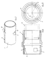
- FIGS. 1 and 2 each show the ends of two pipe parts 1, 1 'that come into connection. However, they also represent the two different ends of a single tube part.
- each of the tube parts 1, 1 ' has a sleeve 2 at one end.
- the sleeve 2 has a plurality of projections 3 on its inner circumference on the plug side, which point inwards protrude.
- an O-ring 4 connects to it as a seal.
- each tube part is essentially merely provided with recesses 5 which are arranged on the tube outer surface in accordance with the projections 4.
- the sleeve 2 is preferably designed as a plastic injection-molded part and firmly connected to a pipe section 6, which is produced in any length per se by extrusion from plastic. As can be seen in particular from FIGS. 1 and 2, the sleeve is not butt-welded to the tube piece 6, but rather encompasses it up to a stop 8. The welding takes place on the flanks which abut one another. This means there is no internal welding burr, which results in a smooth inner tube surface.
- connection area is essentially smooth and without projections (see FIG. 2), which facilitates the drawing in and / or blowing of lines into the protective pipe.
- connection between the pipe parts 1, 1 ' is to be released, one of the pipe parts must be rotated slightly about its axis, as indicated by the arrow in FIG. 2.
- a certain amount of rotational resistance has to be overcome in order to lift the projections 3 out of the recesses onto the adjacent tube circumference. This is a safeguard against unintentional loosening of the connection.
- the projections 3 or recesses 5 are Dimensioned so that a rotation through an angle of less than 30 ° is sufficient for loosening. Thanks to the elasticity of the plastic, this is also possible by hand, even when pipes are installed.
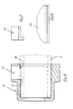
- FIGS. 3 to 5 from which the arrangement of the projections 3 and the recesses 5 results in detail.
- three recesses 5 or protrusions 3 are arranged on the circumference at angular intervals of 120.
- the recesses 5 are formed as incisions on the pipe outer surface, which form axial stops 10 against the associated pipe end. In the pipe circumferential direction, however, they pass continuously into the pipe outer surface, so that the projections 5 slide out of the incisions in the circumferential direction when a pipe part rotates, and the pipe parts can then be pulled apart.
- guides 12 are formed for a tool 13 for the mechanical removal of pipe material. This is shown in FIG. 7 in front view and in FIG. 8 in side view.
- the guides 12 run essentially tangentially to the tube circumference, so that the knife 13 is guided tangentially therein.
- a stop 14 is provided in the guides 12, which ensures the correct depth of the recess 5. In this way, the recesses 5 can be made at the right place on the construction site in a very short time so that the end of the pipe part can interact with the sleeve of a pipe part to be connected in the manner already described.
- the pipe parts 1, 1 engage in one another in the connected state without longitudinal play. It may now be desirable to design the connection so that it is able to accommodate tube dilation.
- the sleeve 2 can be made a little longer as a variant, so that the sleeve-free pipe end 1 can shift somewhat into the sleeve without the tensile connection being released.
- a preferred application of the pipe parts described is their use as protective pipes for transmission lines or power supply, which are laid underground. The same system can also be used for unpressurized sewage systems and for pressure lines (water supply) as well as for general line construction.
Applications Claiming Priority (2)
| Application Number | Priority Date | Filing Date | Title |
|---|---|---|---|
| CH2691/90 | 1990-08-20 | ||
| CH2691/90A CH682944A5 (de) | 1990-08-20 | 1990-08-20 | Rohr zum zugfesten Verbinden mit weiteren Rohren. |
Publications (2)
| Publication Number | Publication Date |
|---|---|
| EP0472002A1 true EP0472002A1 (fr) | 1992-02-26 |
| EP0472002B1 EP0472002B1 (fr) | 1995-07-05 |
Family
ID=4239411
Family Applications (1)
| Application Number | Title | Priority Date | Filing Date |
|---|---|---|---|
| EP91112563A Expired - Lifetime EP0472002B1 (fr) | 1990-08-20 | 1991-07-26 | Elément de tuyau comportant des organes de liaison |
Country Status (6)
| Country | Link |
|---|---|
| EP (1) | EP0472002B1 (fr) |
| AT (1) | ATE124770T1 (fr) |
| CH (1) | CH682944A5 (fr) |
| DE (1) | DE59105914D1 (fr) |
| DK (1) | DK0472002T3 (fr) |
| ES (1) | ES2073623T3 (fr) |
Cited By (4)
| Publication number | Priority date | Publication date | Assignee | Title |
|---|---|---|---|---|
| WO1996024003A1 (fr) * | 1995-02-03 | 1996-08-08 | Artform International Limited | Connecteurs |
| EP0742729A1 (fr) * | 1994-01-31 | 1996-11-20 | Mallinckrodt Medical, Inc. | Canule a accouplement rigide |
| US5678607A (en) * | 1986-01-15 | 1997-10-21 | Krywitsky; Lee A. | Reusable pipe union and pipe cap assembly for wide thermal cycling |
| EP1211452A1 (fr) * | 2000-11-20 | 2002-06-05 | Plastomer AG | Procédé de fabrication d'un tube en matière synthétique, notamment pour la protection de câbles et de conduits, et tube réalise selon ce procédé |
Citations (2)
| Publication number | Priority date | Publication date | Assignee | Title |
|---|---|---|---|---|
| DE2856520A1 (de) * | 1978-01-23 | 1979-07-26 | Cox Geelen Bv | Zylinderfoermiges rohrstueck z.b. aus aluminium fuer den zusammenbau von leitungen |
| CH647307A5 (en) * | 1982-08-12 | 1985-01-15 | Somo Societe Pour Les Metaux O | Pipe coupling |
-
1990
- 1990-08-20 CH CH2691/90A patent/CH682944A5/de not_active IP Right Cessation
-
1991
- 1991-07-26 DK DK91112563.1T patent/DK0472002T3/da active
- 1991-07-26 DE DE59105914T patent/DE59105914D1/de not_active Expired - Fee Related
- 1991-07-26 EP EP91112563A patent/EP0472002B1/fr not_active Expired - Lifetime
- 1991-07-26 AT AT91112563T patent/ATE124770T1/de not_active IP Right Cessation
- 1991-07-26 ES ES91112563T patent/ES2073623T3/es not_active Expired - Lifetime
Patent Citations (2)
| Publication number | Priority date | Publication date | Assignee | Title |
|---|---|---|---|---|
| DE2856520A1 (de) * | 1978-01-23 | 1979-07-26 | Cox Geelen Bv | Zylinderfoermiges rohrstueck z.b. aus aluminium fuer den zusammenbau von leitungen |
| CH647307A5 (en) * | 1982-08-12 | 1985-01-15 | Somo Societe Pour Les Metaux O | Pipe coupling |
Cited By (6)
| Publication number | Priority date | Publication date | Assignee | Title |
|---|---|---|---|---|
| US5678607A (en) * | 1986-01-15 | 1997-10-21 | Krywitsky; Lee A. | Reusable pipe union and pipe cap assembly for wide thermal cycling |
| EP0742729A1 (fr) * | 1994-01-31 | 1996-11-20 | Mallinckrodt Medical, Inc. | Canule a accouplement rigide |
| EP0742729A4 (fr) * | 1994-01-31 | 1997-08-13 | Mallinckrodt Medical Inc | Canule a accouplement rigide |
| WO1996024003A1 (fr) * | 1995-02-03 | 1996-08-08 | Artform International Limited | Connecteurs |
| GB2313641A (en) * | 1995-02-03 | 1997-12-03 | Artform Int Ltd | Connectors |
| EP1211452A1 (fr) * | 2000-11-20 | 2002-06-05 | Plastomer AG | Procédé de fabrication d'un tube en matière synthétique, notamment pour la protection de câbles et de conduits, et tube réalise selon ce procédé |
Also Published As
| Publication number | Publication date |
|---|---|
| CH682944A5 (de) | 1993-12-15 |
| ES2073623T3 (es) | 1995-08-16 |
| DK0472002T3 (da) | 1995-11-20 |
| DE59105914D1 (de) | 1995-08-10 |
| EP0472002B1 (fr) | 1995-07-05 |
| ATE124770T1 (de) | 1995-07-15 |
Similar Documents
| Publication | Publication Date | Title |
|---|---|---|
| DE2856064C2 (fr) | ||
| DE2524845C3 (de) | Lichtleiterkupplung zur Kupplung zweier Lichtleiter | |
| DE3330451C2 (de) | Vorrichtung zum schnellen und einfachen Verbinden durch Einstecken eines Endes eines von einem flüssigen Medium und/oder unter Druck stehenden Gas durchflossenen Fördermittels, wie beispielsweise einem Schlauch, Rohr od.dgl. mit einer Halteeinrichtung | |
| EP2724068B1 (fr) | Raccord de tuyau flexible et systéme de tuyau flexible correspondant | |
| DE3246327A1 (de) | Vorrichtung zur verbindung zweier rohrenden | |
| DE3101558A1 (de) | Vorrichtung zum halten von kabeln, leitungen, schlaeuchen oder dergleichen gegenstaende | |
| EP0332759A2 (fr) | Dispositif de fixation axiale pour la connexion d'éléments tubulaires | |
| EP3527866B1 (fr) | Raccord pour tuyau souple | |
| DE2162435A1 (de) | Schubsicherung von gummigedichteten rohrverbindungen | |
| DE2404555A1 (de) | Schnellkupplung fuer schlaeuche und starre rohre | |
| EP0510369A1 (fr) | Dispositif d'accouplement pour un système de tuyau flexible | |
| EP0327080A1 (fr) | Raccord pour tuyau | |
| EP0549860A1 (fr) | Dispositif d'accouplement de deux conduites, en particulier pour des conduites de carburant | |
| DE102006056663B4 (de) | Gewindeverbindung für Bohrgestänge | |
| EP0245233B1 (fr) | Pièce de raccordement, respectivement d'attache pour tuyaux et tuyaux flexibles | |
| EP0472002A1 (fr) | Elément de tuyau comportant des organes de liaison | |
| DE102017100357A1 (de) | Kupplungsanordnung für schraubkupplung | |
| CH581273A5 (en) | Snap connection between hose ends - has inner and outer sleeves with O-ring seal and finger with ridge and groove | |
| DE3221518C2 (de) | Fittinge zum automatischen Verbinden von Leitungen in pneumatischen oder hydraulischen Kreisen | |
| DE2906026C2 (de) | Rohrkupplung, insbesondere zum Anschluß von Kunststoffrohren | |
| DE3628543A1 (de) | Anschlussverbindungsstueck | |
| EP0170042A1 (fr) | Raccord | |
| DE3911258C2 (fr) | ||
| DE4239250A1 (de) | Einsteckkupplung für die Verbindung von zwei Kunststoffrohren | |
| DE3413792C1 (de) | Verbindung für miteinander verschraubbare Rohre |
Legal Events
| Date | Code | Title | Description |
|---|---|---|---|
| PUAI | Public reference made under article 153(3) epc to a published international application that has entered the european phase |
Free format text: ORIGINAL CODE: 0009012 |
|
| AK | Designated contracting states |
Kind code of ref document: A1 Designated state(s): AT BE DE DK ES FR GB GR IT NL |
|
| 17P | Request for examination filed |
Effective date: 19920819 |
|
| 17Q | First examination report despatched |
Effective date: 19930825 |
|
| GRAA | (expected) grant |
Free format text: ORIGINAL CODE: 0009210 |
|
| STAA | Information on the status of an ep patent application or granted ep patent |
Free format text: STATUS: THE PATENT HAS BEEN GRANTED |
|
| AK | Designated contracting states |
Kind code of ref document: B1 Designated state(s): AT BE DE DK ES FR GB GR IT NL |
|
| REF | Corresponds to: |
Ref document number: 124770 Country of ref document: AT Date of ref document: 19950715 Kind code of ref document: T |
|
| ITF | It: translation for a ep patent filed |
Owner name: MARCHI & MITTLER S.R.L. |
|
| ET | Fr: translation filed | ||
| GBT | Gb: translation of ep patent filed (gb section 77(6)(a)/1977) |
Effective date: 19950704 |
|
| REF | Corresponds to: |
Ref document number: 59105914 Country of ref document: DE Date of ref document: 19950810 |
|
| REG | Reference to a national code |
Ref country code: ES Ref legal event code: FG2A Ref document number: 2073623 Country of ref document: ES Kind code of ref document: T3 |
|
| REG | Reference to a national code |
Ref country code: GR Ref legal event code: FG4A Free format text: 3016745 |
|
| REG | Reference to a national code |
Ref country code: DK Ref legal event code: T3 |
|
| PLBE | No opposition filed within time limit |
Free format text: ORIGINAL CODE: 0009261 |
|
| 26N | No opposition filed | ||
| PGFP | Annual fee paid to national office [announced via postgrant information from national office to epo] |
Ref country code: GR Payment date: 19990630 Year of fee payment: 9 |
|
| PGFP | Annual fee paid to national office [announced via postgrant information from national office to epo] |
Ref country code: BE Payment date: 19990702 Year of fee payment: 9 |
|
| PGFP | Annual fee paid to national office [announced via postgrant information from national office to epo] |
Ref country code: ES Payment date: 19990708 Year of fee payment: 9 |
|
| PGFP | Annual fee paid to national office [announced via postgrant information from national office to epo] |
Ref country code: GB Payment date: 19990721 Year of fee payment: 9 |
|
| PGFP | Annual fee paid to national office [announced via postgrant information from national office to epo] |
Ref country code: DK Payment date: 19990723 Year of fee payment: 9 |
|
| PGFP | Annual fee paid to national office [announced via postgrant information from national office to epo] |
Ref country code: NL Payment date: 19990730 Year of fee payment: 9 |
|
| PG25 | Lapsed in a contracting state [announced via postgrant information from national office to epo] |
Ref country code: GB Free format text: LAPSE BECAUSE OF NON-PAYMENT OF DUE FEES Effective date: 20000726 Ref country code: DK Free format text: LAPSE BECAUSE OF NON-PAYMENT OF DUE FEES Effective date: 20000726 |
|
| PG25 | Lapsed in a contracting state [announced via postgrant information from national office to epo] |
Ref country code: ES Free format text: LAPSE BECAUSE OF NON-PAYMENT OF DUE FEES Effective date: 20000727 |
|
| PG25 | Lapsed in a contracting state [announced via postgrant information from national office to epo] |
Ref country code: GR Free format text: LAPSE BECAUSE OF NON-PAYMENT OF DUE FEES Effective date: 20000731 Ref country code: BE Free format text: LAPSE BECAUSE OF NON-PAYMENT OF DUE FEES Effective date: 20000731 |
|
| BERE | Be: lapsed |
Owner name: JANSEN A.G. Effective date: 20000731 |
|
| PG25 | Lapsed in a contracting state [announced via postgrant information from national office to epo] |
Ref country code: NL Free format text: LAPSE BECAUSE OF NON-PAYMENT OF DUE FEES Effective date: 20010201 |
|
| GBPC | Gb: european patent ceased through non-payment of renewal fee |
Effective date: 20000726 |
|
| REG | Reference to a national code |
Ref country code: DK Ref legal event code: EBP |
|
| NLV4 | Nl: lapsed or anulled due to non-payment of the annual fee |
Effective date: 20010201 |
|
| PGFP | Annual fee paid to national office [announced via postgrant information from national office to epo] |
Ref country code: AT Payment date: 20030717 Year of fee payment: 13 |
|
| PGFP | Annual fee paid to national office [announced via postgrant information from national office to epo] |
Ref country code: DE Payment date: 20030730 Year of fee payment: 13 |
|
| PGFP | Annual fee paid to national office [announced via postgrant information from national office to epo] |
Ref country code: FR Payment date: 20030731 Year of fee payment: 13 |
|
| REG | Reference to a national code |
Ref country code: ES Ref legal event code: FD2A Effective date: 20010810 |
|
| PG25 | Lapsed in a contracting state [announced via postgrant information from national office to epo] |
Ref country code: AT Free format text: LAPSE BECAUSE OF NON-PAYMENT OF DUE FEES Effective date: 20040726 |
|
| PG25 | Lapsed in a contracting state [announced via postgrant information from national office to epo] |
Ref country code: DE Free format text: LAPSE BECAUSE OF NON-PAYMENT OF DUE FEES Effective date: 20050201 |
|
| PG25 | Lapsed in a contracting state [announced via postgrant information from national office to epo] |
Ref country code: FR Free format text: LAPSE BECAUSE OF NON-PAYMENT OF DUE FEES Effective date: 20050331 |
|
| REG | Reference to a national code |
Ref country code: FR Ref legal event code: ST |
|
| PG25 | Lapsed in a contracting state [announced via postgrant information from national office to epo] |
Ref country code: IT Free format text: LAPSE BECAUSE OF NON-PAYMENT OF DUE FEES;WARNING: LAPSES OF ITALIAN PATENTS WITH EFFECTIVE DATE BEFORE 2007 MAY HAVE OCCURRED AT ANY TIME BEFORE 2007. THE CORRECT EFFECTIVE DATE MAY BE DIFFERENT FROM THE ONE RECORDED. Effective date: 20050726 |