EP0468385A2 - Procédé pour la rectification tangentielle des pièces à usiner en coupe transversale non circulaires - Google Patents
Procédé pour la rectification tangentielle des pièces à usiner en coupe transversale non circulaires Download PDFInfo
- Publication number
- EP0468385A2 EP0468385A2 EP91112171A EP91112171A EP0468385A2 EP 0468385 A2 EP0468385 A2 EP 0468385A2 EP 91112171 A EP91112171 A EP 91112171A EP 91112171 A EP91112171 A EP 91112171A EP 0468385 A2 EP0468385 A2 EP 0468385A2
- Authority
- EP
- European Patent Office
- Prior art keywords
- steps
- workpiece
- axis
- contour
- grinding
- Prior art date
- Legal status (The legal status is an assumption and is not a legal conclusion. Google has not performed a legal analysis and makes no representation as to the accuracy of the status listed.)
- Withdrawn
Links
Images


Classifications
-
- B—PERFORMING OPERATIONS; TRANSPORTING
- B24—GRINDING; POLISHING
- B24B—MACHINES, DEVICES, OR PROCESSES FOR GRINDING OR POLISHING; DRESSING OR CONDITIONING OF ABRADING SURFACES; FEEDING OF GRINDING, POLISHING, OR LAPPING AGENTS
- B24B19/00—Single-purpose machines or devices for particular grinding operations not covered by any other main group
- B24B19/08—Single-purpose machines or devices for particular grinding operations not covered by any other main group for grinding non-circular cross-sections, e.g. shafts of elliptical or polygonal cross-section
- B24B19/12—Single-purpose machines or devices for particular grinding operations not covered by any other main group for grinding non-circular cross-sections, e.g. shafts of elliptical or polygonal cross-section for grinding cams or camshafts
- B24B19/125—Single-purpose machines or devices for particular grinding operations not covered by any other main group for grinding non-circular cross-sections, e.g. shafts of elliptical or polygonal cross-section for grinding cams or camshafts electrically controlled, e.g. numerically controlled
-
- B—PERFORMING OPERATIONS; TRANSPORTING
- B24—GRINDING; POLISHING
- B24B—MACHINES, DEVICES, OR PROCESSES FOR GRINDING OR POLISHING; DRESSING OR CONDITIONING OF ABRADING SURFACES; FEEDING OF GRINDING, POLISHING, OR LAPPING AGENTS
- B24B19/00—Single-purpose machines or devices for particular grinding operations not covered by any other main group
- B24B19/08—Single-purpose machines or devices for particular grinding operations not covered by any other main group for grinding non-circular cross-sections, e.g. shafts of elliptical or polygonal cross-section
Definitions
- the invention relates to a method for the peripheral grinding of radially non-circular workpieces, in which the workpiece is rotated about a first axis and a grinding wheel is fed along a second axis, which includes an angle of preferably 90 ° with the first axis, with the workpiece on Its surface, starting from a raw contour, is removed along spiral-like paths of an engagement point in a plurality of steps corresponding to one revolution of the workpiece in each case to intermediate contours and finally to a finished contour by rotating the workpiece and the grinding wheel in a predetermined manner as a function of data records are delivered, a new data record for the subsequent rotation of the workpiece being called up each time an intermediate contour is reached and in which a predetermined absolute dimension of the workpiece is continuously measured and a deviation from a target value is determined.
- CNC Numerically controlled
- CNC Numerically controlled
- the workpieces are clamped and rotated about their longitudinal axis (so-called C axis) by means of a controllable workpiece turning device.
- the grinding wheel is arranged on a grinding carriage which can be advanced along a further axis (so-called X-axis) towards the axis of rotation of the workpiece.
- the C-axis and the X-axis are usually perpendicular to each other.
- the desired circumferential profile of the workpiece e.g. the cam shape or the polygon shape are now generated in that the workpiece is rotated around the C axis in predetermined angular increments as a function of one another and at the same time the grinding wheel is adjusted linearly along the X axis.
- These two mutually coordinated movements describe the desired profile of the workpiece in the so-called "path operation", while in the so-called “infeed operation” a further infeed movement is superimposed which corresponds to the desired material removal.
- data records are stored in the control of the grinding machine. These data records assign a certain linear setting of the X axis to each angular position of the C axis, the values of the data records being matched to one another in such a way that the desired circumferential profile is created, taking into account both the "rail operation” and the “delivery operation” ".
- Workpieces of the type of interest here are delivered as blanks for carrying out such processes, i.e. as workpieces that still have a considerable allowance compared to the desired finished size, which must be removed with the respective process.
- the overall measurement i.e. the geometrical distance of the raw contour from the desired target contour, generally greater than the amount of material that can be removed in one machining step
- the known methods are usually carried out in several steps in succession. For example, a few roughing steps with a relatively large infeed are usually carried out first, followed by a few finishing steps with a correspondingly smaller infeed, until the finished workpiece is finally extended, i.e. is clamped out of the workpiece holder.
- the point of engagement of the grinding wheel on the workpiece is guided along a spiral path which begins at a first point of engagement of the grinding wheel on the raw contour of the still unprocessed workpiece and finally at an end point of the finished contour of the finished workpiece ends.
- a first disturbing influence can result from the fact that a workpiece clamped at the ends, for example a long thin shaft, radially evades the grinding wheel which is in contact. Another disturbing influence consists in thermal length changes in components of the machine tool and also in the workpiece itself. Another disturbing influence results from dynamic tracking errors Learn if the grinding machine has to move relatively large masses (grinding slides) relatively quickly to perform a non-circular grinding process. Finally, there are also interference from wear of the grinding wheel, changes in position when clamping and unclamping, and the like.
- the errors resulting from these interferences are divided into the so-called form errors and the so-called dimensional errors.
- shape errors only the deviation from the ideally specified shape is taken into account, without absolute dimensions playing a role.
- dimensional errors only the absolute dimensions of certain characteristic points of the generated profile are checked, while the form accuracy is otherwise not taken into account.
- This method thus has the essential advantage that a correction of the dimensional errors can be carried out at least for the other cams of the camshaft in one and the same clamping.
- the first cam was still ground with the uncorrected data records.
- this known method is not applicable to such non-circular workpieces in which only a single non-circular profile is provided on the workpiece. This is e.g. the case for polygon waves or polygon connections with outer or inner polygon.
- the invention is therefore based on the object of developing a method of the type mentioned in such a way that machining errors are recognized, monitored and evaluated for the control of the machine tool from the first engagement of the grinding wheel on the workpiece, so that the ground workpieces are true to scale.
- This object is achieved in that the deviation is compared with threshold values and that a predetermined number of steps are skipped when the threshold values are undershot.
- the method according to the invention uses a regulated method in which the dimensions of the workpiece are monitored by continuous measurement, in that a comparison with a setpoint takes place. If the target value provided for the respective machining or machining phase has been reached, the machining is stopped, with the result that a workpiece is always produced which has exactly the desired dimensions.
- the method according to the invention therefore makes it possible for the first time to grind non-circular workpieces with precise dimensions even during the very first machining. But also for workpieces, e.g. Camshafts, in which the same non-circular profiles are to be ground at several points on the workpiece, it is possible with the method according to the invention, already at the first machining point, e.g. on the first cam to create an accurate profile.
- workpieces e.g. Camshafts
- the method according to the invention already at the first machining point, e.g. on the first cam to create an accurate profile.
- a first plurality of roughing steps and a subsequent second plurality of finishing steps are provided, and all further roughing steps are skipped if the threshold value is undershot during a roughing step.
- This measure has the advantage that when machining in several phases (roughing / finishing), during the course of one of the several machining phases, the attainment of an intermediate target value is monitored in order to immediately set the end of this machining phase.
- the method according to the invention can thus also be used in subsequent machining phases or when machining workpieces that are machined with only one type of machining.
- a finite amount of delivery is specified during some of the plurality of steps and the amount is dimensioned differently for successive steps.
- the amount of delivery for successive steps can decrease.
- This measure has the advantage that, depending on the circumferential profile, material or type of grinding wheel, the oversize to be removed can be individually determined for successive processing steps.
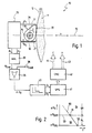
- 10 designates an extremely schematically illustrated grinding machine.
- the grinding machine 10 comprises a grinding wheel 11, which rotates in a direction indicated by 12 about an axis, not shown in FIG. 1.
- the grinding wheel 11 is adjustable along a linear first axis 13, the so-called X axis.
- the grinding wheel 11 is arranged on a grinding carriage, not shown in FIG. 1, which can be displaced in a conventional manner in the direction of the first axis 13, likewise likewise not shown in FIG. 1 for the sake of clarity.
- a cam 15 is shown in FIG. 1 as an example of a radially out-of-round workpiece, as can be machined using the method according to the invention.
- the cam 15 has a base circle portion 16, i.e. an area with a constant radius, and also an elevation section 17, an area in which the cam 15 is radially out of round.
- the cam 15 is part of a camshaft that is clamped about its longitudinal axis in a second axis 18 of the grinding machine 10.
- the second axis 18 is an axis of rotation, as indicated by an arrow in FIG. 1. In practice it is referred to as the C axis.
- engagement point 20 is of course to be understood as a linear contact of the grinding wheel 11 on the cam 15 perpendicular to the plane of the drawing in FIG. 1.
- the second axis 18 is usually perpendicular to the first axis 13, but the two axes can also form a finite angle include another size.
- the cam 15 is rotated about the second axis 18 in predetermined angular steps, and the grinding wheel 11 is simultaneously reciprocated along the first axis 13 in a predetermined manner. In this way, the desired profile is described while the engagement point 20 is moving, and at the same time the required delivery is set.
- the grinding machine 10 of FIG. 1 corresponds to the prior art, as was initially recognized.
- the grinding machine 10 also has a length measuring device 25, which is arranged in a fixed position in the vicinity of the cam 15 and works during the machining process.
- the length measuring device 25 has two measuring beaks 26, 27 which, in the illustration in FIG. 1, rest against the cam 15 from above and from below.
- the measuring beaks 26, 27 are able to follow the cam shape, as indicated by double arrows in FIG. 1. They each measure the current radius R.
- the upper measuring beak 26, for example measures a value Ri which almost corresponds to the maximum survey value of the cam 15, while the lower measuring beak 27 measures a value R 2 , which equals the base circle radius R G of the cam 15 in the base circle section 16.
- the measured values determined by the measuring beaks 26, 27 are forwarded from the outputs of the length measuring device 25 to a minimum selection 30.
- the minimum selection 30 only forwards the smaller of the two measured values R 1 or R 2 . Since the base circle section 16 sweeps over a circumferential angle of more than 180 °, at least one of the measuring beaks 26 or 27 bears against the base circle section 16, which also represents the area of the minimum radius.
- this value R Gist is now compared with a target value R Gsoll , which is supplied to the comparator 35 by a controller via a terminal 36.
- the comparator 35 thus determines the deviation of the actual value R Gist from the target value R Gsoll , and the resulting deviation is designated AR G in FIG. 1.
- the deviation AR G is now fed to a threshold value stage 40 connected downstream of the comparator 35.
- threshold level 40 For an explanation of the threshold level 40, reference may be made here to FIG. 2.
- the deviation AR G of the actual value R Gist from the target value R Gsoll of the desired finished contour decreases with progressive processing, ie progressive time t, as shown with a curve 50 in FIG. 2.
- the course 50 first reaches a point 51 and then a point 52 in the course of the machining.
- the point 51 lies on a dividing line 53 which separates a roughing area 54 from a finishing area 55, the machining steps of the roughing in FIG. 2 and in the following figures with SR and the finishing with SL are characterized.
- a threshold value AR GSR is stored in the comparator 40, while the end of the finishing area 55 is characterized by a threshold value AR GSL , which is preferably zero.
- the threshold value stage 40 If the course 50 of the deviation ⁇ R G reaches the first point 51, that is to say the end of the roughing area 54 has been reached, the threshold value stage 40 generates a first signal Si, while when the point 52 is reached the end of the finishing area 55 turns on corresponding signal S 2 is generated.
- the signals S 1 and S 2 are passed from the output of the threshold stage 40 to an input of a programmable logic controller 41, which in turn controls a numerical control device 42 of the grinding machine 10.
- the numerical control device 42 is connected to data outputs 43 and 44 for the movement units of the X-axis, ie the first axis 13, and the C-axis, ie the second axis 18.
- Fig. 3 shows an enlarged view of the cam 15 in side view.
- the cam 15 is shown in the unprocessed state, so that a raw contour is present on the circumference with 60.
- 61 denotes an intermediate contour that is generated as an intermediate result in the course of the grinding process.
- 62 finally denotes a finished contour, i.e. the contour of the finished cam with the desired dimensions.
- FIG. 3 and also that of the following FIG. 4 is to be understood only extremely schematically and that the dimensions given are exaggerated for the purpose of illustration. It is further understood that a large number of intermediate contours 61 are present between the raw contour 60 and the finished contour 62, of which only one is shown for the sake of clarity.
- 63 denotes a starting point at which the grinding wheel attacks the blank shown for the first time, as symbolized by an arrow 64.
- the current engagement point which was designated by 20 in FIG. 1
- follows a spiral-like path 65 which moves away from the raw contour 60 with increasing infeed and approaches the first intermediate contour 61 in order to reach an intermediate point 66 there.
- the intermediate point 66 has a radial distance from the starting point 63, which corresponds to the oversize between the raw contour 60 and the first intermediate contour 65.
- Fig. 4 shows corresponding relationships in the case of a polygon profile 70, as it is e.g. is used for torque connections between shafts and hubs or spindles and tools.
- 71 denotes a raw contour, 72 an intermediate contour and 73 a finished contour.
- the grinding wheel begins its processing at a starting point 74, as symbolized by an arrow 75, and then again follows a spiral path 76 to an intermediate point 77 on the intermediate contour 72.
- FIG. 5 shows a diagram which shows the dependence of the infeed A X set for successive steps on the time t during a machining process.
- a staircase curve 80 can be clearly seen in FIG. 5, which means that the infeed from processing step to processing step, i.e. is changed in stages from revolution to revolution of the workpiece.
- step by step is to be understood in such a way that the infeed during a processing step, i.e. during one revolution of the workpiece, can only be adjusted to the extent that the amount of infeed desired for the machining step over a relatively short period of time, i.e. the rotation of the workpiece is set over a very small angular range. So it is e.g. in the case of cam grinding, it is known to set the entire infeed by moving the grinding wheel 11 when the grinding wheel is in engagement with the base circle section 16 of the cam 15.
- the infeed can be set continuously or quasi-continuously, in which case a continuous calculation of the infeed increments with the coordinates of the profile to be generated must then be carried out over the entire circumference of the workpiece.
- 5 again shows areas 54 'and 55' for the roughing SR and the finishing SL. It can also be seen that the amount of the infeed AX set for a processing step is not constant. Preferably, the infeed desired for successive machining steps is set ever smaller and naturally considerably larger during roughing than during finishing. 5 shows as an example an infeed amount A, X for the first machining step, ie the first rotation of the workpiece, a smaller infeed amount A 4 X for the fourth machining step, still during the roughing SR, and finally a much smaller infeed amount ⁇ oX which already affects a processing step during the SL finishing.
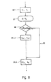
- FIG. 6 shows in a schematic form how data records are generated for successive processing steps.
- Fig. 6, 85 denotes a profile memory that contains a so-called basic profile.
- This basic profile can be stored in Cartesian coordinates, in polar coordinates or in the coordinates of the two axes 13, 18. If necessary, a coordinate transformation can be carried out between these various coordinates by methods known per se.
- an infeed A X for successive machining steps can be stored in an infeed memory 86.
- the basic profile stored in the profile memory 85 can now be converted for each of the successive processing steps, so that a second profile memory 88 is created in which modified profiles C * , X * are stored.
- this takes place in that the C coordinates are adopted unchanged from the first profile memory 85, while the X coordinates are only changed additively by the desired delivery amount AX for the respective processing step.
- 91/1 ..., 91/4, 91/5 ..., 91 / n denote blocks which correspond to the individual machining steps or data records C, X in the roughing area 54 ".
- 91 / In contrast, n + 1 ..., 91 / n + 3, 91 / n + 4 ..., 91 / n + m denote blocks or data records for the machining steps in the finishing area 55 ".
- the numbers n and m for the roughing and finishing steps are so large that they are larger than the number of machining steps required for the respective workpiece in the worst case. In other words, this means that if one would process all n roughing steps, all m finishing steps, even under the most unfavorable conditions, a workpiece would always be produced whose final dimensions are smaller than the desired ones.
- the signal S 1 is generated by the threshold value stage 40.
- the signal S 1 in the programmable logic controller 41 and the subsequent CNC control unit 42 has the consequence that a jump 93 takes place in the flow diagram 90 of FIG. 7, which immediately leads to the end of the process sequence after the fourth roughing step 91/4 has been processed Roughing area 51 "continues, that is to say skips the further roughing steps 91/5 ..., 91 / n which are provided per se. The process is then immediately continued with the finishing steps 91 / n + 1 ....
- a decision block 98 now compares whether this deviation ⁇ i R G is even greater than the target value ⁇ R GSR . If so, go to the following roughing step 91 / i + 1. If this is not the case, ie the threshold value ⁇ R GSR has already been reached, the jump 93 to the first finishing step 91 / n is initiated.
- FIGS. 7 and 8 are only one example of several possibilities.
- a very large number of blocks 91 which is greater than the maximum required number
- a smaller, limited number of blocks can also be provided, which in the end is designed like a loop with any number of repetitions of the last step in each case.
- This last step in each case would have to be provided with a relatively small delivery amount and processed until the comparator 35 with the subsequent threshold value stage 40 recognizes that a limit value has been reached, in order then to suppress further repetitions.
Landscapes
- Engineering & Computer Science (AREA)
- Mechanical Engineering (AREA)
- Grinding And Polishing Of Tertiary Curved Surfaces And Surfaces With Complex Shapes (AREA)
Applications Claiming Priority (2)
| Application Number | Priority Date | Filing Date | Title |
|---|---|---|---|
| DE4023587A DE4023587C2 (de) | 1990-07-25 | 1990-07-25 | Verfahren zum meßgesteuerten Umfangsschleifen von radial unrunden Werkstücken |
| DE4023587 | 1990-07-25 |
Publications (2)
| Publication Number | Publication Date |
|---|---|
| EP0468385A2 true EP0468385A2 (fr) | 1992-01-29 |
| EP0468385A3 EP0468385A3 (en) | 1992-03-04 |
Family
ID=6410970
Family Applications (1)
| Application Number | Title | Priority Date | Filing Date |
|---|---|---|---|
| EP19910112171 Withdrawn EP0468385A3 (en) | 1990-07-25 | 1991-07-20 | Method for the circumferential grinding of radial non-circular works |
Country Status (4)
| Country | Link |
|---|---|
| US (1) | US5251405A (fr) |
| EP (1) | EP0468385A3 (fr) |
| JP (1) | JPH04250965A (fr) |
| DE (1) | DE4023587C2 (fr) |
Cited By (1)
| Publication number | Priority date | Publication date | Assignee | Title |
|---|---|---|---|---|
| WO2021069390A1 (fr) * | 2019-10-12 | 2021-04-15 | KAPP NILES GmbH & Co. KG | Procédé de meulage d'une pièce avec une denture ou un profil |
Families Citing this family (21)
| Publication number | Priority date | Publication date | Assignee | Title |
|---|---|---|---|---|
| IT1273865B (it) * | 1994-12-27 | 1997-07-11 | Marposs Spa | Dispositivo di controllo per una macchina utensile microfinitrice |
| JP3490534B2 (ja) * | 1995-03-23 | 2004-01-26 | オークマ株式会社 | 非円形工作物の研削加工方法及び装置 |
| US5733093A (en) * | 1995-12-22 | 1998-03-31 | Robodyne Corporation | Stack tube feeder |
| DE19622767A1 (de) * | 1996-06-07 | 1997-12-11 | Bayerische Motoren Werke Ag | Schleifverfahren für eine rechnergestützte Werkzeugmaschine, insbesondere Schleifmaschine zum Formschleifen, vor allem von Steuernocken einer Nockenwelle |
| DE19626189A1 (de) * | 1996-06-29 | 1998-01-02 | Schaudt Maschinenbau Gmbh | Verfahren zum Schleifen rotierender Werkstücke |
| CA2220776A1 (fr) * | 1996-11-13 | 1998-05-13 | Allen Sommers | Systeme de chargement de rectifieuse excentrique |
| JP2898279B1 (ja) * | 1998-05-26 | 1999-05-31 | 株式会社ゼクセル | 研削加工装置 |
| GB2346574B (en) * | 1999-02-03 | 2001-09-19 | Unova Uk Ltd | Angle head grinding method and apparatus |
| EP1224057B1 (fr) * | 1999-10-27 | 2003-07-09 | Unova U.K. Limited | Procede de rectification de maneton |
| JP4065185B2 (ja) * | 2002-11-26 | 2008-03-19 | 武蔵精密工業株式会社 | 非円形回転体ワークの研削方法及びその装置 |
| DE102004009352B4 (de) * | 2004-02-26 | 2006-01-19 | Thyssen Krupp Automotive Ag | Vorrichtung zum Herstellen einer Fertigkontur eines Werkstücks durch Schleifen und Verfahren dazu |
| JP5228554B2 (ja) * | 2008-03-19 | 2013-07-03 | 株式会社ジェイテクト | 非真円箇所研削盤における工作物異常回転検出装置 |
| JP5412130B2 (ja) * | 2009-02-16 | 2014-02-12 | 中村留精密工業株式会社 | 板状ワークの外周研削装置 |
| DE102009009222B4 (de) * | 2009-02-17 | 2012-03-29 | Emag Holding Gmbh | Verfahren und Schleifmaschine zum Schleifen von stabförmigen Werkstücken |
| CN102049731B (zh) * | 2010-09-30 | 2012-11-28 | 常州工学院 | 对盘形凸轮进行精确轮廓测量及精确加工的方法 |
| DE102011115254A1 (de) * | 2011-09-27 | 2013-03-28 | Fritz Studer Ag | Werkzeugmaschine und Verfahren zur Vermessung eines Werkstücks |
| DE102012110673B4 (de) * | 2012-11-07 | 2014-05-15 | Fritz Studer Ag | Werkzeugmaschine und Verfahren zur Vermessung eines Werkstücks |
| CN103111928A (zh) * | 2013-01-10 | 2013-05-22 | 贵州黎阳航空动力有限公司 | 一种凸轮的数控座标磨加工方法 |
| JP6658178B2 (ja) * | 2016-03-23 | 2020-03-04 | 株式会社ジェイテクト | カム研削装置、およびカム研削方法 |
| DE102021108073A1 (de) * | 2021-03-30 | 2022-10-06 | KAPP NILES GmbH & Co. KG | Verfahren zum Schleifen eines Werkstücks mit einer Verzahnung oder einem Profil |
| CN114603403B (zh) * | 2022-03-15 | 2023-05-26 | 先导薄膜材料(广东)有限公司 | 一种菱形角度溅射靶材的加工方法 |
Citations (4)
| Publication number | Priority date | Publication date | Assignee | Title |
|---|---|---|---|---|
| DE2114960A1 (de) * | 1970-03-28 | 1971-10-14 | Toyoda Koki K K , Kariya, Aichi (Japan) | Verfahren und Schleifmaschine zum Schleifen einer Vielzahl von Bearbei tungsstellen eines Werkstucks mit einer Schleifscheibe |
| DE2427244B2 (de) * | 1974-06-06 | 1976-12-30 | Diskus Werke Frankfurt Am Main Ag, 6000 Frankfurt | Schleifscheiben-zustellvorrichtung fuer schleifmaschinen |
| DE2937313A1 (de) * | 1978-09-15 | 1980-03-27 | Meseltron Sa | Verfahren zum messgesteuerten laengsschleifen |
| US4505074A (en) * | 1981-05-21 | 1985-03-19 | Seiko Seiki Kabushiki Kaisha | Grinding machine control system for intermittently measuring workpiece size |
Family Cites Families (6)
| Publication number | Priority date | Publication date | Assignee | Title |
|---|---|---|---|---|
| US3746956A (en) * | 1971-04-02 | 1973-07-17 | Toyoda Machine Works Ltd | Tape-reading control system for repeat-processing cycles of traverse cutting |
| JPS58192743A (ja) * | 1982-04-29 | 1983-11-10 | Toyoda Mach Works Ltd | カム研削方法 |
| JPS6090667A (ja) * | 1983-10-20 | 1985-05-21 | Toyoda Mach Works Ltd | カム研削方法 |
| DE3529099A1 (de) * | 1985-08-14 | 1987-02-19 | Fortuna Werke Maschf Ag | Verfahren und vorrichtung zum spanabhebenden bearbeiten einer oberflaeche von profilen mit einer von einer kreisform abweichenden kontur, insbesondere nockenwellen |
| JPH0698554B2 (ja) * | 1986-09-22 | 1994-12-07 | 豊田工機株式会社 | 数値制御加工装置 |
| DE3702594C3 (de) * | 1987-01-29 | 1995-04-06 | Fortuna Werke Maschf Ag | Verfahren und Vorrichtung zum Schleifen von Nocken an Nockenwellen |
-
1990
- 1990-07-25 DE DE4023587A patent/DE4023587C2/de not_active Expired - Fee Related
-
1991
- 1991-07-20 EP EP19910112171 patent/EP0468385A3/de not_active Withdrawn
- 1991-07-24 US US07/734,964 patent/US5251405A/en not_active Expired - Fee Related
- 1991-07-25 JP JP3207313A patent/JPH04250965A/ja active Pending
Patent Citations (4)
| Publication number | Priority date | Publication date | Assignee | Title |
|---|---|---|---|---|
| DE2114960A1 (de) * | 1970-03-28 | 1971-10-14 | Toyoda Koki K K , Kariya, Aichi (Japan) | Verfahren und Schleifmaschine zum Schleifen einer Vielzahl von Bearbei tungsstellen eines Werkstucks mit einer Schleifscheibe |
| DE2427244B2 (de) * | 1974-06-06 | 1976-12-30 | Diskus Werke Frankfurt Am Main Ag, 6000 Frankfurt | Schleifscheiben-zustellvorrichtung fuer schleifmaschinen |
| DE2937313A1 (de) * | 1978-09-15 | 1980-03-27 | Meseltron Sa | Verfahren zum messgesteuerten laengsschleifen |
| US4505074A (en) * | 1981-05-21 | 1985-03-19 | Seiko Seiki Kabushiki Kaisha | Grinding machine control system for intermittently measuring workpiece size |
Cited By (1)
| Publication number | Priority date | Publication date | Assignee | Title |
|---|---|---|---|---|
| WO2021069390A1 (fr) * | 2019-10-12 | 2021-04-15 | KAPP NILES GmbH & Co. KG | Procédé de meulage d'une pièce avec une denture ou un profil |
Also Published As
| Publication number | Publication date |
|---|---|
| DE4023587C2 (de) | 1993-11-18 |
| JPH04250965A (ja) | 1992-09-07 |
| EP0468385A3 (en) | 1992-03-04 |
| DE4023587A1 (de) | 1992-02-06 |
| US5251405A (en) | 1993-10-12 |
Similar Documents
| Publication | Publication Date | Title |
|---|---|---|
| DE4023587C2 (de) | Verfahren zum meßgesteuerten Umfangsschleifen von radial unrunden Werkstücken | |
| EP0543079B1 (fr) | Méthode à commande numérique pour meuler la came d'un arbre à cames | |
| DE69120271T2 (de) | Verfahren und Vorrichtung zum Einrichten von Werkstücken auf Maschinen zur Zahnradherstellung. | |
| DE69718520T2 (de) | Verfahren zum Schleifen von Verbundwerkstücken | |
| EP1938162A1 (fr) | Procede et dispositif pour compenser des ecarts de position et de forme | |
| EP2923790B1 (fr) | Procédé de meulage de roues coniques dans un procédé de rectification en bout | |
| WO2005084886A1 (fr) | Dispositif de production d'un profil fini d'une piece par rectification et procede correspondant | |
| DE2832646A1 (de) | Verfahren und vorrichtung zum maschinellen bearbeiten von nockenprofilen | |
| DE4036283C2 (de) | Verfahren und Vorrichtung zur Steuerung von Zylinderschleifmaschinen | |
| EP0212338B1 (fr) | Procédé pour l'usinage de la surface d'une came | |
| DE2918249A1 (de) | Maschine zum vorzugsweise spanenden umfangsbearbeiten von unrunden werkstuecken, insbesondere kolbenringen | |
| DE3821412A1 (de) | Verfahren zum korrigieren der fehlausrichtung eines werkstuecks in einer nc-werkzeugmaschine | |
| DE1954845B2 (de) | Vorrichtung zur optimalen anpassung einer numerisch gesteuerten werkzeugmaschine an den bearbeitungsvorgang eines werkstueckes | |
| DE3914549C2 (fr) | ||
| DE69715464T2 (de) | Verfahren und Vorrichtung zum konzentrischen Schleifen von zylindrischen Werkstückbereichen | |
| EP3820646A1 (fr) | Procédé de rodage et machine d'usinage pour le rodage de contours | |
| DE69712222T2 (de) | Verfahren zur steuerung einer werkzeugmaschine | |
| DE102012012174A1 (de) | Verfahren zum Kompensieren einer Werkzeugrundlaufabweichung | |
| DE69323795T2 (de) | Numerische Steuerungsvorrichtung zur Werkzeugführung entlang nicht-orthogonaler mechanischer Achsen | |
| DE4330469C2 (de) | Verfahren zum Steuern einer Werkzeugmaschine mit mehreren Schlitten | |
| DE10354690A1 (de) | Verfahren zum Bearbeiten von Konturen an Werkstücken durch spanende Bearbeitung sowie Vorrichtung zur Durchführung eines solchen Verfahrens | |
| DE19919147B4 (de) | Verfahren zur Ermittlung eines Konturfehlers und Verfahren zur Kontrolle einer korrekten Sollwertvorgabe | |
| EP0811897B1 (fr) | Procédé de meulage pour une machine outil assistée par ordinateur, en particulier pour le meulage de forme, en premier lieu le meulage des cames d'un arbre à cames | |
| CH631646A5 (en) | Process for the external cylindrical grinding of a plurality of diameters of a workpiece in a mount | |
| EP0334345A2 (fr) | Procédé pour rectifier les cames d'un arbre à cames |
Legal Events
| Date | Code | Title | Description |
|---|---|---|---|
| PUAI | Public reference made under article 153(3) epc to a published international application that has entered the european phase |
Free format text: ORIGINAL CODE: 0009012 |
|
| PUAL | Search report despatched |
Free format text: ORIGINAL CODE: 0009013 |
|
| AK | Designated contracting states |
Kind code of ref document: A2 Designated state(s): CH DE FR GB IT LI |
|
| AK | Designated contracting states |
Kind code of ref document: A3 Designated state(s): CH DE FR GB IT LI |
|
| 17P | Request for examination filed |
Effective date: 19920826 |
|
| 17Q | First examination report despatched |
Effective date: 19930907 |
|
| STAA | Information on the status of an ep patent application or granted ep patent |
Free format text: STATUS: THE APPLICATION IS DEEMED TO BE WITHDRAWN |
|
| 18D | Application deemed to be withdrawn |
Effective date: 19950328 |