EP0466681B1 - Strahlerhalter sowie Verfahren und Einrichtung zur Herstellung desselben - Google Patents
Strahlerhalter sowie Verfahren und Einrichtung zur Herstellung desselben Download PDFInfo
- Publication number
- EP0466681B1 EP0466681B1 EP91890142A EP91890142A EP0466681B1 EP 0466681 B1 EP0466681 B1 EP 0466681B1 EP 91890142 A EP91890142 A EP 91890142A EP 91890142 A EP91890142 A EP 91890142A EP 0466681 B1 EP0466681 B1 EP 0466681B1
- Authority
- EP
- European Patent Office
- Prior art keywords
- seeds
- shrink tube
- tube
- radioactive
- seedholder
- Prior art date
- Legal status (The legal status is an assumption and is not a legal conclusion. Google has not performed a legal analysis and makes no representation as to the accuracy of the status listed.)
- Expired - Lifetime
Links
Images
Classifications
-
- A—HUMAN NECESSITIES
- A61—MEDICAL OR VETERINARY SCIENCE; HYGIENE
- A61N—ELECTROTHERAPY; MAGNETOTHERAPY; RADIATION THERAPY; ULTRASOUND THERAPY
- A61N5/00—Radiation therapy
- A61N5/10—X-ray therapy; Gamma-ray therapy; Particle-irradiation therapy
- A61N5/1001—X-ray therapy; Gamma-ray therapy; Particle-irradiation therapy using radiation sources introduced into or applied onto the body; brachytherapy
- A61N5/1027—Interstitial radiation therapy
-
- A—HUMAN NECESSITIES
- A61—MEDICAL OR VETERINARY SCIENCE; HYGIENE
- A61N—ELECTROTHERAPY; MAGNETOTHERAPY; RADIATION THERAPY; ULTRASOUND THERAPY
- A61N5/00—Radiation therapy
- A61N5/10—X-ray therapy; Gamma-ray therapy; Particle-irradiation therapy
- A61N5/1001—X-ray therapy; Gamma-ray therapy; Particle-irradiation therapy using radiation sources introduced into or applied onto the body; brachytherapy
- A61N5/1007—Arrangements or means for the introduction of sources into the body
- A61N2005/1009—Apparatus for loading seeds into magazines or needles
-
- A—HUMAN NECESSITIES
- A61—MEDICAL OR VETERINARY SCIENCE; HYGIENE
- A61N—ELECTROTHERAPY; MAGNETOTHERAPY; RADIATION THERAPY; ULTRASOUND THERAPY
- A61N5/00—Radiation therapy
- A61N5/10—X-ray therapy; Gamma-ray therapy; Particle-irradiation therapy
- A61N5/1001—X-ray therapy; Gamma-ray therapy; Particle-irradiation therapy using radiation sources introduced into or applied onto the body; brachytherapy
- A61N2005/1019—Sources therefor
- A61N2005/1023—Means for creating a row of seeds, e.g. spacers
Definitions
- the invention relates to a radiator holder for use in interstitially introduced radiation needles, comprising a plastic sheath and at least one, preferably elongated, radioactive seed arranged therein. Furthermore, the invention relates to a method for producing radioactive radiator holders for use in radiation needles inserted interstitially and a device for producing such radiation holders for use in radiation needles inserted interstitially.
- a radiator holder is inserted by hand using tweezers or with a handling device according to AT-PS 385 195 in hollow needles for interstitial radiation. This results in an increased effort for fixing the seed consisting of a radioactive wire piece and the tip of the radiator holder. Due to the high radiation exposure resulting from the manipulation, this application brings with it radiation protection problems. It is also known to loosely insert active radiation sources in plastic envelopes, with the risk that the radiation sources can change their position or, in the event of a fracture of the envelope, the radiation sources can escape.
- a radiator holder for use in interstitially inserted radiation needles comprising a plastic sleeve and at least one radioactive seed arranged therein, the radiation source (s) being inserted in a cylindrical sleeve made of rubber or plastic.
- the radiation source is formed with a plurality of pieces of wire made of radioactive material, separated by short distances.
- the seeds are held in position there by reversible, local radial expansion of the elastic sleeve at the points where the seeds are located.
- the sections between the radiator elements continue to have elasticity, but the position of the seeds remains relatively unsafe and when relatively small forces are exerted, e.g. in the event of manipulation or insertion, undesired relative displacements of the seeds can occur.
- the aim of the invention is to remedy the disadvantages described above and to achieve a true position fixation of the seeds which is insensitive to external influences, in order to optimize the tumor radiation geometry with high flexibility of the radiator holder.
- Another object of the invention is to achieve a high degree of flexibility in the introduction of low-dose radioactive elements or seeds into the human body or in radiation needles, while at the same time being able to be metered and positioned more precisely.
- a radiator holder of the type mentioned at the outset is characterized in that the plastic casing is formed by one or one of the at least one seed thermally shrink-wrapped plastic casing or plastic shrink tubing while fixing its position.
- the mobility of the seed in the radiation needle is improved by inserting short pieces of wire into the plastic shrink tube and subsequently shrinking on.
- the shrink tube of the radiator holder can be used to fix the tip and / or a coupling part for coupling to a handling device, for example a wire slide.
- a shrink tube enables the front and rear end ends of the heater holder to be securely attached, since the plastic shrink sleeves shrunk onto the end parts can be extremely firmly connected to them.
- the seeds are fixed in the casing, which fact is extremely important for the dose calculation. Due to the measurement according to the invention of the activity of the individual seeds after the neutron activation in the reactor and the sorting, preferably according to ⁇ 3% activity fluctuation, the radiator holders are of a much higher quality than was achievable in the previous embodiments; This was also shown in practical experiments in which the position and the activity of the seeds and thus the dose delivered to the human body could be determined much better than before.
- the lamp holder according to the invention thus agrees the advantage of an easily fillable hose with a fixation of the position of the filled seeds; Another advantage is that in the event of a sheath breaking, the seeds in the plastic shrink tube are held in position and cannot escape through the break point. Significant advantages are thus achieved for the quality of the therapy and for the safety of the person handling or treated.
- the radiator holder can comprise a number of seeds that are shrunk one after the other into the shrink tube and possibly differ with respect to the radioactive material.
- radiator holders of a predetermined dose can be created, which can be introduced into the radiation needles in accordance with the various purposes; the order and position of the seeds in the radiation needle is specified during filling and remains unchanged afterwards.
- the shrink tube comprises radioactive seeds and non-radioactive filling parts or spacers in a predetermined sequence. The seeds and the filler parts can be shrunk into the shrink tube alternately or in a specific sequence, so that a radiation source with radiation defined over its length is created.
- a transparent shrink tube is advantageously used, which has a shrink temperature of approximately 100 ° C. and a degree of shrinkage in the radial direction of approximately 50%.
- the transparency of the shrink tube is for the visual determination of its content essential;
- the filling of the shrink tube can be monitored by means of optical detectors or light barriers or a diode measuring system.
- a shrinking temperature of approximately 100 ° C. is expedient in order not to have to provide expensive shrinking devices;
- the selected degree of shrinkage in the radial direction results in an easily bendable elongated body of the radiator holder, which can be easily extended and retracted into straight or curved radiation needles or tubes.
- a method of the type mentioned at the outset is characterized according to the invention in that at least one radioactive seed or a number of radioactive seeds are introduced into a, preferably transparent and possibly already cut to length shrink tube, and the tube is then shrunk. It is advantageous if, in addition to the seeds, a number of non-radioactive filling parts or spacers are introduced into the shrink tube in a predetermined sequence with the seeds.
- a soul e.g. a steel wire into which shrink tubing is inserted, the diameter of which is larger than the diameter of the seeds and filler pieces, and that the shrink tubing is shrunk to the diameter of the core.
- a device of the type mentioned is characterized according to the invention in that a guide sleeve is provided to or into which a shrink tube can be attached or inserted, and in that the guide sleeve for inserting the seeds into the shrink tube at the end of a vibrating device for radioactive Seeds coming, preferably transparent transport line can be applied or coupled and that the device has a heating device, for example a hot air generator is arranged downstream for shrinking the shrink tube, through which the filled tube can be moved with a transport device.
- a heating device for example a hot air generator is arranged downstream for shrinking the shrink tube, through which the filled tube can be moved with a transport device.
- a preferred embodiment of the device according to the invention provides that the guide parts can be connected arbitrarily to the transport line of the vibrating devices for the seeds and a transport line of a vibrating device for non-active filling parts or spacers by means of a switching device or a switch.
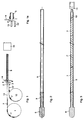
- FIG. 1 shows a schematic view of a device for filling a hose
- FIG. 1a shows a detailed view
- FIGS. 2 and 3 production steps in the manufacture of a radiator holder according to the invention.
- FIG. 1 schematically shows a vibrating device for radioactive seeds with 1 and with 12 a vibrating device for non-radioactive filler parts, from each of which two devices 1 and 12 a transport hose 13 or 13 'comes off, which with seeds 7 or filler parts 7' be loaded.
- the end of each transport tube 13, 13 ' can be coupled to a guide sleeve 4 which guides a plastic tube or shrink tube 5, as shown in FIG. 1a.
- the sleeve 4 is adjustable on a carrier 14, which is actuated by a drive device, between positions in which its bore is aligned with the transport hoses 13 and 13 '.
- the shrink tube 5 is inserted into the sleeve 4 and is easily detachable.
- a tip 6 can already be attached or inserted into this plastic tube 5 at the end facing away from the support 4, as is shown on a larger scale in FIG.
- the shrink tube 5 is filled by shaking the seeds 7 into the tube or by pushing in with the aid of a wire tappet or the like. If the tube 5 is filled sufficiently, the supply of the seeds or filling elements is stopped. The filling check or the stopping can be carried out with the aid of a light barrier 8 which actuates locking devices 2 in the transport hoses 13, 13 'so that the seeds 7 or filling parts 7' can no longer enter the hose 5 or in the transport hose 13, 13 'are stopped. In this way, an automatic filling of the hose 5 can be provided under computer control.
- the shrink tube 5 It is possible to cut the shrink tube 5 to length before it is filled or only after the seeds 7 and filling pieces 7 'have been introduced.
- the transparency of the hose is useful with regard to the light barrier 8 and to determine the content of the lamp holder.
- Usual diameters of the seed are 0.3 to 0.5 mm, in particular 0.3 to 0.4 mm, and it is preferred to use shrink tubes which have an inside diameter of 0.6 mm and a size of 0.3 mm are shrinkable.
- an end part 9 of a tip 6 can be inserted into the end of a shrink tube, wherein - as FIG. 3 shows - the shrink tube 5 can be shrunk onto this end part 9 of the tip 6.
- a coupling device 11 with a guide part 10 is inserted, onto which guide part 10 the end of the shrink tube is shrunk, so that, as shown in FIG. 3, there is a flexible radiator holder provided with a tip 6 and a coupling part 11.
- a wire core is inserted into the shrink tubing, which is usually in an irregular shape, e.g. a steel wire onto which the hose is shrunk in order to achieve its required roundness.
- This shrinking takes place in particular over a diameter of 5 mm.
- pre-shrunk tube 5 provided with the wire core is inserted into the guide sleeve 4 and the inner wire is removed.
- the shrink tube is by means of the device 1 used for loosening the seeds 7 or the spacers 7 'and the device 12, which are used by vibrators, vibrators or the like. are formed, filled, the seeds 7 and the filling parts 7 ′′ being introduced into the transport tube in the selected order.
- the shrinking of the coupling part 11 takes place, which can be coupled to the tip of a guide or insertion wire, with which the lamp holder is inserted into the radiation needle and, if necessary, removed therefrom.
- the filled and provided with the tip 6 and coupling part 11 hose 5 is then in a heater 14, e.g. in a hot air stream, in which the final shrinking takes place at about 100 ° C.
- the transparency of the shrink tube enables the seeds 7 or filler parts 7 'to be recognized.
- An attached code on the seed e.g. Color code, bar code or the like serves to identify them; also the application of a magnetic (bar) code, e.g. on NiFeCo metals is possible. This code, which can be read by the radiation device, ensures that the arrangement in the clinic is unmistakable.
- the shape of the tip 6 and the coupling part 11 can be chosen as desired; the diameter of the seeds can also be selected; The inside diameter of the plastic tube is adapted to the diameter of the seeds, whereby its shrinking behavior must be taken into account.
- the tubes can be filled with radioactive seeds and filler parts made of different metals or materials.
- the activity of the seeds is measured in particular immediately before being introduced into the shrink tube and only seeds with predetermined activity values (eg ⁇ 3% of the specified value) are inserted into the shrink tube. This allows the activity distribution in the shrink tube to be given a certain, possibly constant, course.
Landscapes
- Health & Medical Sciences (AREA)
- Engineering & Computer Science (AREA)
- Biomedical Technology (AREA)
- Pathology (AREA)
- Nuclear Medicine, Radiotherapy & Molecular Imaging (AREA)
- Radiology & Medical Imaging (AREA)
- Life Sciences & Earth Sciences (AREA)
- Animal Behavior & Ethology (AREA)
- General Health & Medical Sciences (AREA)
- Public Health (AREA)
- Veterinary Medicine (AREA)
- Radiation-Therapy Devices (AREA)
- Pretreatment Of Seeds And Plants (AREA)
- Supports For Pipes And Cables (AREA)
- Fastening Of Light Sources Or Lamp Holders (AREA)
Description
- Die Erfindung betrifft einen Strahlerhalter zum Einsatz in interstitiell eingebrachte Bestrahlungsnadeln, umfassend eine Kunststoffhülle und zumindest ein in dieser angeordnetes, vorzugsweise langgestrecktes, radioaktives Seed. Ferner betrifft die Erfindung ein Verfahren zur Herstellung radioaktiver Strahlerhalter zum Einsatz in interstitiell eingebrachte Bestrahlungsnadeln und eine Einrichtung zur Herstellung derartiger Strahlerhalter zum Einsatz in interstitiell eingebrachte Bestrahlungsnadeln.
- Bekannt ist es, daß ein Strahlerhalter mittels einer Pinzette von Hand aus oder mit einer Handhabungsvorrichtung gemäß der AT-PS 385 195 in Hohlnadeln zur interstitiellen Bestrahlung eingebracht wird. Dabei ergibt sich ein erhöhter Aufwand zur Fixierung des aus einem radioaktiven Drahtstück bestehenden Seeds und der Spitze des Strahlerhalters. Aufgrund der bei der Manipulation entstehenden hohen Strahlenbelastung bringt diese Anwendung Strahlenschutzprobleme mit sich. Ferner ist es bekannt, aktive Strahlenquellen in Kunststoffumhüllungen lose einzuführen, mit der Gefahr, daß die Strahlenquellen ihre Position verändern können bzw. im Falle eines Bruches der Umhüllung die Strahlenquellen austreten können.
- Aus der DE-A1-1,065.989 ist weiters ein Strahlerhalter zum Einsatz in interstitiell eingebrachte Bestrahlungsnadeln, umfassend eine Kunststoffhülle und zumindest ein in diese angeordnetes radioaktives Seed bekannt, wobei die Strahlungsquelle(n) in einer zylindrischen Hülse aus Gummi oder Kunststoff eingelegt ist. Beispielsweise ist die Strahlungsquelle mit einer Mehrzahl von, durch kurze Abstände getrennten, Drahtstückchen aus radioaktivem Material gebildet. Die Lagehaltung der Seeds erfolgt dort durch reversible, lokale Radial-Dehnung der elastischen Hülse an den Stellen, wo sich die Seeds befinden. Die Abschnitte zwischen den Strahlerelementen weisen weiterhin Elastizität auf, somit aber die Lage-Haltung der Seeds relativ unsicher bleibt und bei Einwirkung relativ geringer Kräfte, z.B. bei Manipulation oder beim Einführen, unerwünschte Relativverschiebungen der Seeds erfolgen können.
- Ergänzend sei zum Stand der Technik noch auf die DE-A1-1,095.963 verwiesen, welche eine Einrichtung zur Beschickung eines Applikators mit radioaktiven Strahlerelementen zum Gegenstand hat, sowie auf die Literaturstelle J.L.Haybittle et al. "A simple after-loading technique for the treatment of cancer of the cervix" in British J.Radiology, April 1975, pp.295-298, aus welcher die Anordnung von länglichen radioaktiven Seeds in röhrenartige PVC-Nadeln ohne eigene Hülle hervorgeht.
- Ziel der Erfindung ist es, diese vorbeschriebenen Nachteile zu beheben und bei hoher Biegsamkeit des Strahlerhalters zur Optimierung der Tumorbestrahlungs-Geometrie eine gegen äußere Einwirkung unempfindliche echte Lagefixierung der Seeds zu erreichen. Weiteres Ziel der Erfindung ist es, eine hohe Flexibilität bei der Einführung von Low-Dose-radioaktiven Elementen bzw. Seeds in den menschlichen Körper bzw. in Bestrahlungsnadeln zu erreichen, bei gleichzeitig genauer Dosierbarkeit und Positionierbarkeit.
- Erfindungsgemäß ist ein Strahlerhalter der eingangs genannten Art dadurch gekennzeichnet, daß die Kunststoffhülle von einer bzw. einem auf das zumindest eine Seed unter dessen Lagefixierung thermisch aufgeschrumpften Kunststoffumhüllung bzw. Kunststoffschrumpfschlauch gebildet ist. Durch das Einbringen kurzer Drahtstücke in den Kunststoffschrumpfschlauch und nachträgliches Aufschrumpfen wird die Beweglichkeit des Seeds in der Bestrahlungsnadel verbessert. Gleichzeitig kann der Schrumpfschlauch des Strahlerhalters zur Fixierung der Spitze und/oder einem Kupplungsteil zum Ankuppeln an eine Handhabungsvorrichtung, z.B. einen Drahtschieber, dienen. Der Einsatz eines Schrumpfschlauches ermöglicht eine sichere Befestigung des vorderen und hinteren Endabschlusses des Strahlerhalters, da die auf die Endteile aufgeschrumpften Kunststoff-Schrumpfschläuche ausgesprochen fest mit diesen verbunden werden können. Ferner wird eine Fixierung der Seeds in der Umhüllung erreicht, welche Tatsache ausgesprochen wichtig für die Dosisberechnung ist. Bedingt durch die erfindungsgemäße Messung der Aktivität der einzelnen Seeds nach der Neutronenaktivierung im Reaktor und der Sortierung, vorzugsweise gemäß ± 3% Aktivitätsschwankung ergeben sich qualitativ weitaus höherstehendere Strahlerhalter, als es bei den bisherigen Ausführungsformen erreichbar war; dies zeigte sich auch in praktischen Versuchen, in denen die Lage und die Aktivität der Seeds und damit die an den menschlichen Körper abgegebene Dosis weitaus besser bestimmbar war als bisher. Der erfindungsgemäße Strahlerhalter vereinbart somit den Vorteil eines leicht befüllbaren Schlauches mit einer Lagefixierung der eingefüllten Seeds; als weiterer Vorteil ergibt es sich, daß im Falle eines Bruches einer Umhüllung die im Kunststoffschrumpfschlauch befindlichen Seeds lagefest gehalten werden und durch die Bruchstelle nicht austreten können. Für die Qualität der Therapie und für die Sicherheit des Hantierenden bzw. Behandelten werden somit wesentliche Vorteile erreicht.
- Der Strahlerhalter kann eine Anzahl von hintereinander in den Schrumpfschlauch eingeschrumpften gegebenenfalls bezüglich des radioaktiven Materials unterschiedliche Seeds umfassen. Auf diese Weise können Strahlerhalter vorgegebener Dosis erstellt werden, die entsprechend den verschiedenen Anwendungszwecken in die Bestrahlungsnadeln eingebracht werden können; die Reihenfolge und Lage der Seeds in der Bestrahlungsnadel wird beim Befüllen vorgegeben und bleibt danach unverändert. Zur genaueren Einregelung der Strahlungsdosis der von dem Strahlerhalter abgegebenen Strahlung kann vorgesehen sein, daß der Schrumpfschlauch in vorgegebener Aufeinanderfolge radioaktive Seeds und nicht radioaktive Füllteile bzw. Distanzstücke umfaßt. Die Seeds und die Füllteile können abwechselnd oder in bestimmter Aufeinanderfolge in den Schrumpfschlauch eingeschrumpft werden, sodaß eine Strahlenquelle mit über ihrer Länge definierter Strahlung erstellt wird.
- Vorteilhafterweise wird ein transparenter Schrumpfschlauch eingesetzt, der eine Schrumpftemperatur von etwa 100°C und einen Schrumpfgrad in radialer Richtung von etwa 50 % besitzt. Die Transparenz des Schrumpfschlauches ist für die optische Feststellung seines Inhalts maßgeblich; ferner kann die Befüllung des Schrumpfschlauches mittels optischer Detektoren bzw. Lichtschranken bzw. eines Diodenmeßsystems überwacht werden. Eine Schrumpfungstemperatur von etwa 100°C ist zweckmäßig, um nicht aufwendige Schrumpfungseinrichtungen zur Verfügung stellen zu müssen; der gewählte Schrumpfungsgrad in radialer Richtung ergibt einen gut biegbaren langgestreckten Körper des Strahlerhalters, der in gerade oder gekrümmte Bestrahlungsnadeln bzw. -schläuchen gut ein- und ausfahrbar ist.
- Ein Verfahren der eingangs genannten Art ist erfindungsgemäß dadurch gekennzeichnet, daß zumindest ein radioaktives Seed bzw. eine Anzahl von radioaktiven Seeds in einen, vorzugsweise transparenten und gegebenenfalls bereits abgelängten Schrumpfschlauch eingeführt werden, und daß daraufhin der Schlauch geschrumpft wird. Vorteilhaft ist es dabei, wenn zusätzlich zu den Seeds eine Anzahl von nicht radioaktiven Füllteilen bzw. Distanzstücken in vorgegebener Aufeinanderfolge mit den Seeds in den Schrumpfschlauch eingebracht wird.
- Bei einer bevorzugten Ausführungsform der Erfindung ist vorgesehen, daß vor dem Einbringen der Seeds bzw. der Füllteile eine Seele, z.B. ein Stahldraht, in den Schrumpfschlauch eingeführt wird, deren Durchmesser größer als der Durchmesser der Seeds und Füllstücke ist, und daß der Schrumpfschlauch auf den Durchmesser der Seele vorgeschrumpft wird. Bei dieser Vorgangsweise liegt zum Befüllen ein Schrumpfschlauch definierten und ziemlich genau runden Durchmessers vor, der leicht befüllt werden kann.
- Eine Einrichtung der eingangs genannten Art ist erfindungsgemäß dadurch gekennzeichnet, daß eine Führungshülse vorgesehen ist, an bzw. in die ein Schrumpfschlauch ansetzbar bzw. einsteckbar ist, und daß die Führungshülse zur Einführung der Seeds in den Schrumpfschlauch an das Ende einer von einer Rütteleinrichtung für radioaktive Seeds kommenden, vorzugsweise durchsichtigen Transportleitung anlegbar bzw. ankoppelbar ist und daß der Einrichtung eine Heizeinrichtung, z.B. ein Heißlufterzeuger, zum Schrumpfen des Schrumpfschlauches nachgeordnet ist, durch die der gefüllte Schlauch mit einer Transporteinrichtung durchbewegbar ist.
- Eine bevorzugte Ausführungsform der erfindungsgemäßen Einrichtung sieht vor, daß die Führungsteile mittels einer Umschalteinrichtung bzw. einer Weiche in willkürlicher Weise an die Transportleitung der Rütteleinrichtungen für die Seeds und eine Transportleitung einer Rütteleinrichtung für nichtaktive Füllteile bzw. Distanzstücke anschließbar ist.
- Im folgenden wird die Erfindung beispielsweise anhand der Zeichnung näher erläutert. Es zeigen Fig.1 eine schematische Ansicht einer Vorrichtung zum Befüllen eines Schlauches, Fig.1a eine Detailansicht und Fig.2 und 3 Herstellungsschritte bei der Herstellung eines erfindungsgemäßen Strahlerhalters.
- In Fig.1 ist mit 1 schematisch eine Rüttelvorrichtung für radioaktive Seeds und mit 12 eine Rüttelvorrichtung für nicht radioaktive Füllteile dargestellt, von welchen beiden Einrichtungen 1 und 12 jeweils ein Transportschlauch 13 bzw. 13' abgeht, die mit Seeds 7 bzw. Füllteilen 7' beschickt werden. Das Ende jedes Transportschlauches 13,13' ist mit einer Führungshülse 4 koppelbar, die einen Kunststoffschlauch bzw. Schrumpfschlauch 5 führt, wie Fig.1a zeigt. Die Hülse 4 ist auf einem Träger 14, der von einer Antriebseinrichtung betätigt ist, zwischen Stellungen verstellbar, in denen ihre Bohrung mit den Transportschläuchen 13 bzw. 13' fluchtet. Der Schrumpfschlauch 5 ist in die Hülse 4 eingesteckt und leicht lösbar. In diesen Kunststoffschlauch 5 kann bereits eine Spitze 6 an dem der Stütze 4 abgewandten Ende angebracht bzw. eingesetzt sein, so wie dies in Fig.2, in größerem Maßstab dargestellt ist.
- Das Befüllen des Schrumpfschlauches 5 erfolgt durch Einrütteln der Seeds 7 in den Schlauch oder durch Einschieben mit Hilfe eines Drahtstößels od.dgl. Wenn der Schlauch 5 ausreichend gefüllt ist, wird die Zufuhr der Seeds bzw. Füllelemente gestoppt. Die Füllkontrolle bzw. das Stoppen kann mit Hilfe einer Lichtschranke 8 erfolgen, die in den Transportschläuchen 13,13' Sperrvorrichtungen 2 betätigt, sodaß die Seeds 7 bzw. Füllteile 7' nicht mehr in den Schlauch 5 eintreten können bzw. im Transportschlauch 13,13' angehalten werden. Auf diese Weise kann ein automatisches Befüllen des Schlauches 5 unter Rechnersteuerung vorgesehen werden.
- Es ist möglich, den Schrumpfschlauch 5 bereits vor seiner Befüllung abzulängen oder auch erst nachdem die Seeds 7 und Füllstücke 7' eingebracht worden sind. Die Transparenz des Schlauches ist zweckmäßig im Hinblick auf die Lichtschranke 8 und zur Feststellung des Inhaltes des Strahlerhalters. Übliche Durchmesser des Seeds liegen bei 0,3 bis 0,5 mm, insbesondere bei 0,3 bis 0,4 mm, und es werden bevorzugt Schrumpfschläuche eingesetzt, die einen Innendurchmesser von 0,6 mm besitzen und auf die Größe von 0,3 mm schrumpfbar sind.
- Wie in Fig.2 dargestellt, kann in das Ende eines Schrumpfschlauches ein Endteil 9 einer Spitze 6 eingesetzt werden, wobei - wie Fig.3 zeigt - der Schrumpfschlauch 5 auf diesen Endteil 9 der Spitze 6 aufgeschrumpft werden kann. In gleicher Weise kann in das andere Ende des Schrumpfschlauches 5 eine Kupplungseinrichtung 11 mit einem Führungsteil 10 eingesetzt werden, auf welchen Führungsteil 10 das Ende des Schrumpfschlauches aufgeschrumpft wird, sodaß sich, wie in Fig.3 gezeigt, ein biegsamer, mit einer Spitze 6 und einem Kupplungsteil 11 versehener Strahlerhalter ergibt.
- Vorteilhafterweise wird in die üblicherweise in unregelmäßiger Form vorliegenden Schrumpfschläuche vor dem Befüllen eine Drahtseele eingeführt, z.B. ein Stahldraht, auf den der Schlauch vorgeschrumpft wird, um seine notwendige Rundheit zu erzielen. Dieses Vorschrumpfen erfolgt insbesondere auf einem Durchmesser von 5 mm.
- Daraufhin wird der mit der Drahtseele versehene vorgeschrumpfte Schlauch 5 in die Führungshülse 4 eingeführt und der Innendraht entfernt.
- Darauffolgend wird der Schrumpfschlauch mittels der zur Auflockerung der Seeds 7 bzw. der Distanzstücke 7' dienenden Vorrichtung 1 und der Vorrichtung 12, die von Rüttlern, Vibratoren od.dgl. gebildet sind, gefüllt, wobei die Seeds 7 und die Füllteile 7'' in gewählter Reihenfolge in den Transportschlauch eingebracht werden.
- Schließlich erfolgt das Aufschrumpfen des Kupplungsteiles 11, der mit der Spitze eines Führungs- bzw. Einführdrahtes kuppelbar ist, mit dem der Strahlerhalter in die Bestrahlungsnadel eingeführt und allenfalls daraus wieder entfernt wird.
- Der befüllte und mit der Spitze 6 und Kupplungsteil 11 versehene Schlauch 5 wird daraufhin in ein Heizgerät 14, z.B. in einen Heißluftstrom, eingebracht, in dem bei etwa 100°C das Endschrumpfen stattfindet.
- Die Transparenz des Schrumpfschlauches ermöglicht ein Erkennen der Seeds 7 bzw. Füllteile 7'. Ein angebrachter Code am Seed, z.B. Farbcode, Barcode od.dgl., dient zu deren Identifizierung; auch die Anbringung eines magnetischen (Bar)codes, z.B. an NiFeCo-Metallen ist möglich. Dieser vom Bestrahlungsgerät lesbare Code sichert die verwechslungsfreie Anordnung in der Klinik.
- Die Form der Spitze 6 und des Kupplungsteiles 11 kann beliebig gewählt werden; ebenso ist der Durchmesser der Seeds wählbar; an den Durchmesser der Seeds wird der Innendurchmesser des Kunststoffschlauches angepaßt, wobei dessen Schrumpfverhalten zu beachten ist.
- Die Schläuche können mit radioaktiven Seeds und Füllteilen aus verschiedenen Metallen bzw. Materialien gefüllt werden.
- Zweckmäßig kann es sein, wenn die Aktivität der Seeds insbesondere unmittelbar vor dem Einbringen in den Schrumpfschlauch gemessen wird und nur Seeds mit vorbestimmten Aktivitätswerten (z.B. ± 3% vom vorgegebenen (Wert) in den Schrumpfschlauch eingeführt werden. Damit kann der Aktivitätsverteilung im Schrumpfschlauch ein bestimmter, gegebenenfalls konstanter, Verlauf verliehen werden.
Claims (18)
- Strahlerhalter zum Einsatz in interstitiell eingebrachte Bestrahlungsnadeln, umfassend eine Kunststoffhülle (5) und zumindest ein in dieser angeordnetes, vorzugsweise langgestrecktes, radioaktives Seed (7) , dadurch gekennzeichnet, daß die Kunststoffhülle von einer bzw. einem auf das zumindest eine Seed (7) unter dessen Lagefixierung thermisch aufgeschrumpften Kunststoffumhüllung bzw. Kunststoffschrumpfschlauch (5) gebildet ist.
- Strahlerhalter nach Anspruch 1, dadurch gekennzeichnet, daß in dem Schrumpfschlauch (5) hintereinander eine Anzahl von eingeschrumpften Seeds (7) angeordnet sind.
- Strahlerhalter nach Anspruch 1 oder 2, dadurch gekennzeichnet, daß in dem Schrumpfschlauch (5) in vorgegebener Aufeinanderfolge radioaktive Seeds (7) und nicht radioaktive, vorzugsweise gleichen Durchmesser wie die Seeds (7) aufweisende Füllteile bzw. Distanzstücke (7') angeordnet sind.
- Strahlerhalter nach einem der Ansprüche 1 bis 3, dadurch gekennzeichnet, daß der vorzugsweise transparente Schrumpfschlauch (5) eine Schrumpftemperatur von etwa 100°C und einen Schrumpfgrad in radialer Richtung von etwa 50 % besitzt.
- Strahlerhalter nach einem der Ansprüche 1 bis 4, dadurch gekennzeichnet, daß der Schrumpfschlauch (5) mit einer Spitze (6) versehen ist.
- Strahlerhalter nach Anspruch 5, dadurch gekennzeichnet, daß die Spitze (6) mit dem Schrumpfschlauch (5) verklebt ist oder daß ein hinterer Endteil (9) der Spitze (6) in den Schrumpfschlauch (5) ragt und der Schrumpfschlauch (5) auf diesen Endteil (9) aufgeschrumpft ist.
- Strahlerhalter nach einem der Ansprüche 1 bis 6, dadurch gekennzeichnet, daß der Schrumpfschlauch (5) an einem Endteil mit einem Kupplungsteil (11) angeschlossen ist, der an dem Schrumpfschlauch (5) angeklebt ist oder mit einem Fortsatz (10) in den Schrumpfschlauch (5) ragt, wobei der Schlauch (5) auf den Fortsatz (10) aufgeschrumpft ist.
- Strahlerhalter nach einem der Ansprüche 1 bis 7, dadurch gekennzeichnet, daß die Seeds (7) und die Füllteile (7') hintereinander ohne Abstand im Schrumpfschlauch (5) angeordnet sind.
- Strahlerhalter nach einem der Ansprüche 1 bis 8, dadurch gekennzeichnet, daß die radiale Schrumpfbarkeit des Schrumpfschlauches (5) größer ist als seine Schrumpfbarkeit in Längsrichtung.
- Strahlerhalter nach einem der Ansprüche 1 bis 9, dadurch gekennzeichnet, daß die Seeds (7) und/oder die Distanzstücke (7') mit Kennungen Markierungen, z.B. Farbmarkierungen, magnetischen Markierungen, vorzugsweise im Barcode, gekennzeichnet sind.
- Verfahren zur Herstellung radioaktiver Strahlerhalter zum Einsatz in interstitiell eingebrachte Bestrahlungsnadeln nach einem der Ansprüche 1 bis 10, dadurch gekennzeichnet, daß zumindest ein radioaktives Seed (7), vorzugsweise eine Anzahl von radioaktiven Seeds (Strahlerelementen), in einen, vorzugsweise transparenten und gegebenenfalls bereits abgelängten Schrumpfschlauch (5) eingeführt werden und daß daraufhin der Schlauch auf das (die) Seed(s) unter dessen Lagefixierung thermisch aufgeschrumpft wird.
- Verfahren nach Anspruch 11, dadurch gekennzeichnet, daß zusätzlich zu den Seeds (7) eine Anzahl von nicht radioaktiven Füllteilen bzw. Distanzstücken (7') in vorgegebener Aufeinanderfolge mit den Seeds in den Schrumpfschlauch eingebracht wird.
- Verfahren nach Anspruch 11 oder 12, dadurch gekennzeichnet, daß vorzugsweise vor dem Einführen der Seeds -eine Spitze (6) und vorzugsweise nach dem Einführen der Seeds ein Kupplungsteil (11), insbesondere inclusive Codierung, mit dem abgelängten Schlauch (5), z.B. durch Kleben, verbunden oder in den abgelängten Schlauch eingesteckt und beim Schrumpfvorgang am Schlauch befestigt werden.
- Verfahren nach einem der Ansprüche 11 bis 13, dadurch gekennzeichnet, daß vor dem Einbringen der Seeds (7) bzw. der Füllteile bzw. Distanzstücke (7') eine Seele, z.B. ein Stahldraht, in den Schrumpfschlauch (5) eingeführt wird, deren Durchmesser größer als der Durchmesser der Seeds und Füllteile bzw. Distanzstücke ist, und daß der Schrumpfschlauch auf den Durchmesser der Seele vorgeschrumpft wird.
- Verfahren nach einem der Ansprüche 11 bis 14, dadurch gekennzeichnet, daß die Aktivität der Seeds (7) insbesondere unmittelbar vor dem Einbringen in den Schrumpfschlauch (5) gemessen wird und nur Seeds mit vorbestimmten Aktivitätswerten (z.B. im Bereich von ± 3% bezogen auf den gewünschten Wert) in den Schrumpfschlauch eingeführt werden.
- Einrichtung zum Herstellen von Strahlerhaltern nach einem der Ansprüche 1 bis 10 zum Einsatz in interstitiell eingebrachte Bestrahlungsnadeln bzw. zur Durchführung des Verfahrens nach einem der Ansprüche 11 bis 15, dadurch gekennzeichnet, daß eine Führungshülse (4) vorgesehen ist, an bzw. in die ein Schrumpfschlauch (5) ansetzbar bzw. einsteckbar ist, und daß die Führungshülse (4) zur Einführung der Seeds (7) in den Schrumpfschlauch (5) an das Ende einer von einer Rütteleinrichtung (1) für radioaktive Seeds (7) kommenden, vorzugsweise durchsichtigen Transportleitung (13) anlegbar bzw. ankoppelbar ist und daß der Einrichtung eine Heizeinrichtung, z.B. ein Heißlufterzeuger, zum Schrumpfen des Schrumpfschlauches nachgeordnet ist, durch die der gefüllte Schlauch (5) mit einer Transporteinrichtung durchbewegbar ist.
- Einrichtung nach Anspruch 16, dadurch gekennzeichnet, daß die Führungsteile (4) mittels einer Umschalteinrichtung bzw. einer Weiche (14) in willkürlicher Weise an die Transportleitung (13) der Rütteleinrichtungen (1) für die Seeds (7) und eine Transporteinrichtung (13') einer Rütteleinrichtung (12) für nichtaktive Füllteile bzw. Distanzstücke (7') anschließbar ist.
- Einrichtung nach Anspruch 16 oder 17, dadurch gekennzeichnet, daß in der Transportleitung (13) bzw. der Transportleitung (13') knapp vor der Führungshülse (4) eine von einer die Transportleitungen (13,13') überwachenden Lichtschranke (8) betätigbare Sperrvorrichtung (2) vorgesehen ist.
Applications Claiming Priority (2)
| Application Number | Priority Date | Filing Date | Title |
|---|---|---|---|
| AT1471/90 | 1990-07-11 | ||
| AT0147190A AT397468B (de) | 1990-07-11 | 1990-07-11 | Strahlerhalter sowie verfahren und vorrichtung zur herstellung desselben |
Publications (2)
| Publication Number | Publication Date |
|---|---|
| EP0466681A1 EP0466681A1 (de) | 1992-01-15 |
| EP0466681B1 true EP0466681B1 (de) | 1995-11-08 |
Family
ID=3514629
Family Applications (1)
| Application Number | Title | Priority Date | Filing Date |
|---|---|---|---|
| EP91890142A Expired - Lifetime EP0466681B1 (de) | 1990-07-11 | 1991-07-05 | Strahlerhalter sowie Verfahren und Einrichtung zur Herstellung desselben |
Country Status (4)
| Country | Link |
|---|---|
| EP (1) | EP0466681B1 (de) |
| AT (2) | AT397468B (de) |
| DE (1) | DE59106840D1 (de) |
| PT (1) | PT98283A (de) |
Cited By (20)
| Publication number | Priority date | Publication date | Assignee | Title |
|---|---|---|---|---|
| US6582352B2 (en) | 1994-06-10 | 2003-06-24 | Schneider (Europe) A.G. | Medical appliance for treatment by ionizing radiation |
| US6599230B2 (en) | 1996-02-29 | 2003-07-29 | Scimed Life Systems, Inc. | Intravascular radiation delivery system |
| US6616629B1 (en) | 1994-06-24 | 2003-09-09 | Schneider (Europe) A.G. | Medical appliance with centering balloon |
| US6905455B2 (en) | 2000-11-01 | 2005-06-14 | Medi-Physics, Inc. | Radioactive member and method of making |
| US7008368B2 (en) | 2001-11-02 | 2006-03-07 | Ideamatrix, Inc. | Method for making treatment strands |
| US7094198B2 (en) | 2001-11-02 | 2006-08-22 | Worldwide Medical Technologies, Llc | Delivery system and method for interstitial radiation therapy using seed elements with ends having one of projections and indentations |
| US7211039B2 (en) | 2001-11-02 | 2007-05-01 | Worldwide Medical Technologies Llc | Strand with end plug |
| US7244226B2 (en) | 2001-11-02 | 2007-07-17 | Worldwide MedicalTechnologies, LLC | Methods for making therapeutic elements for implantation into patient tissue |
| US7736293B2 (en) | 2005-07-22 | 2010-06-15 | Biocompatibles Uk Limited | Implants for use in brachytherapy and other radiation therapy that resist migration and rotation |
| US7736294B2 (en) | 2003-05-13 | 2010-06-15 | Biocompatibles Uk Limited | Delivery system and method for interstitial radiation therapy using seed strands with custom end spacing |
| US7874976B1 (en) | 2006-09-07 | 2011-01-25 | Biocompatibles Uk Limited | Echogenic strands and spacers therein |
| US7878964B1 (en) | 2006-09-07 | 2011-02-01 | Biocompatibles Uk Limited | Echogenic spacers and strands |
| US7942843B2 (en) | 2008-08-18 | 2011-05-17 | Navotek Medical Ltd. | Implantation device for soft tissue markers and other implants |
| US7985172B2 (en) | 2006-05-09 | 2011-07-26 | Biocompatibles Uk Limited | After-loader devices and kits |
| US8066627B2 (en) | 2001-11-02 | 2011-11-29 | Biocompatibles Uk Limited | Delivery system and method for interstitial radiation therapy using strands constructed with extruded strand housings |
| US8164064B2 (en) | 2004-08-12 | 2012-04-24 | Navotek Medical Ltd. | Localization of a radioactive source within a body of a subject |
| US8187159B2 (en) | 2005-07-22 | 2012-05-29 | Biocompatibles, UK | Therapeutic member including a rail used in brachytherapy and other radiation therapy |
| US8198600B2 (en) | 2004-08-12 | 2012-06-12 | Navotek Medical Ltd. | Localization of a radioactive source |
| US8239002B2 (en) | 2004-08-12 | 2012-08-07 | Novatek Medical Ltd. | Guiding a tool for medical treatment by detecting a source of radioactivity |
| US8470294B2 (en) | 2000-11-16 | 2013-06-25 | Microspherix Llc | Flexible and/or elastic brachytherapy seed or strand |
Families Citing this family (14)
| Publication number | Priority date | Publication date | Assignee | Title |
|---|---|---|---|---|
| DE69516679T2 (de) * | 1995-06-22 | 2000-11-23 | Schneider (Europe) Gmbh, Buelach | Arzneigerät für die Behandlung eines Teiles eines Körpergefässes mittels Ionisierungsbestrahlung |
| WO1997022379A2 (en) | 1995-12-18 | 1997-06-26 | Kerisma Medical Products, L.L.C. | Fiberoptic-guided interstitial seed manual applicator and seed cartridge |
| WO1997046276A1 (en) * | 1996-06-06 | 1997-12-11 | W.L. Gore & Associates, Inc. | Implantable circumferential treatment delivery device |
| NL1003528C2 (nl) | 1996-07-05 | 1998-01-07 | Optische Ind Oede Oude Delftoe | Samenstel van een capsule voor brachytherapie en een leidraad. |
| US6730013B1 (en) | 1999-04-09 | 2004-05-04 | Medi-Physics, Inc. | Method and apparatus for loading delivery systems for brachytherapy seeds |
| AU7497200A (en) * | 1999-04-09 | 2000-11-14 | Medi-Physics, Inc. | Method and apparatus for loading delivery systems for brachytherapy seeds |
| WO2000064538A1 (en) * | 1999-04-28 | 2000-11-02 | Medi Physics, Inc. | Products and methods for brachytherapy |
| US6264600B1 (en) * | 1999-10-21 | 2001-07-24 | Peter D. Grimm | Hollow suture member with radioactive seeds positioned therein for treatment of prostate cancer |
| DE10204818C2 (de) * | 2002-02-06 | 2003-11-27 | Eurotope Entwicklungsgesellsch | Gerät und Verfahren zur Beladung von Implantationshohlnadeln mit Strahlungsquellen aus Strahlungsquellenketten zur interstitiellen Brachytherapie von Gewebe |
| EP1407799B1 (de) * | 2002-10-07 | 2006-01-04 | Nucletron B.V. | Vorrichtung zur Implantation einer Reihe von radioaktiven Samen und nicht-radioaktiven Distanzhaltern |
| DE50307128D1 (de) * | 2003-06-03 | 2007-06-06 | Eckert & Ziegler Eurotope Gmbh | Gerät und Verfahren zur Beladung von Implantationshohlnadeln mit Strahlungsquellen aus Strahlungsquellenketten zur interstitiellen Brachytherapie von Gewebe |
| US7351192B2 (en) * | 2004-05-25 | 2008-04-01 | Core Oncology, Inc. | Selectively loadable/sealable bioresorbable carrier assembly for radioisotope seeds |
| EP1922011B1 (de) * | 2005-08-11 | 2012-05-02 | Navotek Medical Ltd. | Lokalisation einer radioaktiven quelle |
| WO2007053823A2 (en) * | 2005-10-31 | 2007-05-10 | Biolucent, Inc. | Brachytherapy apparatus and methods of using same |
Family Cites Families (5)
| Publication number | Priority date | Publication date | Assignee | Title |
|---|---|---|---|---|
| DE1065989B (de) * | 1955-04-01 | 1959-09-24 | Willy Rüsch K. G., Rommelshausen über Waiblingen | Geraet zur radioaktiven bestrahlung von koeperinnenraumen |
| DE1095963B (de) * | 1959-07-15 | 1960-12-29 | Felix Wachsmann Dr Ing | Anordnung fuer die Durchfuehrung von oberflaechlichen oder intrakavitaeren Behandlungen mit Radium oder kuenstlich radioaktiven Strahlern |
| US3964468A (en) * | 1975-05-30 | 1976-06-22 | The Board Of Trustees Of Leland Stanford Junior University | Bioptome |
| US4697575A (en) * | 1984-11-21 | 1987-10-06 | Henry Ford Hospital | Delivery system for interstitial radiation therapy including substantially non-deflecting elongated member |
| DE3442762A1 (de) * | 1984-11-23 | 1986-06-26 | Anwer Dipl.-Ing. 8520 Erlangen Puthawala | Ferngesteuerte afterloading vorrichtung zur brachycurie-therapie von tumoren |
-
1990
- 1990-07-11 AT AT0147190A patent/AT397468B/de not_active IP Right Cessation
-
1991
- 1991-07-05 AT AT91890142T patent/ATE129911T1/de not_active IP Right Cessation
- 1991-07-05 DE DE59106840T patent/DE59106840D1/de not_active Expired - Fee Related
- 1991-07-05 EP EP91890142A patent/EP0466681B1/de not_active Expired - Lifetime
- 1991-07-10 PT PT98283A patent/PT98283A/pt not_active Application Discontinuation
Cited By (36)
| Publication number | Priority date | Publication date | Assignee | Title |
|---|---|---|---|---|
| US6582352B2 (en) | 1994-06-10 | 2003-06-24 | Schneider (Europe) A.G. | Medical appliance for treatment by ionizing radiation |
| US6616629B1 (en) | 1994-06-24 | 2003-09-09 | Schneider (Europe) A.G. | Medical appliance with centering balloon |
| US6599230B2 (en) | 1996-02-29 | 2003-07-29 | Scimed Life Systems, Inc. | Intravascular radiation delivery system |
| US7547274B2 (en) | 2000-11-01 | 2009-06-16 | Medi-Physics, Inc. | Radioactive member and method of making |
| US6905455B2 (en) | 2000-11-01 | 2005-06-14 | Medi-Physics, Inc. | Radioactive member and method of making |
| US8033981B2 (en) | 2000-11-01 | 2011-10-11 | Medi-Physics, Inc. | Radioactive member and method of making |
| US8470294B2 (en) | 2000-11-16 | 2013-06-25 | Microspherix Llc | Flexible and/or elastic brachytherapy seed or strand |
| US8821835B2 (en) | 2000-11-16 | 2014-09-02 | Microspherix Llc | Flexible and/or elastic brachytherapy seed or strand |
| US7094198B2 (en) | 2001-11-02 | 2006-08-22 | Worldwide Medical Technologies, Llc | Delivery system and method for interstitial radiation therapy using seed elements with ends having one of projections and indentations |
| US7942803B2 (en) | 2001-11-02 | 2011-05-17 | Biocompatibles Uk Limited | Delivery system and method for interstitial radiation therapy |
| US7211039B2 (en) | 2001-11-02 | 2007-05-01 | Worldwide Medical Technologies Llc | Strand with end plug |
| US7252630B2 (en) | 2001-11-02 | 2007-08-07 | Worldwide Medical Technologies Llc | Delivery for interstitial radiotherapy using hollow seeds |
| US8066627B2 (en) | 2001-11-02 | 2011-11-29 | Biocompatibles Uk Limited | Delivery system and method for interstitial radiation therapy using strands constructed with extruded strand housings |
| US7008368B2 (en) | 2001-11-02 | 2006-03-07 | Ideamatrix, Inc. | Method for making treatment strands |
| US7407477B2 (en) | 2001-11-02 | 2008-08-05 | Worldwide Medical Technologies Llc | Strand with end plug |
| US7244226B2 (en) | 2001-11-02 | 2007-07-17 | Worldwide MedicalTechnologies, LLC | Methods for making therapeutic elements for implantation into patient tissue |
| US7874974B2 (en) | 2001-11-02 | 2011-01-25 | Biocompatibles Uk Limited | Delivery system and method for interstitial radiation therapy |
| US7736294B2 (en) | 2003-05-13 | 2010-06-15 | Biocompatibles Uk Limited | Delivery system and method for interstitial radiation therapy using seed strands with custom end spacing |
| US7736295B2 (en) | 2003-05-13 | 2010-06-15 | Biocompatibles Uk Limited | Delivery system and method for interstitial radiation therapy using custom end spacing |
| US8198600B2 (en) | 2004-08-12 | 2012-06-12 | Navotek Medical Ltd. | Localization of a radioactive source |
| US8198588B2 (en) | 2004-08-12 | 2012-06-12 | Navotek Medical Ltd. | Localization of a radioactive source within a body of a subject |
| US8164064B2 (en) | 2004-08-12 | 2012-04-24 | Navotek Medical Ltd. | Localization of a radioactive source within a body of a subject |
| US8239002B2 (en) | 2004-08-12 | 2012-08-07 | Novatek Medical Ltd. | Guiding a tool for medical treatment by detecting a source of radioactivity |
| US8187159B2 (en) | 2005-07-22 | 2012-05-29 | Biocompatibles, UK | Therapeutic member including a rail used in brachytherapy and other radiation therapy |
| US8021291B2 (en) | 2005-07-22 | 2011-09-20 | Biocompatibles Uk Limited | Markers for use in brachytherapy and other radiation therapy that resist migration and rotation |
| US8114007B2 (en) | 2005-07-22 | 2012-02-14 | Biocompatibles Uk Limited | Implants for use in brachytherapy and other radiation therapy that resist migration and rotation |
| US8192345B2 (en) | 2005-07-22 | 2012-06-05 | Biocompatibles, UK | Cartridge for use with brachytherapy applicator |
| US7972261B2 (en) | 2005-07-22 | 2011-07-05 | Biocompatibles Uk Limited | Devices to resist migration and rotation of implants used in brachytherapy and other radiation therapy |
| US8790235B2 (en) | 2005-07-22 | 2014-07-29 | Eckert & Ziegler Debig S.A. | Devices to resist migration and rotation of implants used in brachytherapy and other radiation therapy |
| US8795146B2 (en) | 2005-07-22 | 2014-08-05 | Eckert & Ziegler Bebig S.A. | Implants including spacers for use in brachytherapy and other radiation therapy that resist migration and rotation |
| US7736293B2 (en) | 2005-07-22 | 2010-06-15 | Biocompatibles Uk Limited | Implants for use in brachytherapy and other radiation therapy that resist migration and rotation |
| US7988611B2 (en) | 2006-05-09 | 2011-08-02 | Biocompatibles Uk Limited | After-loader for positioning implants for needle delivery in brachytherapy and other radiation therapy |
| US7985172B2 (en) | 2006-05-09 | 2011-07-26 | Biocompatibles Uk Limited | After-loader devices and kits |
| US7878964B1 (en) | 2006-09-07 | 2011-02-01 | Biocompatibles Uk Limited | Echogenic spacers and strands |
| US7874976B1 (en) | 2006-09-07 | 2011-01-25 | Biocompatibles Uk Limited | Echogenic strands and spacers therein |
| US7942843B2 (en) | 2008-08-18 | 2011-05-17 | Navotek Medical Ltd. | Implantation device for soft tissue markers and other implants |
Also Published As
| Publication number | Publication date |
|---|---|
| DE59106840D1 (de) | 1995-12-14 |
| EP0466681A1 (de) | 1992-01-15 |
| PT98283A (pt) | 1993-08-31 |
| ATE129911T1 (de) | 1995-11-15 |
| AT397468B (de) | 1994-04-25 |
| ATA147190A (de) | 1993-09-15 |
Similar Documents
| Publication | Publication Date | Title |
|---|---|---|
| AT397468B (de) | Strahlerhalter sowie verfahren und vorrichtung zur herstellung desselben | |
| DE60036117T2 (de) | Hohles nahtelement mit radioaktiven samen | |
| DE69530929T2 (de) | Irradiationskatheter | |
| DE68924392T2 (de) | Adapter für Fern-Nachladegerät zur Strahlentherapie. | |
| DE69516679T2 (de) | Arzneigerät für die Behandlung eines Teiles eines Körpergefässes mittels Ionisierungsbestrahlung | |
| DE3885124T2 (de) | Vorrichtung zur Untersuchung der Beleuchtung oder Bestrahlung einer Körperhöhle. | |
| DE69217710T2 (de) | Markiervorrichtung für Endoskop-Zubehör und Fertigungsverfahren | |
| DE4424394B4 (de) | Vorrichtung zum Markieren von Gewebestellen | |
| DE69829728T2 (de) | Verbesserte Hybridführungsdraht- Katheteranordnung und Verfahren | |
| DE3119854C2 (de) | ||
| DE60010810T2 (de) | Gerät und Methode zur temporären Implantation einer radioaktiven Quelle in einen Tierkörper | |
| DE10204818C2 (de) | Gerät und Verfahren zur Beladung von Implantationshohlnadeln mit Strahlungsquellen aus Strahlungsquellenketten zur interstitiellen Brachytherapie von Gewebe | |
| EP0158630B1 (de) | Vorrichtung zum gefahrlosen Einbringen radioaktiver Strahlenquellen in interstitiell eingebrachte Bestrahlungsvorrichtungen | |
| DE3215669A1 (de) | Verfahren, vorrichtungen und gegenstaende fuer lichtleitfaser-systeme | |
| DE69821131T2 (de) | Endodontische vorrichtung zum anbringen eines füllungsmaterials auf zahnwurzelkanäle | |
| DE69632842T2 (de) | Anordnung entaltend einen einlumigen Ballonkatheter und einen Lichtleiter | |
| DE69825454T2 (de) | Anordnung mit referenzmitteln zur ausrichtung des strahles bei radiotherapie | |
| DE69119907T2 (de) | Vorrichtung zum einführen einer radioaktiven quelle in den körper | |
| WO1993009835A1 (de) | Sonde für medizinische eingriffe in körperhöhlen | |
| DE1944087A1 (de) | Halbleiterstrahlungsdetektor als Katheter | |
| EP0447745A2 (de) | Vorrichtung zum Behandeln des Körperinneren mit radioaktiver Strahlung | |
| DE2504649C3 (de) | Haltevorrichtung für elektrische Kabel | |
| DE69021194T2 (de) | Gerät zur Untersuchung der Harnblase. | |
| DE4405459A1 (de) | Aufteilungsadapter für Lichtwellenleiter-Bündeladern | |
| DE60219065T2 (de) | Stütz- bzw. verstärkungselement für zahnprothesen oder kronenrestaurationen |
Legal Events
| Date | Code | Title | Description |
|---|---|---|---|
| PUAI | Public reference made under article 153(3) epc to a published international application that has entered the european phase |
Free format text: ORIGINAL CODE: 0009012 |
|
| AK | Designated contracting states |
Kind code of ref document: A1 Designated state(s): AT BE CH DE ES FR GB IT LI LU NL |
|
| 17P | Request for examination filed |
Effective date: 19920222 |
|
| 17Q | First examination report despatched |
Effective date: 19940517 |
|
| GRAA | (expected) grant |
Free format text: ORIGINAL CODE: 0009210 |
|
| AK | Designated contracting states |
Kind code of ref document: B1 Designated state(s): AT BE CH DE ES FR GB IT LI LU NL |
|
| PG25 | Lapsed in a contracting state [announced via postgrant information from national office to epo] |
Ref country code: IT Free format text: LAPSE BECAUSE OF FAILURE TO SUBMIT A TRANSLATION OF THE DESCRIPTION OR TO PAY THE FEE WITHIN THE PRE;WARNING: LAPSES OF ITALIAN PATENTS WITH EFFECTIVE DATE BEFORE 2007 MAY HAVE OCCURRED AT ANY TIME BEFORE 2007. THE CORRECT EFFECTIVE DATE MAY BE DIFFERENT FROM THE ONE RECORDED.SCRIBED TIME-LIMIT Effective date: 19951108 Ref country code: ES Free format text: THE PATENT HAS BEEN ANNULLED BY A DECISION OF A NATIONAL AUTHORITY Effective date: 19951108 Ref country code: BE Effective date: 19951108 Ref country code: FR Effective date: 19951108 Ref country code: NL Free format text: LAPSE BECAUSE OF FAILURE TO SUBMIT A TRANSLATION OF THE DESCRIPTION OR TO PAY THE FEE WITHIN THE PRESCRIBED TIME-LIMIT Effective date: 19951108 Ref country code: GB Effective date: 19951108 |
|
| REF | Corresponds to: |
Ref document number: 129911 Country of ref document: AT Date of ref document: 19951115 Kind code of ref document: T |
|
| REF | Corresponds to: |
Ref document number: 59106840 Country of ref document: DE Date of ref document: 19951214 |
|
| NLV1 | Nl: lapsed or annulled due to failure to fulfill the requirements of art. 29p and 29m of the patents act | ||
| EN | Fr: translation not filed | ||
| GBV | Gb: ep patent (uk) treated as always having been void in accordance with gb section 77(7)/1977 [no translation filed] |
Effective date: 19951108 |
|
| PG25 | Lapsed in a contracting state [announced via postgrant information from national office to epo] |
Ref country code: AT Effective date: 19960705 |
|
| PG25 | Lapsed in a contracting state [announced via postgrant information from national office to epo] |
Ref country code: LI Effective date: 19960731 Ref country code: LU Free format text: LAPSE BECAUSE OF NON-PAYMENT OF DUE FEES Effective date: 19960731 Ref country code: CH Effective date: 19960731 |
|
| PLBE | No opposition filed within time limit |
Free format text: ORIGINAL CODE: 0009261 |
|
| STAA | Information on the status of an ep patent application or granted ep patent |
Free format text: STATUS: NO OPPOSITION FILED WITHIN TIME LIMIT |
|
| 26N | No opposition filed | ||
| REG | Reference to a national code |
Ref country code: CH Ref legal event code: PL |
|
| PG25 | Lapsed in a contracting state [announced via postgrant information from national office to epo] |
Ref country code: DE Effective date: 19970402 |