EP0465083A2 - Lampe à décharge avec récipients à doubles parvis et procédé pour la fabriquer - Google Patents
Lampe à décharge avec récipients à doubles parvis et procédé pour la fabriquer Download PDFInfo
- Publication number
- EP0465083A2 EP0465083A2 EP91305715A EP91305715A EP0465083A2 EP 0465083 A2 EP0465083 A2 EP 0465083A2 EP 91305715 A EP91305715 A EP 91305715A EP 91305715 A EP91305715 A EP 91305715A EP 0465083 A2 EP0465083 A2 EP 0465083A2
- Authority
- EP
- European Patent Office
- Prior art keywords
- shroud
- tubular
- disk
- inner envelope
- predetermined
- Prior art date
- Legal status (The legal status is an assumption and is not a legal conclusion. Google has not performed a legal analysis and makes no representation as to the accuracy of the status listed.)
- Withdrawn
Links
Images


Classifications
-
- H—ELECTRICITY
- H01—ELECTRIC ELEMENTS
- H01J—ELECTRIC DISCHARGE TUBES OR DISCHARGE LAMPS
- H01J9/00—Apparatus or processes specially adapted for the manufacture, installation, removal, maintenance of electric discharge tubes, discharge lamps, or parts thereof; Recovery of material from discharge tubes or lamps
- H01J9/24—Manufacture or joining of vessels, leading-in conductors or bases
- H01J9/32—Sealing leading-in conductors
- H01J9/323—Sealing leading-in conductors into a discharge lamp or a gas-filled discharge device
-
- H—ELECTRICITY
- H01—ELECTRIC ELEMENTS
- H01J—ELECTRIC DISCHARGE TUBES OR DISCHARGE LAMPS
- H01J61/00—Gas-discharge or vapour-discharge lamps
- H01J61/02—Details
- H01J61/30—Vessels; Containers
- H01J61/34—Double-wall vessels or containers
Definitions
- This invention relates to a discharge-type lamp that includes an inner envelope and a shroud joined to the inner envelope and bounding a space surrounding the inner envelope.
- the invention also relates to a method of making such a lamp, particularly to a method of joining the shroud to the envelope.
- the aforesaid US Patent discloses a metal-halide type discharge lamp that includes a quartz inner envelope and a tubular glass shroud surrounding the inner envelope and spaced therefrom along a portion of the shroud length.
- the tubular glass shroud is sealed at predetermined locations along its length to the inner envelope, and the space between the shroud and the inner envelope is evacuated or gas filled so that this space constitutes a sealed chamber.
- the shroud and the sealed chamber serve a number of important functions, which are pointed out and discussed in the aforesaid application. Generally speaking, one of these functions is to make the temperature of the inner envelope higher and more uniform, and another is to keep the shroud relatively cool in comparison to the inner envelope. The significance of these functions is discussed hereinafter and also in more detail in the aforesaid patent.
- the ability to accomplish the results desired from the shroud and the vacuum chamber or gas chamber depends materially upon the nature of the joints or seals formed between the shroud and the inner envelope.
- the inner envelope is of quartz and comprises an enlarged central region and tubular portions extending therefrom and
- the shroud is made of quartz tubing of inside diameter larger than that of the enlarged central region, which tubing is simply shrunk down upon these tubular portions of the inner envelope to form the two seals, then each seal will be constituted by a very thick region of quartz surrounding a substantial length of the tubular portion.
- an inner envelope comprising a hollow bulbous portion and two tubular portions of vitreous material extending from the bulbous portion and (ii) a tubular shroud of vitreous material surrounding the bulbous portion and said tubular portions.
- a disk-shaped enlargement by first heating a localized region of the tubular portion to its softening point and then subjecting this softened localized region to a compressive force (i) that is abruptly applied along the length of said tubular portion and (ii) that drives the softened vitreous material radially outward into a disk formation.
- the chamber referred to may be evacuated to a hard vacuum, or it may be filled with a suitable gaseous filler.
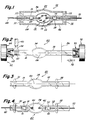
- Fig. 1 is a sectional view of a metal-halide discharge lamp embodying one form of the present invention.
- This lamp comprises an inner envelope of vitreous material and a tubular shroud of vitreous material surrounding the inner envelope.
- Fig. 2 is a schematic illustration of one step used in making the inner envelope portion of the lamp of Fig. 1.
- Fig. 3 shows the inner envelope portion of Fig. 2 after the fabrication steps depicted in Fig. 2 have been completed.
- Fig. 4 illustrates the manufacture of an arc tube incorporating the inner envelope of Fig. 3.
- Fig. 5 illustrates some of the method steps that are used for incorporating the shroud of Fig. 1 into the metal-halide lamp.
- Fig. 6 is a sectional view of a metal-halide lamp embodying a modified form of the invention.
- Fig. 7 is a sectional view of a vehicle head lamp that utilizes as its light source the lamp of Figs. 1-5.
- Fig. 8 is a simplified sectional view of another modified form of the invention.
- a metal-halide type of discharge lamp 10 that comprises an inner envelope 12 of a light-transmitting vitreous material, preferably quartz.
- the inner envelope 12 comprises a bulbous central portion 14 and two tubular portions 16 and 18 integral with the central portion 14 and projecting in opposite directions therefrom.
- a tubular shroud 20 Surrounding the inner envelope 12 is a tubular shroud 20, also of a vitreous material, preferably quartz.
- This shroud 20 has an enlarged central portion 22 disposed about the central portion 14 of the inner envelope. Projecting from this enlarged central portion 22 are two tubular portions 24 and 26 respectively surrounding the tubular portions 16 and 18 of the inner envelope.
- two disk members 30 and 32 Joining the shroud 20 to the inner envelope are two disk members 30 and 32 also of quartz. As will be explained in more detail, these disk members 30 and 32 are integral with the tubular portions 16 and 18 of the inner envelope and are joined at their respective outer peripheries to the surrounding regions of the shroud 20 to form vacuum-tight annular seals 33 and 35 between the disk members and the shroud.
- the tubular shroud 20 is spaced from the inner envelope 12 in the region between the two disk members 30 and 32, thus providing a sealed chamber 36 surrounding the inner envelope 12 and having an exterior wall defined by shroud 20 and end walls defined by disk members 30 and 32.
- this sealed chamber 36 is evacuated to a hard vacuum during fabrication of the lamp in a manner that will soon be described.
- this chamber includes a suitable getter 38 that is used in a conventional manner to assist in maintaining the hard vacuum in the chamber.
- the electrodes are preferably of tungsten or a mixture of tungsten and 1%-3% thorium oxide.
- the electrodes include rod portions 44 and 46, respectively, that extend outwardly from the gap between the electrodes into the tubular portions 16 and 18 of the inner envelope.
- a foil member 47 preferably of molybdenum, joined to the rod portion 44; and extending outwardly from the foil member there is an inlead 48, preferably of molybdenum, that is joined at its inner end to the foil member.
- the foil member 47, the inlead 48, and the rod portion 44 of the electrode are of a conventional form, and they are joined together in a conventional manner.
- the surrounding vitreous material of the envelope portion 16 while hot and softened, is collapsed about the foil, rod, and inlead structure in a conventional manner (such as disclosed, for example, in U.S. Patent 4,891,551 - Ahlgren et al) to form a leak-proof seal between the foil member and the surrounding vitreous material.
- a foil member 52 joined to an inlead 50 and to the rod portion 46 of electrode 42.
- the central portion 14 of the inner envelope 12 contains a fill containing mercury, a metal halide, and in some cases xenon gas.
- the operating pressure of the fill is in the range of about 2 to about 65 atmospheres. This fill is described in more detail in US Patent 4935668.
- one of the principal components of the fill is sodium iodine.
- the evacuated chamber 36 acts to produce an improved wall temperature of the inner envelope 12 by substantially eliminating the effects of gas conduction and convection in the region surrounding the inner envelope.
- the presence of the evacuated chamber makes this wall temperature higher and more uniform. This results in more metal halide being vaporized and maintained in the arcing region, which improves the efficiency of the lamp and the color of the emitted light.
- metal-halide lamps operating at low frequency there is a catephoresis effect that tends to sweep the metal halides into the end regions of the bulb (14), but in the illustrated lamp this effect is largely cancelled out by the higher temperatures produced in these end regions by the presence of the evacuated chamber 36 and its thermal insulating effect.
- This thermal insulating effect enables us, through proper choice of the size of the shroud, to operate a shroud of reasonable size at a sufficiently low temperature that its electronic conductivity remains very low. Maintaining this low electronic conductivity allows any sodium ions which diffuse through the inner envelope and evaporate to settle on the inside wall of the shroud without being electrically neutralized by wall conduction. It is believed that this enables the settled sodium ions to produce a strong electrical field which opposes the motion of subsequent migrating sodium ions, thereby reducing any further related sodium loss.
- Fig. 2 The first step in our method is illustrated in Fig. 2, where the tubular blank 60 from which the inner envelope is formed is shown mounted within a conventional glass lathe schematically illustrated at 61.
- This lathe comprises a headstock 62 and a collet chuck 64 for mounting the left-hand end of the tubular blank on the headstock so that the left-hand end is fixed against axial motion but is rotatable about the central longitudinal axis 66 of the blank 60.
- the lathe further comprises a tailstock 72 and a collet chuck 73 for mounting the right-hand end of the blank 60.
- the tailstock and the headstock are rotatably driven in synchronism about a common longitudinal axis coinciding with axis 66 by the same drive mechanism, thereby rotating the blank 60 about its longitudinal axis 66.
- the tailstock is also suitably mounted for selective movement parallel to this longitudinal axis 66, as indicated by the arrow 79.
- a burner 80 Positioned adjacent the left-hand tubular portion 16 of the blank 60 is a burner 80 that is adapted to develop a flame 82 that can be directed as shown against an axially -localized region 83 of the tubular portion 16. While the blank 60 is being slowly turned about its axis 66 by the lathe, the flame 82 heats the axially-localized region 83 about the entire periphery of the tubular portion 83 until the quartz in this region 83 has reached its softening point. The tailstock remains stationary during such heating; but when the quartz in region 83 is sufficiently softened, the tailstock is abruptly moved a short distance to the left, as indicated by arrow 79.
- This abrupt leftward motion causes compressive force to be applied to the softened region 83 in a direction along the axis 66, and such force has the effect of driving the softened quartz in this region 83 radially outward about the entire periphery of the tubular portion 16, thereby producing the disk formation shown at 30 in Fig. 3.
- These heating and force-applying steps can be readily controlled to consistently produce a disk formation of a predetermined outer diameter and a predetermined thickness along the length of axis 66.
- the two electrodes 40 and 42 and their inlead structures are installed by first suitably positioning each of these electrodes and inlead structures as shown in Fig. 4. Then the surrounding quartz (in region 90) is heated to its softening point and is collapsed about the conductive structure. The result is a sturdy mount for the inlead and the electrode and a good leak-proof seal between the foil member 47 or 52 and the surrounding quartz.
- This sealing of the foil member and mounting of the electrodes and inleads is a conventional operation, which is disclosed in greater detail in our aforesaid U.S. Patent 4,891,551.
- the fill, described hereinabove, that is present in the arc chamber 14 of the lamp assembly of Fig. 1 is installed in a conventional manner after one of the foil seals is made as above described but before the other foil seal is made.
- the tubular shroud 20 is installed as shown in Fig. 5.
- This shroud is positioned about the inner envelope of Fig. 4 so that predetermined portions 92 and 94 thereof are in alignment with the disk-shaped enlargements 30 and 32, respectively.
- Each of the disk-shaped enlargements has been formed by the operation of Fig. 2 in such a manner that its outer diameter is almost, but not quite, as large as the internal diameter of the shroud 20 in the aligned regions 92 or 94. Accordingly, there is a small clearance space about the outer periphery of each of the enlargements that allows the shroud 20 to be readily positioned in the desired position shown.
- the region 92 of the shroud is heated by flame 95 derived from a ring-type burner 96 that surrounds the region 92.
- flame 95 derived from a ring-type burner 96 that surrounds the region 92.
- the quartz of region 92 reaches its softening point and begins to contract under the influence of surface tension. This causes the softened region 92 to collapse about the outer periphery of the aligned disk-shaped enlargement 30, which, because of its proximity, has also been heated by flame 95.
- the softened shroud region 92 collapses about the outer periphery of the disk-shaped enlargement 30, an excellent seal is formed between shroud region 92 and the enlargement 30 about the entire outer periphery of the enlargement.
- the space 36 between the shroud 20 and the inner envelope 12 and between the disk-shaped enlargements 30 and 32 is evacuated. This is done by evacuating this space 36 with a suitable vacuum pump (not shown), which draws the contents of this space out through the small clearance space 97 surrounding the other disk-shaped enlargement 32.
- a suitable vacuum pump (not shown), which draws the contents of this space out through the small clearance space 97 surrounding the other disk-shaped enlargement 32.
- the intake of the pump is connected in a conventional manner between the tubular portion 18 of the inner envelope and the surrounding tubular portion 26 of the shroud in a location above the enlargement 32.) While such evacuation is taking place, the walls of space 36 are suitably heated to help drive off absorbed gases.
- a seal is made between the outer periphery of the disk-shaped enlargement 32 and the surrounding region 94 of the shroud 20.
- This seal is made in essentially the same manner as was used for making the first seal (at 92). More specifically, the shroud region 94 is heated to soften it, thereby causing it to collapse about the outer periphery of the disk-shaped enlargement and form a seal therewith. Because a vacuum is then present in the chamber 36 and also in the region above enlargement 32, there is a pressure differential on opposite sides of the shroud wall which promotes such collapse of the shroud about disk-shaped enlargement 32.
- a suitable getter 38 within chamber 36 is provided.
- This getter is introduced, preferably, before the shroud is assembled over the inner envelope.
- the getter comprises chips of zirconium-titanium alloy dispersed about the inner wall of the shroud. This material is a good getter for hydrogen.
- the locations (83 and 86 of Fig. 2) chosen for forming the disk-shaped enlargements 30 and 32 are such that the enlargements do not interfere with sealing the foils 47 and 52 within the tubular portions 16 and 18 of the inner envelope 12. More specifically, the chosen locations 83 and 86 are spaced axially outward from the location of the foils. But this axial spacing is kept sufficiently small so that the presence of the enlargements does not add materially to the overall length of the shrouded lamp.
- each seal is relatively remote from the foil seal at the same end of the envelope.
- the shroud-to-inner envelope seal at each end of the lamp is located radially-outward of the foil seal at the same end of the lamp by a distance approximately equal to the radial dimension R of the associated disk-shaped enlargement 30 or 32.
- This remoteness of the shroud seal from the foil seal is advantageous because it materially reduces the chances that the foil seal will be detrimentally affected by the heat involved in making the shroud seal.
- the lamp can be readily and quickly made with automated equipment.
- formation of the disk-shaped enlargements (30 and 32) is effected with the simple heating and force-application steps depicted in Fig. 2.
- steps are readily performed on the same machine (lathe 61) that was used for forming the bulbous central portion 14 of the inner envelope, which central portion 14 is preferably formed in a conventional manner by heating the starting tubular blank in this region and blowing the heat-softened quartz radially outward. While the blank is on this same machine and in the same position, the disk-shaped enlargements 30 and 32 are introduced, as above described.
- the seals between the shroud and the inner envelope are made by simple and brief heating operations (Fig.5), which cause the heat softened regions of the shroud to collapse the short distances required to effect high-quality seals to the disk-shaped enlargements 30 and 32.
- Figs. 1-5 While the embodiment of Figs. 1-5 includes disk-shaped enlargements (30 and 32) provided at both ends of the lamp for making the shroud-to-inner envelope seals, some of the advantages of our invention can still be realized if an enlargement of this character is provided only at one end of the lamp.
- the seal between the shroud and the inner envelope can be made in a conventional manner, for example, by allowing the heat-softened portion of the tubular shroud to shrink down to the tubular portion of the inner envelope that it seals to.
- Fig. 6 Such a lamp is illustrated in Fig. 6, where this conventional seal, designated 100, is shown at the left-hand end of the lamp.
- the tubular portion 24 of the shroud on the left hand end of the shroud is made only slightly larger than the left-hand-end tubular portion 16 of the inner envelope.
- the shroud is then slipped onto the inner envelope from the left hand end of the inner envelope so that the larger diameter end of the shroud slips over the bulbous portion 14 of the inner envelope and the disk enlargement 32. Then the seal 100 is made in a conventional manner.
- a surface of the shroud is coated with a reflective material to form a reflector which can be located close to the lamp.
- Such reflective material is indicated at 102 in Fig. 6.
- the shroud-to-inner envelope seal is the same as in Fig. 1.
- the conventional seal 100 of the immediately-preceding paragraph is present.
- the inner envelope and the shroud are both of identical quartz.
- our invention in its broader aspects contemplates the use of other vitreous material capable of withstanding the high temperatures developed by operation of the arc tube. It is usually very desirable to use the same material for the shroud and the inner envelope to avoid cracking or sealing problems that might arise because of different coefficients of thermal expansion of two different fused-together materials. But minor differences in the two materials can often be tolerated.
- the shroud quartz which has been heated with a high electric field applied thereto to remove any traces of sodium which can increase electronic conductivity.
- Such high resistance quartz is available from General Electric Company as its sodium-free quartz. This high resistance quartz can be sealed to an inner envelope of ordinary quartz without encountering significant problems of differential thermal expansion. The presence of such high resistance quartz in the shroud is believed to help block sodium loss through the inner envelope.
- the lamps described hereinabove are especially suited for forward lighting applications in a vehicle, such as an automobile, truck, bus, van or tractor.
- a vehicle such as an automobile, truck, bus, van or tractor.
- the aforesaid U.S. Patent 4935668 discloses several different ways in which a lamp of this general type is utilized for such forward lighting, and the present lamps are utilizable in the same ways.
- our lamp is shown at 10 within an automobile headlamp 110.
- This headlamp comprises a reflector 112, a lens member 114 at the front of the reflector, and lamp 10 in the space between the reflector and the lens.
- the reflector 112 has a rear section 118 having mounted thereon a connector 120 with rearwardly-projecting prongs 122 and 124 capable of being connected to an external electrical source of the vehicle.
- the reflector 112 has a focal point 126 on the axis 128 of the headlamp.
- the light source 10 is predeterminedly positioned within the reflector 112 so that its mid-portion approximately coincides with the focal point 126 of the reflector. In the embodiment illustrated in Fig. 7, the light source 10 is oriented with its longitudinal axis extending vertically and in a transverse manner relative to the axis 128 of the headlamp.
- the reflector 112 has a parabolic shape with a focal length in the range of about 6 mm to about 35 mm, with a preferred range of about 8 mm to about 30 mm.
- the lens 114 which is suitably mated to the front portion of the reflector, is of a transparent material, such as glass or a suitable plastic.
- the lens has a rear face preferably formed of prism members.
- the light source 10 is connected to the rear section of the reflector 112 by means of relatively heavy support wires 134 and 136 each having one end connected to one of the inleads 48 or 50 of the light source and its other end connected to one of the prongs 122 or 124.
- the light source 10 is energized via an electrical circuit that extends in series through the prongs and the support wires.
- the chamber 36 between the inner envelope and the shroud is evacuated to a hard vacuum
- our invention in its broader aspects comprehends lamps of essentially the same structure as shown in Figs. 1 and 6 except including in the chamber 36 a gas having appropriate properties.
- a gas having appropriate properties for example, in certain lamps it is desirable that a predetermined portion of the heat developed by operation of the arcing tube be transferred across the chamber 36 by conduction or convection rather than primarily by radiation, as when a hard vacuum is present.
- the chamber 36 can be filled with one of the following gases or mixtures thereof: argon, krypton, xenon, nitrogen, air, helium, and hydrogen. Typical charging pressures are in the range of 0 to 1500 torr.
- the invention in its broader aspects contemplates forming these enlargements after the electrodes and their inlead structures are incorporated and before the shroud 20 is installed.
Applications Claiming Priority (2)
| Application Number | Priority Date | Filing Date | Title |
|---|---|---|---|
| US54457190A | 1990-06-27 | 1990-06-27 | |
| US544571 | 1990-06-27 |
Publications (2)
| Publication Number | Publication Date |
|---|---|
| EP0465083A2 true EP0465083A2 (fr) | 1992-01-08 |
| EP0465083A3 EP0465083A3 (en) | 1993-01-20 |
Family
ID=24172730
Family Applications (1)
| Application Number | Title | Priority Date | Filing Date |
|---|---|---|---|
| EP19910305715 Withdrawn EP0465083A3 (en) | 1990-06-27 | 1991-06-25 | Discharge lamp with surrounding shroud and method of making such lamp |
Country Status (3)
| Country | Link |
|---|---|
| EP (1) | EP0465083A3 (fr) |
| JP (1) | JPH04229942A (fr) |
| CA (1) | CA2042143A1 (fr) |
Cited By (18)
| Publication number | Priority date | Publication date | Assignee | Title |
|---|---|---|---|---|
| US5253153A (en) * | 1992-09-16 | 1993-10-12 | General Electric Company | Vehicle headlamp comprising a metal-halide discharge lamp including an inner envelope and a surrounding shroud |
| EP0570068A1 (fr) * | 1992-05-11 | 1993-11-18 | Koninklijke Philips Electronics N.V. | Lampe à décharge à haute pression munie d'un culot |
| EP0612098A1 (fr) * | 1993-02-18 | 1994-08-24 | Patent-Treuhand-Gesellschaft für elektrische Glühlampen mbH | Lampe à décharge haute pression à culotage d'un seul côté |
| WO1994028576A1 (fr) * | 1993-05-25 | 1994-12-08 | Patent-Treuhand-Gesellschaft für elektrische Glühlampen mbH | Lampe a decharge sous haute pression et son procede de fabrication |
| US5388034A (en) * | 1992-09-16 | 1995-02-07 | General Electric Company | Vehicle headlamp comprising a discharge lamp including an inner envelope and a surrounding shroud |
| DE19545530A1 (de) * | 1994-12-06 | 1996-06-13 | Koito Mfg Co Ltd | Gasentladungslampenvorrichtung |
| EP1492146A2 (fr) * | 2003-06-05 | 2004-12-29 | Patent-Treuhand-Gesellschaft für elektrische Glühlampen mbH | Procédé pour la fabrication d'une lampe électrique avec ampoule exterieure |
| WO2005045880A1 (fr) | 2003-11-06 | 2005-05-19 | Guosheng Chai | Lampe a decharge haute resistance presentant un faible eblouissement et un rendement eleve pour vehicules |
| EP1720189A1 (fr) * | 2005-05-02 | 2006-11-08 | Patent-Treuhand-Gesellschaft für elektrische Glühlampen mbH | Lampe électrique à double paroi |
| WO2007014705A2 (fr) * | 2005-07-29 | 2007-02-08 | Patent-Treuhand-Gesellschaft für elektrische Glühlampen mbH | Lampe électrique à ampoule externe |
| US7221098B2 (en) | 2003-06-05 | 2007-05-22 | Patent-Treuhand-Gesellschaft für elektrische Glülampen mbH | Electric lamp with outer bulb and associated support body |
| US7253562B2 (en) | 2003-06-05 | 2007-08-07 | Patent-Treuhand-Gesellschaft fur electrische Glühlampen mbH | Lamp which is closed on two sides |
| DE10157868B4 (de) * | 2000-11-24 | 2007-08-30 | Koito Mfg. Co., Ltd. | Bogenentladungsröhre für Entladungsleuchte und Verfahren zur Herstellung derselben |
| EP1975975A1 (fr) | 2007-03-30 | 2008-10-01 | Patent-Treuhand-Gesellschaft Für Elektrische Glühlampen mbH | Unité de construction pour une lampe électrique dotée de pistons extérieurs |
| US7612503B2 (en) | 2004-11-23 | 2009-11-03 | Osram Gesellschaft Mit Beschraenkter Haftung | Electric lamp having an outer bulb |
| WO2010112314A1 (fr) * | 2009-04-01 | 2010-10-07 | Osram Gesellschaft mit beschränkter Haftung | Lampe électrique à ampoule externe |
| WO2011039033A1 (fr) * | 2009-10-02 | 2011-04-07 | Osram Gesellschaft mit beschränkter Haftung | Procédé de fabrication d'une lampe à décharge |
| WO2011104104A1 (fr) * | 2010-02-26 | 2011-09-01 | Osram Gesellschaft mit beschränkter Haftung | Lampe à décharge haute pression à ampoule externe de forme étagée |
Families Citing this family (12)
| Publication number | Priority date | Publication date | Assignee | Title |
|---|---|---|---|---|
| JPH0773851A (ja) * | 1993-09-01 | 1995-03-17 | Agency Of Ind Science & Technol | 放電ランプ |
| US5576598A (en) * | 1995-08-31 | 1996-11-19 | Osram Sylvania Inc. | Lamp with glass sleeve and method of making same |
| US7097528B2 (en) | 2002-12-27 | 2006-08-29 | Matsushita Electric Industrial Co., Ltd. | Method for producing a high pressure discharge lamp, with sealing portion having first and second glass members |
| US7038384B2 (en) | 2003-01-14 | 2006-05-02 | Matsushita Electric Industrial Co., Ltd. | High pressure discharge lamp, method for producing the same and lamp unit |
| US7097529B2 (en) | 2003-01-14 | 2006-08-29 | Matsushita Electric Industrial Co., Ltd. | Method for producing a high pressure discharge lamp, with sealing portion having first and second glass members |
| US7198534B2 (en) | 2003-01-24 | 2007-04-03 | Matsushita Electric Industrial Co., Ltd. | Method for manufacturing high-pressure discharge lamp, glass tube for high-pressure discharge lamp, and lamp element for high-pressure discharge lamp |
| DE102004036977A1 (de) | 2004-07-30 | 2006-02-16 | Patent-Treuhand-Gesellschaft für elektrische Glühlampen mbH | Zweiseitig verschlossene elektrische Lampe |
| DE102004056452A1 (de) * | 2004-11-23 | 2006-05-24 | Patent-Treuhand-Gesellschaft für elektrische Glühlampen mbH | Elektrische Lampe mit Außenkolben |
| DE102005012488A1 (de) * | 2005-02-28 | 2006-09-07 | Patent-Treuhand-Gesellschaft für elektrische Glühlampen mbH | Verfahren zur Herstellung einer Entladungsröhrenanordnung und eine derartige Entladungsbogenröhrenanordnung |
| JP4878984B2 (ja) * | 2006-10-24 | 2012-02-15 | ハリソン東芝ライティング株式会社 | 放電ランプおよび放電ランプの製造方法 |
| JP5186823B2 (ja) * | 2007-07-17 | 2013-04-24 | ウシオ電機株式会社 | 高圧放電ランプ及び高圧放電ランプを用いた光照射装置 |
| KR100918430B1 (ko) * | 2007-11-22 | 2009-09-24 | 조정열 | 이중관 구조의 램프 제조 방법 |
Citations (5)
| Publication number | Priority date | Publication date | Assignee | Title |
|---|---|---|---|---|
| US3867661A (en) * | 1973-10-19 | 1975-02-18 | Us Navy | Quick warm-up lamp |
| EP0062381A1 (fr) * | 1981-04-08 | 1982-10-13 | Koninklijke Philips Electronics N.V. | Lampe à décharge à haute pression |
| DE3904927A1 (de) * | 1988-02-18 | 1989-08-31 | Gen Electric | Metallhalogenidlampe mit vakuummantel fuer verbesserte leistung |
| DE3813421A1 (de) * | 1988-04-21 | 1989-11-02 | Philips Patentverwaltung | Hochdruck-quecksilberdampfentladungslampe |
| US4891555A (en) * | 1985-11-15 | 1990-01-02 | General Electric Company | Metal vapor discharge lamps |
-
1991
- 1991-05-09 CA CA 2042143 patent/CA2042143A1/fr not_active Abandoned
- 1991-06-25 JP JP17888191A patent/JPH04229942A/ja active Granted
- 1991-06-25 EP EP19910305715 patent/EP0465083A3/en not_active Withdrawn
Patent Citations (5)
| Publication number | Priority date | Publication date | Assignee | Title |
|---|---|---|---|---|
| US3867661A (en) * | 1973-10-19 | 1975-02-18 | Us Navy | Quick warm-up lamp |
| EP0062381A1 (fr) * | 1981-04-08 | 1982-10-13 | Koninklijke Philips Electronics N.V. | Lampe à décharge à haute pression |
| US4891555A (en) * | 1985-11-15 | 1990-01-02 | General Electric Company | Metal vapor discharge lamps |
| DE3904927A1 (de) * | 1988-02-18 | 1989-08-31 | Gen Electric | Metallhalogenidlampe mit vakuummantel fuer verbesserte leistung |
| DE3813421A1 (de) * | 1988-04-21 | 1989-11-02 | Philips Patentverwaltung | Hochdruck-quecksilberdampfentladungslampe |
Cited By (34)
| Publication number | Priority date | Publication date | Assignee | Title |
|---|---|---|---|---|
| EP0570068A1 (fr) * | 1992-05-11 | 1993-11-18 | Koninklijke Philips Electronics N.V. | Lampe à décharge à haute pression munie d'un culot |
| EP0588602A2 (fr) * | 1992-09-16 | 1994-03-23 | General Electric Company | Lampes |
| US5388034A (en) * | 1992-09-16 | 1995-02-07 | General Electric Company | Vehicle headlamp comprising a discharge lamp including an inner envelope and a surrounding shroud |
| EP0588602A3 (fr) * | 1992-09-16 | 1995-04-19 | Gen Electric | Lampes. |
| US5253153A (en) * | 1992-09-16 | 1993-10-12 | General Electric Company | Vehicle headlamp comprising a metal-halide discharge lamp including an inner envelope and a surrounding shroud |
| EP0612098A1 (fr) * | 1993-02-18 | 1994-08-24 | Patent-Treuhand-Gesellschaft für elektrische Glühlampen mbH | Lampe à décharge haute pression à culotage d'un seul côté |
| US5453654A (en) * | 1993-02-18 | 1995-09-26 | Patent-Treuhand Gesellschaft F. Elektrische Gluehlampen Mbh | Single-based high-pressure discharge lamp with a heat retention structure |
| US5726532A (en) * | 1993-05-25 | 1998-03-10 | Patent-Treuhand-Gesellschaft F. Elektrische Gluehlampen Mbh | High-pressure discharge lamp and process for producing it |
| WO1994028576A1 (fr) * | 1993-05-25 | 1994-12-08 | Patent-Treuhand-Gesellschaft für elektrische Glühlampen mbH | Lampe a decharge sous haute pression et son procede de fabrication |
| US5757110A (en) * | 1994-12-06 | 1998-05-26 | Koito Manufacturing Co., Ltd. | Electrical discharge lamp with ultraviolet filtering globe having rear end part supported insulating base |
| DE19545530B4 (de) * | 1994-12-06 | 2004-07-08 | Koito Mfg. Co., Ltd. | Gasentladungslampenvorrichtung |
| DE19545530A1 (de) * | 1994-12-06 | 1996-06-13 | Koito Mfg Co Ltd | Gasentladungslampenvorrichtung |
| DE10157868B4 (de) * | 2000-11-24 | 2007-08-30 | Koito Mfg. Co., Ltd. | Bogenentladungsröhre für Entladungsleuchte und Verfahren zur Herstellung derselben |
| EP1492146A2 (fr) * | 2003-06-05 | 2004-12-29 | Patent-Treuhand-Gesellschaft für elektrische Glühlampen mbH | Procédé pour la fabrication d'une lampe électrique avec ampoule exterieure |
| US7112116B2 (en) | 2003-06-05 | 2006-09-26 | Patent-Treuhand-Gesellschaft für elektrisch Glühlampen mbH | Process for producing an electric lamp with outer bulb |
| EP1492146A3 (fr) * | 2003-06-05 | 2010-09-08 | Patent-Treuhand-Gesellschaft für elektrische Glühlampen mbH | Procédé pour la fabrication d'une lampe électrique avec ampoule exterieure |
| US7221098B2 (en) | 2003-06-05 | 2007-05-22 | Patent-Treuhand-Gesellschaft für elektrische Glülampen mbH | Electric lamp with outer bulb and associated support body |
| US7253562B2 (en) | 2003-06-05 | 2007-08-07 | Patent-Treuhand-Gesellschaft fur electrische Glühlampen mbH | Lamp which is closed on two sides |
| WO2005045880A1 (fr) | 2003-11-06 | 2005-05-19 | Guosheng Chai | Lampe a decharge haute resistance presentant un faible eblouissement et un rendement eleve pour vehicules |
| EP1681707A1 (fr) * | 2003-11-06 | 2006-07-19 | Chai, Guosheng | Lampe a decharge haute resistance presentant un faible eblouissement et un rendement eleve pour vehicules |
| EP1681707A4 (fr) * | 2003-11-06 | 2010-11-03 | Guosheng Chai | Lampe a decharge haute resistance presentant un faible eblouissement et un rendement eleve pour vehicules |
| US7612503B2 (en) | 2004-11-23 | 2009-11-03 | Osram Gesellschaft Mit Beschraenkter Haftung | Electric lamp having an outer bulb |
| US7514873B2 (en) | 2005-05-02 | 2009-04-07 | Osram Gesellschaft Mit Beschraenkter Haftung | Electric lamp having an outer bulb |
| EP1720189A1 (fr) * | 2005-05-02 | 2006-11-08 | Patent-Treuhand-Gesellschaft für elektrische Glühlampen mbH | Lampe électrique à double paroi |
| WO2007014705A3 (fr) * | 2005-07-29 | 2007-05-31 | Patent Treuhand Ges Fuer Elektrische Gluehlampen Mbh | Lampe électrique à ampoule externe |
| WO2007014705A2 (fr) * | 2005-07-29 | 2007-02-08 | Patent-Treuhand-Gesellschaft für elektrische Glühlampen mbH | Lampe électrique à ampoule externe |
| EP1975975A1 (fr) | 2007-03-30 | 2008-10-01 | Patent-Treuhand-Gesellschaft Für Elektrische Glühlampen mbH | Unité de construction pour une lampe électrique dotée de pistons extérieurs |
| WO2010112314A1 (fr) * | 2009-04-01 | 2010-10-07 | Osram Gesellschaft mit beschränkter Haftung | Lampe électrique à ampoule externe |
| CN102388429A (zh) * | 2009-04-01 | 2012-03-21 | 奥斯兰姆有限公司 | 具有外泡壳的电灯 |
| WO2011039033A1 (fr) * | 2009-10-02 | 2011-04-07 | Osram Gesellschaft mit beschränkter Haftung | Procédé de fabrication d'une lampe à décharge |
| CN102549702A (zh) * | 2009-10-02 | 2012-07-04 | 欧司朗股份有限公司 | 用于制造放电灯的方法 |
| WO2011104104A1 (fr) * | 2010-02-26 | 2011-09-01 | Osram Gesellschaft mit beschränkter Haftung | Lampe à décharge haute pression à ampoule externe de forme étagée |
| CN102770937A (zh) * | 2010-02-26 | 2012-11-07 | 欧司朗股份有限公司 | 具有阶梯形的外灯壳的高压放电灯 |
| CN102770937B (zh) * | 2010-02-26 | 2016-02-10 | 欧司朗股份有限公司 | 具有阶梯形的外灯壳的高压放电灯 |
Also Published As
| Publication number | Publication date |
|---|---|
| JPH0565978B2 (fr) | 1993-09-20 |
| CA2042143A1 (fr) | 1991-12-28 |
| JPH04229942A (ja) | 1992-08-19 |
| EP0465083A3 (en) | 1993-01-20 |
Similar Documents
| Publication | Publication Date | Title |
|---|---|---|
| EP0465083A2 (fr) | Lampe à décharge avec récipients à doubles parvis et procédé pour la fabriquer | |
| US5598063A (en) | Means for supporting and sealing the lead structure of a lamp | |
| JPH0850881A (ja) | 電 球 | |
| US3448320A (en) | Electric lamp and method of manufacture | |
| US4631446A (en) | Single-ended high intensity discharge lamp | |
| EP0762478B1 (fr) | Lampe à manchon en verre | |
| US4668204A (en) | Single-ended high intensity discharge lamp and manufacture | |
| JP3213281B2 (ja) | 高圧放電ランプの製造方法 | |
| US2845557A (en) | Arc tube mounting | |
| WO1993013546A1 (fr) | Procedes de montage de filaments dans des capsules de lampe tubulaire a incandescence | |
| US5528106A (en) | Electric lamp with H-shaped pinched seal | |
| US6679746B2 (en) | Method for producing discharge lamp and discharge lamp | |
| KR100352918B1 (ko) | 램프와 램프의 제조방법 | |
| JPH07192695A (ja) | 放電ランプおよびその製造方法 | |
| JPH0613050A (ja) | 無電極高光度放電ランプの密閉構造 | |
| JP3463570B2 (ja) | 片口形メタルハライドランプおよびその製造方法 | |
| KR100382059B1 (ko) | 메탈할라이드램프제조방법 | |
| JPH0574420A (ja) | 金属蒸気放電灯 | |
| JPH03261066A (ja) | 一重管形高圧金属蒸気放電ランプ | |
| JPH10326592A (ja) | 多重管形蛍光ランプおよび照明装置 | |
| JPH09245737A (ja) | ランプ及び希ガス放電灯並びにその製造方法 | |
| JPH0432151A (ja) | 金属蒸気放電灯 | |
| JP2973229B2 (ja) | メタルハライドランプの製造方法 | |
| JPH02234342A (ja) | 複合発光管およびその製造方法 | |
| JPH06318434A (ja) | メタルハライドランプ発光管の製造方法 |
Legal Events
| Date | Code | Title | Description |
|---|---|---|---|
| PUAI | Public reference made under article 153(3) epc to a published international application that has entered the european phase |
Free format text: ORIGINAL CODE: 0009012 |
|
| AK | Designated contracting states |
Kind code of ref document: A2 Designated state(s): DE FR GB NL |
|
| PUAL | Search report despatched |
Free format text: ORIGINAL CODE: 0009013 |
|
| AK | Designated contracting states |
Kind code of ref document: A3 Designated state(s): DE FR GB NL |
|
| 17P | Request for examination filed |
Effective date: 19930708 |
|
| STAA | Information on the status of an ep patent application or granted ep patent |
Free format text: STATUS: THE APPLICATION HAS BEEN WITHDRAWN |
|
| 18W | Application withdrawn |
Withdrawal date: 19931213 |