EP0464970A1 - Verdrängermaschine nach dem Spiralprinzip - Google Patents
Verdrängermaschine nach dem Spiralprinzip Download PDFInfo
- Publication number
- EP0464970A1 EP0464970A1 EP91250141A EP91250141A EP0464970A1 EP 0464970 A1 EP0464970 A1 EP 0464970A1 EP 91250141 A EP91250141 A EP 91250141A EP 91250141 A EP91250141 A EP 91250141A EP 0464970 A1 EP0464970 A1 EP 0464970A1
- Authority
- EP
- European Patent Office
- Prior art keywords
- pressure fluid
- scroll
- fluid chamber
- end plate
- high pressure
- Prior art date
- Legal status (The legal status is an assumption and is not a legal conclusion. Google has not performed a legal analysis and makes no representation as to the accuracy of the status listed.)
- Granted
Links
Images


Classifications
-
- F—MECHANICAL ENGINEERING; LIGHTING; HEATING; WEAPONS; BLASTING
- F04—POSITIVE - DISPLACEMENT MACHINES FOR LIQUIDS; PUMPS FOR LIQUIDS OR ELASTIC FLUIDS
- F04C—ROTARY-PISTON, OR OSCILLATING-PISTON, POSITIVE-DISPLACEMENT MACHINES FOR LIQUIDS; ROTARY-PISTON, OR OSCILLATING-PISTON, POSITIVE-DISPLACEMENT PUMPS
- F04C18/00—Rotary-piston pumps specially adapted for elastic fluids
- F04C18/02—Rotary-piston pumps specially adapted for elastic fluids of arcuate-engagement type, i.e. with circular translatory movement of co-operating members, each member having the same number of teeth or tooth-equivalents
- F04C18/0207—Rotary-piston pumps specially adapted for elastic fluids of arcuate-engagement type, i.e. with circular translatory movement of co-operating members, each member having the same number of teeth or tooth-equivalents both members having co-operating elements in spiral form
- F04C18/0215—Rotary-piston pumps specially adapted for elastic fluids of arcuate-engagement type, i.e. with circular translatory movement of co-operating members, each member having the same number of teeth or tooth-equivalents both members having co-operating elements in spiral form where only one member is moving
-
- F—MECHANICAL ENGINEERING; LIGHTING; HEATING; WEAPONS; BLASTING
- F04—POSITIVE - DISPLACEMENT MACHINES FOR LIQUIDS; PUMPS FOR LIQUIDS OR ELASTIC FLUIDS
- F04C—ROTARY-PISTON, OR OSCILLATING-PISTON, POSITIVE-DISPLACEMENT MACHINES FOR LIQUIDS; ROTARY-PISTON, OR OSCILLATING-PISTON, POSITIVE-DISPLACEMENT PUMPS
- F04C23/00—Combinations of two or more pumps, each being of rotary-piston or oscillating-piston type, specially adapted for elastic fluids; Pumping installations specially adapted for elastic fluids; Multi-stage pumps specially adapted for elastic fluids
- F04C23/008—Hermetic pumps
Definitions
- the present invention relates to a scroll type fluid machinery used as a compressor, an expansion machine and the like.
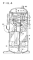
- Fig. 4 shows an example of a conventional scroll type compressor.
- a scroll type compression mechanism C is disposed at an upper part in a closed housing 8, and an electric motor 4 is disposed at a lower part thereof, and these are coupled interlocking with each other by means of a rotary shaft 5.
- the scroll type compression mechanism C is provided with a stationary scroll 1, a revolving scroll 2, a mechanism 3 for checking rotation on its axis such as an Oldham's link which allows revolution in a solar motion of the revolving scroll 2 but checks the rotation on its axis thereof, a frame 6 on which the stationary scroll 1 and the electric motor 4 are put in place, an upper bearing 71 and a lower bearing 72 which support the rotary shaft 5, and a rotating bearing 73 and a thrust bearing 74 which support the revolving scroll 2.
- the stationary scroll 1 consists of an end plate 11 and a spiral body 12, and a discharge port 13 and a discharge valve 17 which opens and closes the discharge port 13 are provided on the end plate 11.
- the revolving scroll 2 consists of an end plate 21, a spiral body 22 and a boss 23.
- a drive bushing 54 is supported in the boss 23 through the rotating bearing 73. Further, an eccentric pin 53 projected at the upper end of the rotary shaft 5 is supported rotatably in the drive bushing 54.
- Lubricating oil 81 stored at the bottom of the housing 8 is sucked up through an inlet hole 51 by means of centrifugal force generated by the rotation of the rotary shaft 5, and passes through an oil filler port 52 and lubricates the lower bearing 72, the eccentric pin 53, the upper bearing 71, the mechanism 3 for checking rotation on its axis, the rotating bearing 73, the thrust bearing 74 and the like, and is discharged to the bottom of the housing 8 through a chamber 61 and a drainage hole 62.
- gas enters into the housing 8 through a suction pipe 82 and cools the electric motor 4, and thereafter, is sucked into a plurality of closed spaces 24 which are delimited by having the stationary scroll 1 and the revolving scroll 2 with each other through a suction chamber 16 from a suction passage 15 provided in the stationary scroll 1. Then, the gas reaches a central part while being compressed as the volume of the closed spaces 24 is reduced by revolution in a solar motion of the revolving scroll 2, and pushes up a discharge valve 17 from a discharge port 13 and is discharged into a first discharge cavity 14. Then, the compressed gas enters into a second discharge cavity 19 through a hole 18 which is bored on a partition wall 31, and is discharged outside therefrom through a discharge pipe 83.
- 84 denotes a balance weight attached to the drive bushing 54.
- the gist of the present invention is as follows.
- the low pressure of the low pressure fluid which is introduced into the low pressure fluid chamber acts on the outer surface of the end plate of the stationary scroll. Thus, deformation of this end plate is prevented or reduced.
- a scroll type fluid machinery in which a pair of stationary scroll and revolving scroll having spiral elements set up on end plates, respectively, are engaged with each other so as to form closed spaces which vary the volume by revolution in a solar motion of the revolving scroll between both of these scrolls, and a high pressure fluid chamber is formed on the outside of the end plate of the stationary scroll, characterized in that an intermediate pressure fluid chamber is formed between the end plate of the stationary scroll and the high pressure fluid chamber, an intermediate pressure introduction hole communicating with the closed spaces is bored in the end plate of the stationary scroll, and the intermediate pressure fluid in the closed spaces is introduced into the intermediate pressure fluid chamber through the hole.
- the intermediate pressure fluid in the closed spaces is introduced into the intermediate pressure fluid chamber through the intermediate pressure introduction hole, and the intermediate pressure acts on the outer surface of the end plate of the stationary scroll.
- the fluid pressure in the closed spaces acting on the inner surface of the end plate is offset.
- Fig. 1 shows a first embodiment of the present invention.
- a cylindrical boss 30 surrounding a discharge port 13 is formed on an upper surface of an end plate 11 of a stationary scroll 1, and a tip of this boss 30 abuts against an underside of a partition wall 31 in a sealing manner.
- a first discharge cavity 32 is delimited by the inner circumferential surface of the boss 30, the outer surface of the end plate 11 and the inner surface of the partition wall 31, and a discharge valve 17 is disposed in the first discharge cavity 32.
- annular low pressure fluid chamber 35 is delimited by an inner circumferential surface of an annular flange 34 set up integrally on the periphery of the outer surface of the end plate 11, the outer circumferential surface of the cylindrical boss 30, the outer surface of the end plate 11 and the inner surface of the partition wall 31, and the low pressure fluid chamber 35 communicates with the space in the housing 8 at low pressure, viz., a low pressure fluid atmosphere through a notch 36 formed in the flange 34.
- the low pressure gas sucked into the housing 8 is introduced into the annular low pressure chamber 35 through the notch 36.
- the gas pressure acting on the outer surface of the end plate 11 of the stationary scroll 1 is reduced. Therefore, the force which presses the end plate 11 downward becomes remarkably smaller as compared with a conventional case, thus preventing or reducing downward deformation of the end plate 11.
- Fig. 2 shows a second embodiment of the present invention.
- annular gasket 37 is placed on the upper surface of the end plate 11 of the stationary scroll 1 so as to surround the discharge port 13 and an annular gasket 38 is also placed on an outer circumferential edge of the upper surface of the end plate 11 and these gaskets 37 and 38 are adhered to the underside of the partition wall 31.
- a discharge valve 17 is disposed in a second discharge cavity 19, and a hole 18 is opened and closed by means of this discharge valve 17. Also, a notch 40 is formed at a part of the gasket 38.
- a low pressure fluid chamber 41 is delimited by the outer circumferential surface of the gasket 37, the inner circumferential surface of the gasket 38, the top surface of the end plate 11 and the underside of the partition wall 31, and the low pressure chamber 41 communicates with the space in the housing 8 at low pressure, viz., a low pressure fluid atmosphere through the notch 40.
- the first discharge cavity 14 no longer exists, but the area of the low pressure fluid chamber 41 may be made larger than that in the first embodiment, and the structure can also be simplified.
- a low pressure fluid chamber is formed between an end plate of a stationary scroll and a high pressure fluid chamber, a low pressure of a low pressure fluid introduced into the low pressure fluid chamber acts on an outer surface of an end plate of a stationary scroll. Therefore, deformation of the end plate is prevented or reduced.
- FIG. 3 shows a third embodiment of the present invention.
- a cylindrical boss 30 surrounding the discharge port 13 is formed on the top surface of the end plate 11 of the stationary scroll 1, and the tip of this boss 30 abuts against the underside of the partition wall 31 in a sealing manner.
- a first discharge cavity 32 is delimited by the inner circumferential surface of the boss 30, the outer surface of the end plate 11 and the inner surface of the partition wall 31, and the discharge valve 17 is disposed in the first discharge cavity 32.
- annular intermediate pressure fluid chamber 135 is delimited by the inner circumferential surface of the annular flange 34 set up integrally on the periphery of the outer surface of the end plate 11, the outer circumferential surface of the cylindrical boss 30, the outer surface of the end plate 11 and the inner surface of the partition wall 31.
- This intermediate pressure fluid chamber 135 communicates with the closed spaces 24 during compression through an intermediate pressure introduction hole 136 which is bored in the end plate 11.
- the fluid pressure in the closed spaces 24 increases as going toward the center of the spiral, and the end plate 11 of the stationary scroll 1 is pressed upward by the fluid pressure in the closed spaces 24.
- gas at an intermediate pressure in the closed spaces 24 during compression is introduced into the annular intermediate pressure fluid chamber 135 through the gas intermediate pressure introduction hole 136, and the end plate 11 of the stationary scroll 1 is pressed downward by the intermediate pressure fluid in the intermediate pressure fluid chamber 135.
- the intermediate pressure MP in the closed small chamber 24 during compression is expressed as: where,
- a partition wall is provided between an end plate of a stationary scroll and a high pressure fluid chamber, and an intermediate pressure fluid chamber into which the intermediate pressure fluid in the closed spaces is introduced through an intermediate pressure introduction hole bored in the end plate is formed between the partition wall and the end plate of the stationary scroll.
Applications Claiming Priority (4)
| Application Number | Priority Date | Filing Date | Title |
|---|---|---|---|
| JP2179062A JP2778808B2 (ja) | 1990-07-06 | 1990-07-06 | スクロール型圧縮機 |
| JP2179063A JPH0466702A (ja) | 1990-07-06 | 1990-07-06 | スクロール型流体機械 |
| JP179063/90 | 1990-07-06 | ||
| JP179062/90 | 1990-07-06 |
Publications (2)
| Publication Number | Publication Date |
|---|---|
| EP0464970A1 true EP0464970A1 (de) | 1992-01-08 |
| EP0464970B1 EP0464970B1 (de) | 1996-10-23 |
Family
ID=26499033
Family Applications (1)
| Application Number | Title | Priority Date | Filing Date |
|---|---|---|---|
| EP91250141A Expired - Lifetime EP0464970B1 (de) | 1990-07-06 | 1991-05-30 | Verdrängermaschine nach dem Spiralprinzip |
Country Status (7)
| Country | Link |
|---|---|
| US (2) | US5186616A (de) |
| EP (1) | EP0464970B1 (de) |
| KR (1) | KR960000090B1 (de) |
| CN (1) | CN1019994C (de) |
| AU (1) | AU7822291A (de) |
| CA (1) | CA2043933C (de) |
| DE (1) | DE69122809T2 (de) |
Families Citing this family (24)
| Publication number | Priority date | Publication date | Assignee | Title |
|---|---|---|---|---|
| DE69604607T2 (de) * | 1995-03-13 | 2000-03-23 | Mitsubishi Heavy Ind Ltd | Spiralverdrängermaschine |
| JPH09303277A (ja) * | 1996-05-10 | 1997-11-25 | Sanyo Electric Co Ltd | スクロール圧縮機 |
| US5800141A (en) * | 1996-11-21 | 1998-09-01 | Copeland Corporation | Scroll machine with reverse rotation protection |
| US6146118A (en) * | 1998-06-22 | 2000-11-14 | Tecumseh Products Company | Oldham coupling for a scroll compressor |
| JP2005201114A (ja) * | 2004-01-14 | 2005-07-28 | Toyota Industries Corp | 圧縮機 |
| ES2579834T3 (es) | 2004-07-13 | 2016-08-17 | Tiax Llc | Sistema y método de refrigeración |
| JP4837331B2 (ja) * | 2005-08-11 | 2011-12-14 | 三菱電機株式会社 | スクロール流体機械の位置決め方法およびその装置、並びにスクロール流体機械の組み立て方法およびその装置 |
| US7988433B2 (en) | 2009-04-07 | 2011-08-02 | Emerson Climate Technologies, Inc. | Compressor having capacity modulation assembly |
| ITCO20110058A1 (it) | 2011-12-05 | 2013-06-06 | Nuovo Pignone Spa | Turbomacchina |
| US9651043B2 (en) | 2012-11-15 | 2017-05-16 | Emerson Climate Technologies, Inc. | Compressor valve system and assembly |
| US9249802B2 (en) | 2012-11-15 | 2016-02-02 | Emerson Climate Technologies, Inc. | Compressor |
| JP6328386B2 (ja) * | 2013-07-16 | 2018-05-23 | サンデンホールディングス株式会社 | スクロール型流体機械及びそのガスケット |
| CN104373346A (zh) * | 2013-08-14 | 2015-02-25 | 丹佛斯(天津)有限公司 | 涡旋压缩机以及其中压腔的密封方法和密封装置 |
| US9790940B2 (en) | 2015-03-19 | 2017-10-17 | Emerson Climate Technologies, Inc. | Variable volume ratio compressor |
| US10598180B2 (en) * | 2015-07-01 | 2020-03-24 | Emerson Climate Technologies, Inc. | Compressor with thermally-responsive injector |
| US10801495B2 (en) | 2016-09-08 | 2020-10-13 | Emerson Climate Technologies, Inc. | Oil flow through the bearings of a scroll compressor |
| US10890186B2 (en) | 2016-09-08 | 2021-01-12 | Emerson Climate Technologies, Inc. | Compressor |
| US10753352B2 (en) | 2017-02-07 | 2020-08-25 | Emerson Climate Technologies, Inc. | Compressor discharge valve assembly |
| JP6500935B2 (ja) | 2017-05-12 | 2019-04-17 | ダイキン工業株式会社 | スクロール圧縮機 |
| US11022119B2 (en) | 2017-10-03 | 2021-06-01 | Emerson Climate Technologies, Inc. | Variable volume ratio compressor |
| US10962008B2 (en) | 2017-12-15 | 2021-03-30 | Emerson Climate Technologies, Inc. | Variable volume ratio compressor |
| US10995753B2 (en) | 2018-05-17 | 2021-05-04 | Emerson Climate Technologies, Inc. | Compressor having capacity modulation assembly |
| US11655813B2 (en) | 2021-07-29 | 2023-05-23 | Emerson Climate Technologies, Inc. | Compressor modulation system with multi-way valve |
| US11846287B1 (en) | 2022-08-11 | 2023-12-19 | Copeland Lp | Scroll compressor with center hub |
Citations (2)
| Publication number | Priority date | Publication date | Assignee | Title |
|---|---|---|---|---|
| EP0037728A1 (de) * | 1980-04-05 | 1981-10-14 | Sanden Corporation | Fluidumverdichter mit Exzenterspiralelementen |
| EP0322894A2 (de) * | 1987-12-28 | 1989-07-05 | Matsushita Electric Industrial Co., Ltd. | Spiralverdichter |
Family Cites Families (11)
| Publication number | Priority date | Publication date | Assignee | Title |
|---|---|---|---|---|
| US3874827A (en) * | 1973-10-23 | 1975-04-01 | Niels O Young | Positive displacement scroll apparatus with axially radially compliant scroll member |
| JPS6198987A (ja) * | 1984-10-19 | 1986-05-17 | Hitachi Ltd | 密閉形スクロ−ル圧縮機 |
| JPS62163678A (ja) * | 1986-01-14 | 1987-07-20 | Taiyo Kagaku Kk | 罐詰嗜好飲料の製造法 |
| US4767293A (en) * | 1986-08-22 | 1988-08-30 | Copeland Corporation | Scroll-type machine with axially compliant mounting |
| JP2692694B2 (ja) * | 1987-05-25 | 1997-12-17 | 日本電信電話株式会社 | 光ファイバレーザ装置 |
| JPS6463678A (en) * | 1987-09-04 | 1989-03-09 | Toshiba Corp | Scroll compressor |
| JPH01195987A (ja) * | 1988-02-01 | 1989-08-07 | Daikin Ind Ltd | スクロール形圧縮機 |
| JPH068632B2 (ja) * | 1988-09-28 | 1994-02-02 | ダイキン工業株式会社 | スクロール形流体機械 |
| JPH02125986A (ja) * | 1988-11-05 | 1990-05-14 | Daikin Ind Ltd | スクロール形圧縮機 |
| JPH02149783A (ja) * | 1988-11-30 | 1990-06-08 | Toshiba Corp | スクロール形流体機械 |
| JPH06198987A (ja) * | 1992-12-28 | 1994-07-19 | Canon Inc | 記録装置 |
-
1991
- 1991-05-30 EP EP91250141A patent/EP0464970B1/de not_active Expired - Lifetime
- 1991-05-30 DE DE69122809T patent/DE69122809T2/de not_active Expired - Fee Related
- 1991-05-31 US US07/708,714 patent/US5186616A/en not_active Expired - Lifetime
- 1991-06-05 CA CA002043933A patent/CA2043933C/en not_active Expired - Fee Related
- 1991-06-06 AU AU78222/91A patent/AU7822291A/en not_active Abandoned
- 1991-06-29 CN CN91104302A patent/CN1019994C/zh not_active Expired - Fee Related
- 1991-07-06 KR KR1019910011451A patent/KR960000090B1/ko not_active IP Right Cessation
-
1992
- 1992-11-06 US US07/972,911 patent/US5330463A/en not_active Expired - Fee Related
Patent Citations (2)
| Publication number | Priority date | Publication date | Assignee | Title |
|---|---|---|---|---|
| EP0037728A1 (de) * | 1980-04-05 | 1981-10-14 | Sanden Corporation | Fluidumverdichter mit Exzenterspiralelementen |
| EP0322894A2 (de) * | 1987-12-28 | 1989-07-05 | Matsushita Electric Industrial Co., Ltd. | Spiralverdichter |
Non-Patent Citations (4)
| Title |
|---|
| PATENT ABSTRACTS OF JAPAN, vol. 13, no. 258 (M-838)(3606) 15 June 1989; & JP-A-1 063 678 (TOSHIBA) 9 March 1989 * |
| PATENT ABSTRACTS OF JAPAN, vol. 13, no. 489 (M-888)(3837) 7 November 1989; & JP-A-1 195 987 (DAIKIN) 7 August 1989 * |
| PATENT ABSTRACTS OF JAPAN, vol. 14, no. 291 (M-989)(4234) 22 June 1990; & JP-A-2 091 488 (DAIKIN) 30 March 1990 * |
| PATENT ABSTRACTS OF JAPAN, vol. 14, no. 395 (M-1016)(4338) 27 August 1990; & JP-A-2 149 783 (TOSHIBA) 8 June 1990 * |
Also Published As
| Publication number | Publication date |
|---|---|
| KR960000090B1 (ko) | 1996-01-03 |
| US5186616A (en) | 1993-02-16 |
| DE69122809T2 (de) | 1997-03-27 |
| CN1057889A (zh) | 1992-01-15 |
| US5330463A (en) | 1994-07-19 |
| AU7822291A (en) | 1992-01-09 |
| CA2043933A1 (en) | 1992-01-07 |
| KR920002936A (ko) | 1992-02-28 |
| CN1019994C (zh) | 1993-03-03 |
| CA2043933C (en) | 1996-02-13 |
| EP0464970B1 (de) | 1996-10-23 |
| DE69122809D1 (de) | 1996-11-28 |
Similar Documents
| Publication | Publication Date | Title |
|---|---|---|
| US5186616A (en) | Scroll type fluid machinery with reduced pressure biasing the stationary scroll | |
| US6419457B1 (en) | Dual volume-ratio scroll machine | |
| US8475140B2 (en) | Dual volume-ratio scroll machine | |
| USRE35216E (en) | Scroll machine with floating seal | |
| EP0479421A1 (de) | Spiralverdichter mit schwimmender Abdichtung | |
| US6439867B1 (en) | Scroll compressor having a clearance for the oldham coupling | |
| US4548555A (en) | Scroll type fluid displacement apparatus with nonuniform scroll height | |
| US5435707A (en) | Scroll-type compressor with an elastically deformable top plate or end plate | |
| EP0475538B1 (de) | Spiralverdrängungsanlage für Fluid | |
| US6231324B1 (en) | Oldham coupling for scroll machine | |
| EP0510782B1 (de) | Spiralverdichter | |
| US5848883A (en) | Scroll compressor having a back pressure partitioning member | |
| EP0471425A1 (de) | Strömungsmaschine in Spiralbauweise | |
| JPH0378586A (ja) | スクロール型流体装置 | |
| JPH0466701A (ja) | スクロール型圧縮機 | |
| JPH04362202A (ja) | スクロール型流体機械 | |
| JPH06137283A (ja) | スクロール型流体機械 | |
| AU8786398A (en) | Compressor |
Legal Events
| Date | Code | Title | Description |
|---|---|---|---|
| PUAI | Public reference made under article 153(3) epc to a published international application that has entered the european phase |
Free format text: ORIGINAL CODE: 0009012 |
|
| AK | Designated contracting states |
Kind code of ref document: A1 Designated state(s): DE FR GB |
|
| 17P | Request for examination filed |
Effective date: 19920422 |
|
| 17Q | First examination report despatched |
Effective date: 19921223 |
|
| GRAG | Despatch of communication of intention to grant |
Free format text: ORIGINAL CODE: EPIDOS AGRA |
|
| GRAG | Despatch of communication of intention to grant |
Free format text: ORIGINAL CODE: EPIDOS AGRA |
|
| GRAG | Despatch of communication of intention to grant |
Free format text: ORIGINAL CODE: EPIDOS AGRA |
|
| GRAH | Despatch of communication of intention to grant a patent |
Free format text: ORIGINAL CODE: EPIDOS IGRA |
|
| GRAH | Despatch of communication of intention to grant a patent |
Free format text: ORIGINAL CODE: EPIDOS IGRA |
|
| GRAA | (expected) grant |
Free format text: ORIGINAL CODE: 0009210 |
|
| AK | Designated contracting states |
Kind code of ref document: B1 Designated state(s): DE FR GB |
|
| ET | Fr: translation filed | ||
| REF | Corresponds to: |
Ref document number: 69122809 Country of ref document: DE Date of ref document: 19961128 |
|
| PLBE | No opposition filed within time limit |
Free format text: ORIGINAL CODE: 0009261 |
|
| STAA | Information on the status of an ep patent application or granted ep patent |
Free format text: STATUS: NO OPPOSITION FILED WITHIN TIME LIMIT |
|
| 26N | No opposition filed | ||
| PGFP | Annual fee paid to national office [announced via postgrant information from national office to epo] |
Ref country code: FR Payment date: 20010518 Year of fee payment: 11 |
|
| PGFP | Annual fee paid to national office [announced via postgrant information from national office to epo] |
Ref country code: DE Payment date: 20010522 Year of fee payment: 11 |
|
| PGFP | Annual fee paid to national office [announced via postgrant information from national office to epo] |
Ref country code: GB Payment date: 20010530 Year of fee payment: 11 |
|
| REG | Reference to a national code |
Ref country code: GB Ref legal event code: IF02 |
|
| PG25 | Lapsed in a contracting state [announced via postgrant information from national office to epo] |
Ref country code: GB Free format text: LAPSE BECAUSE OF NON-PAYMENT OF DUE FEES Effective date: 20020530 |
|
| PG25 | Lapsed in a contracting state [announced via postgrant information from national office to epo] |
Ref country code: DE Free format text: LAPSE BECAUSE OF NON-PAYMENT OF DUE FEES Effective date: 20021203 |
|
| GBPC | Gb: european patent ceased through non-payment of renewal fee |
Effective date: 20020530 |
|
| PG25 | Lapsed in a contracting state [announced via postgrant information from national office to epo] |
Ref country code: FR Free format text: LAPSE BECAUSE OF NON-PAYMENT OF DUE FEES Effective date: 20030131 |
|
| REG | Reference to a national code |
Ref country code: FR Ref legal event code: ST |