EP0464384B1 - Selbstentlüftbarer Flaschenverschluss - Google Patents
Selbstentlüftbarer Flaschenverschluss Download PDFInfo
- Publication number
- EP0464384B1 EP0464384B1 EP91109135A EP91109135A EP0464384B1 EP 0464384 B1 EP0464384 B1 EP 0464384B1 EP 91109135 A EP91109135 A EP 91109135A EP 91109135 A EP91109135 A EP 91109135A EP 0464384 B1 EP0464384 B1 EP 0464384B1
- Authority
- EP
- European Patent Office
- Prior art keywords
- seal
- screw cap
- mouth
- bottle
- cover plate
- Prior art date
- Legal status (The legal status is an assumption and is not a legal conclusion. Google has not performed a legal analysis and makes no representation as to the accuracy of the status listed.)
- Expired - Lifetime
Links
- 238000013022 venting Methods 0.000 title claims abstract description 8
- 238000007789 sealing Methods 0.000 claims abstract description 47
- 239000012528 membrane Substances 0.000 claims abstract description 4
- 239000000463 material Substances 0.000 claims description 7
- 230000000284 resting effect Effects 0.000 abstract description 5
- 230000006378 damage Effects 0.000 abstract description 3
- 230000007704 transition Effects 0.000 abstract description 3
- 230000000717 retained effect Effects 0.000 abstract 1
- 238000005452 bending Methods 0.000 description 3
- 238000004519 manufacturing process Methods 0.000 description 3
- CURLTUGMZLYLDI-UHFFFAOYSA-N Carbon dioxide Chemical compound O=C=O CURLTUGMZLYLDI-UHFFFAOYSA-N 0.000 description 2
- 230000001954 sterilising effect Effects 0.000 description 2
- 238000004659 sterilization and disinfection Methods 0.000 description 2
- 238000009423 ventilation Methods 0.000 description 2
- 241001411320 Eriogonum inflatum Species 0.000 description 1
- 235000013361 beverage Nutrition 0.000 description 1
- 229910002092 carbon dioxide Inorganic materials 0.000 description 1
- 239000001569 carbon dioxide Substances 0.000 description 1
- 235000014171 carbonated beverage Nutrition 0.000 description 1
- 230000006735 deficit Effects 0.000 description 1
- 230000005489 elastic deformation Effects 0.000 description 1
- 239000000945 filler Substances 0.000 description 1
- 238000000034 method Methods 0.000 description 1
- 210000002445 nipple Anatomy 0.000 description 1
- 230000000630 rising effect Effects 0.000 description 1
- 230000035939 shock Effects 0.000 description 1
- 239000007779 soft material Substances 0.000 description 1
Images


Classifications
-
- B—PERFORMING OPERATIONS; TRANSPORTING
- B65—CONVEYING; PACKING; STORING; HANDLING THIN OR FILAMENTARY MATERIAL
- B65D—CONTAINERS FOR STORAGE OR TRANSPORT OF ARTICLES OR MATERIALS, e.g. BAGS, BARRELS, BOTTLES, BOXES, CANS, CARTONS, CRATES, DRUMS, JARS, TANKS, HOPPERS, FORWARDING CONTAINERS; ACCESSORIES, CLOSURES, OR FITTINGS THEREFOR; PACKAGING ELEMENTS; PACKAGES
- B65D41/00—Caps, e.g. crown caps or crown seals, i.e. members having parts arranged for engagement with the external periphery of a neck or wall defining a pouring opening or discharge aperture; Protective cap-like covers for closure members, e.g. decorative covers of metal foil or paper
- B65D41/02—Caps or cap-like covers without lines of weakness, tearing strips, tags, or like opening or removal devices
- B65D41/04—Threaded or like caps or cap-like covers secured by rotation
- B65D41/0407—Threaded or like caps or cap-like covers secured by rotation with integral sealing means
- B65D41/0414—Threaded or like caps or cap-like covers secured by rotation with integral sealing means formed by a plug, collar, flange, rib or the like contacting the internal surface of a container neck
- B65D41/0421—Threaded or like caps or cap-like covers secured by rotation with integral sealing means formed by a plug, collar, flange, rib or the like contacting the internal surface of a container neck and combined with integral sealing means contacting other surfaces of a container neck
-
- B—PERFORMING OPERATIONS; TRANSPORTING
- B65—CONVEYING; PACKING; STORING; HANDLING THIN OR FILAMENTARY MATERIAL
- B65D—CONTAINERS FOR STORAGE OR TRANSPORT OF ARTICLES OR MATERIALS, e.g. BAGS, BARRELS, BOTTLES, BOXES, CANS, CARTONS, CRATES, DRUMS, JARS, TANKS, HOPPERS, FORWARDING CONTAINERS; ACCESSORIES, CLOSURES, OR FITTINGS THEREFOR; PACKAGING ELEMENTS; PACKAGES
- B65D41/00—Caps, e.g. crown caps or crown seals, i.e. members having parts arranged for engagement with the external periphery of a neck or wall defining a pouring opening or discharge aperture; Protective cap-like covers for closure members, e.g. decorative covers of metal foil or paper
- B65D41/02—Caps or cap-like covers without lines of weakness, tearing strips, tags, or like opening or removal devices
- B65D41/04—Threaded or like caps or cap-like covers secured by rotation
-
- B—PERFORMING OPERATIONS; TRANSPORTING
- B65—CONVEYING; PACKING; STORING; HANDLING THIN OR FILAMENTARY MATERIAL
- B65D—CONTAINERS FOR STORAGE OR TRANSPORT OF ARTICLES OR MATERIALS, e.g. BAGS, BARRELS, BOTTLES, BOXES, CANS, CARTONS, CRATES, DRUMS, JARS, TANKS, HOPPERS, FORWARDING CONTAINERS; ACCESSORIES, CLOSURES, OR FITTINGS THEREFOR; PACKAGING ELEMENTS; PACKAGES
- B65D41/00—Caps, e.g. crown caps or crown seals, i.e. members having parts arranged for engagement with the external periphery of a neck or wall defining a pouring opening or discharge aperture; Protective cap-like covers for closure members, e.g. decorative covers of metal foil or paper
- B65D41/32—Caps or cap-like covers with lines of weakness, tearing-strips, tags, or like opening or removal devices, e.g. to facilitate formation of pouring openings
- B65D41/34—Threaded or like caps or cap-like covers provided with tamper elements formed in, or attached to, the closure skirt
- B65D41/3442—Threaded or like caps or cap-like covers provided with tamper elements formed in, or attached to, the closure skirt with rigid bead or projections formed on the tamper element and coacting with bead or projections on the container
- B65D41/3447—Threaded or like caps or cap-like covers provided with tamper elements formed in, or attached to, the closure skirt with rigid bead or projections formed on the tamper element and coacting with bead or projections on the container the tamper element being integrally connected to the closure by means of bridges
-
- B—PERFORMING OPERATIONS; TRANSPORTING
- B65—CONVEYING; PACKING; STORING; HANDLING THIN OR FILAMENTARY MATERIAL
- B65D—CONTAINERS FOR STORAGE OR TRANSPORT OF ARTICLES OR MATERIALS, e.g. BAGS, BARRELS, BOTTLES, BOXES, CANS, CARTONS, CRATES, DRUMS, JARS, TANKS, HOPPERS, FORWARDING CONTAINERS; ACCESSORIES, CLOSURES, OR FITTINGS THEREFOR; PACKAGING ELEMENTS; PACKAGES
- B65D51/00—Closures not otherwise provided for
- B65D51/16—Closures not otherwise provided for with means for venting air or gas
- B65D51/1633—Closures not otherwise provided for with means for venting air or gas whereby venting occurs by automatic opening of the closure, container or other element
- B65D51/1661—Closures not otherwise provided for with means for venting air or gas whereby venting occurs by automatic opening of the closure, container or other element by means of a passage for the escape of gas between the closure and the lip of the container mouth
Definitions
- the invention relates to a closure cap for a bottle or a similar hollow container, which consists of a cover plate which engages over the mouth of the bottle and a collar which is integrally formed thereon and can be locked on the mouthpiece, with a first seal resting on the end face of the mouthpiece and a second seal can be pressed onto the inner surface of the cover and the closure cap has an elastically deformable zone, through which the cover plate for venting the interior of the bottle can be arched out in the manner of a membrane depending on the pressure prevailing therein, and the elastically deformable zone of the closure cap by radial outside the first seal, preferably circumferential grooves are formed in the cover plate on the inside and / or the outside thereof.
- the cap of this bottle stopper consists of a plastic, the bending stiffness of which changes as a function of temperature, so that when the temperature rises above room temperature, the cover plate can be arched out by the internal pressure of the container rising due to the temperature increase.
- the elastically deformable zone is thus formed by an annular bending zone in the transition area between the collar and the cover plate.
- a bottle Due to the first seal resting on the end face of the mouthpiece and the second seal resting against the inner surface of the mouth, a bottle can be reliably closed with this cap, but an automatic pressure reduction in the interior of the bottle is only given when the pressure rises due to increased outside temperature. If, on the other hand, a bottle filled with a carbonated beverage and secured with such a closure cap is shaken at room temperature, the internal pressure sometimes rises to a considerable extent as a result of the carbon dioxide released. However, since the bending zone is not effective in this case, the cover plate is also not lifted off and the internal pressure is therefore not reduced. When the bottle is opened, the beverage can splash out of it, and the bottle can also be destroyed by excessive pressure.
- a closure cap is made from a soft material, unevenness at the bottle mouth is compensated, one soft cap can be easily turned over, so that a tight seal is no longer given. And in the case of a closure cap made of a hard material, a tight closure can often not be achieved, since the seals do not lie against the mouthpiece to a sufficient extent.
- the known cap is therefore not practical and can only be used to a limited extent.
- a container closure according to the preamble of claim 1 is known from US-A-30 47 144.
- This closure is intended for filled packages that are sterilized, so that it is subjected to negative pressure.
- the two seals arranged next to each other, designed as nipples, are simultaneously lifted during the sterilization process due to the sometimes high excess pressure that builds up in the interior of the container; when the sterilization temperature is reduced, the cover plate in turn rests on the inner surface and the mouth of the container. As it cools further, the closure is pressed by the vacuum that builds up.
- the design of the first seal only gives a linear contact on the mouth and therefore an inadequate seal, this closure is not suitable for containers that are constantly under pressure, since sufficient sealing of the container interior over a longer period of time Period is not guaranteed.
- the object of the invention is therefore to provide a cap of the aforementioned type, which is not only easy and economical to manufacture, but by means of the automatic ventilation depending on the internal pressure build-up in a bottle and regardless of the Outside temperature is guaranteed. Furthermore, it should be achieved that even with different mouth diameters and / or bottle mouths damaged by the filling tube, for example, reliable sealing of the bottle can be achieved, even after venting, and that venting takes place at a selectable limit value.
- the cap thus acting as a pressure relief valve should be able to be designed for different overpressures, depending on the intended use, it should also be easy to open, and a bottle should be able to be closed repeatedly with this cap without difficulty.
- this is achieved in that in the transition region between the collar and the cover plate there is either a third seal which protrudes in the direction of the mouthpiece of the bottle and which is adjustable up to an either next to the elastically deformable zone or at a short distance therefrom In the interior of the bottle, excess pressure builds up sealingly against its mouthpiece when the first and second seals are already ineffective due to excess pressure.
- the first seal resting on the end face of the mouthpiece by means of two concentrically arranged sealing lips which are inclined inwardly in the axial direction of the mouthpiece, preferably at an angle ⁇ of 10 ° -15 ° to the longitudinal axis of the bottle, and the radially inner sealing lip in To allow axial direction to protrude beyond the radially outer sealing lip, the two sealing lips being conically tapered in cross-section in the direction of the mouthpiece and each having an inwardly inclined, preferably arranged in one plane and at an angle ⁇ of 20 ° to 40 °, preferably of 25 °, should have contact surface running to the level of the top cap.
- the first seal can also be formed by a sealing ring inserted into the sealing cap, and to hold the sealing ring, the cover plate should have a circumferential projection or protruding webs, preferably provided with a concavely curved support surface.
- the second cooperating with the inner surface of the mouthpiece seal of the cover plate should also be designed in the form of a sealing lip extending inclined to the longitudinal axis of the bottle, the inward surface of the surface concentric with the collar of the closure cap and its facing
- the lateral surface should be designed at an angle ⁇ of 10 ° to 15 °, preferably at an angle of 12 °, in the axial direction of the mouthpiece and should be inclined inwards.
- the third seal of the closure cap by means of a sealing lip protruding in the direction of the mouthpiece of the bottle, which should have an approximately trapezoidal cross-section and should have an outwardly inclined contact surface.
- the elastically deformable zone of the closure cap is to be formed by a circumferential groove which is worked into the inside of the cover cap and is approximately semicircular and merges into the outer surface of the sealing lip of the third seal.
- the side of the top cap facing the mouthpiece of the bottle has a symmetrical spherical cap-shaped curvature in the inner region between the second seal and that a retaining ring is formed on the mouthpiece of the bottle and is formed on the free end of the collar of the closure cap .
- a closure cap according to the invention is formed by incorporating an elastically deformable zone into its cover plate and forming a third seal in the radially outer region of the cover plate, So it is possible to vent the interior of a bottle equipped with this cap automatically, depending on the prevailing internal pressure and regardless of the respective outside temperature, and thus to reduce the pressure, so that impairments to the contents and / or destruction of the bottles are reliably avoided .
- the first seal in turn, is pressed against the end face of the mouthpiece by the cover plate returning to the starting position, and the second seal, by means of which dimensional tolerances and damage can also be compensated for, are pressed against the inner jacket surface thereof, a secure closure of the bottle is therefore given, even with repeated venting.
- the third outer seal also ensures that the closure cap is only effective as a pressure relief valve at a certain selectable internal pressure. And since the elastic zone can be easily molded into the cover plate during its manufacture, an economical manufacture of the proposed closure cap, which can be used for all bottles or similar hollow containers in circulation and can be processed on conventional closure machines, is also guaranteed.
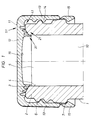
- the closure cap shown in FIGS. 1 to 3 and designated 11 consists of a flat cover plate 12 and a collar 13 formed thereon and is screwed onto the mouthpiece 2 of a bottle 1 provided with an external thread 6 in order to close its mouth 5.
- the collar 13 is provided with an internal thread 14.
- a collar 15 is attached to the collar 13, which engages behind a collar 7 formed on the mouthpiece 2 in the closed state.
- a first seal 21, which cooperates with the end face 3 of the mouthpiece 2 is a second seal 31, which can be pressed onto the inner lateral surface 4 of the closure cap 11 made of a plastic material, as well as a third seal 41, which bears against the mouthpiece 2 in the outer region thereof.
- the closure cap 11 is provided with an elastically deformable zone 51 arranged between the first seal 21 and the third seal 41, by means of which an automatic and reliable ventilation of the interior 10 of the bottle 1 is accomplished as a function of the internal pressure prevailing therein.
- the first seal 21 consists of two concentrically arranged sealing lips 22 and 23, which are inclined inwards at an angle ⁇ of 20 ° to the longitudinal axis of the bottle 1.
- the sealing lips 22 and 23, which have a conically tapering cross section, are provided at their ends with contact surfaces 24 and 25 which run in one plane and are inclined at an angle ⁇ of 25 ° to the plane of the cover plate 12. In this way, a secure contact on the end face 3 of the mouthpiece 2 is guaranteed.
- the second seal 31 is also formed by a sealing lip 32.
- the inward jacket surface 33 of the sealing lip 32 runs concentrically to the collar 13, the outer jacket surface 34 facing it, however, is inclined inwardly at an angle ⁇ of 12 ° in the axial direction of the mouthpiece 2. This ensures that even with different inside diameters of the mouth 5 of the mouthpiece 2 and / or at z. B. caused by a filler tube nevertheless a sealing contact of the sealing lip 32 on the inner surface 4 of the mouthpiece 2 is given.
- the sealing lip 32 is namely pressed against the mouthpiece 4 by the pressure prevailing in the interior 10 of the bottle 1.
- the third seal 41 also consists of a sealing lip 42, which is approximately trapezoidal in cross-section and has an outwardly inclined contact surface 43.
- the sealing lip 42 interacts with the outer part of the mouthpiece 2 and additionally seals the interior 10 of the bottle 1. Even if the first seal 21 and the second seal 31 no longer lie sealingly against the end face 3 or the inner surface area 4 of the mouthpiece 2 due to a slight excess pressure in the bottle 1, a tight seal is nevertheless provided.
- the elastically deformable zone 51 is in the form of a groove in the cover plate 12 52 incorporated.
- the groove 52 has a semicircular cross section and merges into the outer lateral surface of the outer sealing lip 23 of the first seal 21 and into the inner lateral surface of the sealing lip 42 of the third seal 41.
- an insert 53 made of an elastically deformable material can also be used in the region of the elastically deformable zone 51.
- the deformability of the cover plate 12 can be adapted to the particular application of the closure cap 11.
- the shape and size of the seals 21, 31 and 41 and in particular the groove 52 or the insert 53 can be used to determine at which internal pressure the bottle 1 is automatically vented by means of the closure cap 11. And since at a slight overpressure the closure cap 11 is initially displaced axially upwards by the play prevailing in the threads 6 and 14, the first seal 21 and also the second seal 31 can thereby become ineffective. In this case, however, the third seal 41 still lies sealingly against the mouthpiece 2 and is only lifted off at a certain pressure built up in the interior 10. Furthermore, the sealing lip 42 of the third seal 41 serves to relieve the elastically deformable zone 51 when screwing on the closure cap 11 provided on the inside with a spherical cap-shaped curvature 16.
- a sealing ring 26 is provided as the first seal 21 ′, which rests on the end face 3 of the mouthpiece 2.
- the cover plate has to hold the sealing ring 26 12 'has a projection 17 which is provided with a concavely curved support surface 18 to which the sealing ring 26 can be glued, for example.
- the second seal 31 'and the third seal 41' are formed in almost the same way and are effective together with the elastically deformable zone 51 'as in the embodiment according to FIGS. 1 to 3.
- the cover plate 12 ′′ of the closure cap 11 ′′ is also provided with a projection 19 which has a support surface 20 corresponding to the end face 3 of the mouthpiece 4 for a sealing ring 27 arranged between them.
- the sealing ring 27 forming the first seal 21 ′′ is in this case extended on both sides beyond the end face 3 of the mouthpiece 2, so that the second seal 31 ′′ and the third seal 41 ′′ cooperate with the latter.
- the elastically deformable zone 51 ′′ is formed by an annular groove 54 formed on the outside in the cover plate 12 in the region of the sealing ring 27.
Landscapes
- Engineering & Computer Science (AREA)
- Mechanical Engineering (AREA)
- Closures For Containers (AREA)
- Medical Preparation Storing Or Oral Administration Devices (AREA)
Applications Claiming Priority (4)
| Application Number | Priority Date | Filing Date | Title |
|---|---|---|---|
| DE4018845 | 1990-06-13 | ||
| DE4018845 | 1990-06-13 | ||
| DE4023645 | 1990-07-25 | ||
| DE4023645 | 1990-07-25 |
Publications (2)
| Publication Number | Publication Date |
|---|---|
| EP0464384A1 EP0464384A1 (de) | 1992-01-08 |
| EP0464384B1 true EP0464384B1 (de) | 1994-11-02 |
Family
ID=25894084
Family Applications (1)
| Application Number | Title | Priority Date | Filing Date |
|---|---|---|---|
| EP91109135A Expired - Lifetime EP0464384B1 (de) | 1990-06-13 | 1991-06-04 | Selbstentlüftbarer Flaschenverschluss |
Country Status (5)
| Country | Link |
|---|---|
| EP (1) | EP0464384B1 (da) |
| AT (1) | ATE113548T1 (da) |
| DE (2) | DE59103401D1 (da) |
| DK (1) | DK0464384T3 (da) |
| ES (1) | ES2064809T3 (da) |
Families Citing this family (13)
| Publication number | Priority date | Publication date | Assignee | Title |
|---|---|---|---|---|
| DE4226935A1 (de) * | 1992-08-14 | 1994-02-17 | Berolina Kunststoff | Verschlußkappe, insbesondere für eine Flasche |
| DE4241341C1 (de) * | 1992-12-08 | 1993-12-23 | Wilhelm Dipl Ing Wazel | Verschluß, insbesondere Flaschenverschluß |
| DE4322522C2 (de) * | 1993-07-06 | 1995-05-11 | Honasco Kunststoff Tech Gmbh | Verschluß für einen Behälter |
| US5785196A (en) * | 1995-05-31 | 1998-07-28 | Rexam Closures Inc. | Closure for a pressurized container |
| DE29623290U1 (de) * | 1995-10-31 | 1998-02-19 | Safety Cap System AG, Steinhausen | Verschluß für eine Flasche o.dgl. |
| EP0982234A1 (de) | 1998-08-22 | 2000-03-01 | Crown Cork & Seal Technologies Corporation | Verschlusskappe |
| DE19952214B4 (de) * | 1999-10-29 | 2005-02-10 | Henzi-Breuer, Bianca | Becherförmiger Schraubverschluss |
| GB2383995B (en) | 2002-01-11 | 2005-12-07 | Portola Packaging Ltd | Closure with pressure release system |
| AU2003204750B2 (en) * | 2002-06-17 | 2004-11-04 | Hollywood Plastics Pty Ltd | Container with venting means |
| DE102006056187B3 (de) * | 2006-11-27 | 2008-02-28 | Möller, Lutz | Verschlusselement für einen Behälter, insbesondere eine Getränkeflasche aus Glas, und Verfahren zum Verschließen hiermit |
| DE102009052025B3 (de) * | 2009-11-05 | 2011-05-19 | Müller, Josef | Verschluss für Behälter |
| JP6671279B2 (ja) * | 2014-06-17 | 2020-03-25 | サントリーホールディングス株式会社 | 樹脂製キャップ |
| TN2020000036A1 (en) * | 2017-08-31 | 2021-10-04 | Betapack S A U | Lid for containers with improved seal |
Family Cites Families (6)
| Publication number | Priority date | Publication date | Assignee | Title |
|---|---|---|---|---|
| US2576917A (en) * | 1948-09-30 | 1951-12-04 | Armstrong Cork Co | Linerless venting closure |
| US3047177A (en) * | 1957-11-07 | 1962-07-31 | Baxter Laboratories Inc | Closure system |
| US2990979A (en) * | 1959-01-27 | 1961-07-04 | Signal Mfg Co | Attachment for floor treating apparatus |
| GB958417A (en) * | 1961-11-08 | 1964-05-21 | Metal Box Co Ltd | Improvements in or relating to cap closures for containers |
| DE2902859A1 (de) * | 1978-02-06 | 1979-08-16 | Albert Obrist | Verschlussanordnung fuer behaelter, insbesondere fuer flaschen |
| JPH01139348A (ja) * | 1987-11-11 | 1989-05-31 | Dainippon Ink & Chem Inc | 合成樹脂製容器とキャップとの組み合わせ |
-
1991
- 1991-06-04 ES ES91109135T patent/ES2064809T3/es not_active Expired - Lifetime
- 1991-06-04 DE DE59103401T patent/DE59103401D1/de not_active Expired - Fee Related
- 1991-06-04 EP EP91109135A patent/EP0464384B1/de not_active Expired - Lifetime
- 1991-06-04 DK DK91109135.3T patent/DK0464384T3/da active
- 1991-06-04 AT AT91109135T patent/ATE113548T1/de not_active IP Right Cessation
- 1991-06-13 DE DE4119440A patent/DE4119440A1/de not_active Withdrawn
Also Published As
| Publication number | Publication date |
|---|---|
| EP0464384A1 (de) | 1992-01-08 |
| DE59103401D1 (de) | 1994-12-08 |
| DE4119440A1 (de) | 1992-03-19 |
| ES2064809T3 (es) | 1995-02-01 |
| ATE113548T1 (de) | 1994-11-15 |
| DK0464384T3 (da) | 1995-01-23 |
Similar Documents
| Publication | Publication Date | Title |
|---|---|---|
| EP0464384B1 (de) | Selbstentlüftbarer Flaschenverschluss | |
| CH436001A (de) | Flaschenverschluss aus Kunststoff | |
| DE1804549A1 (de) | Sicherheitsverschluss fuer Behaelter | |
| EP3817990B1 (de) | Schraubverschluss mit kontrollierter dichtung | |
| DE7801362U1 (de) | Vorrichtung zum Befestigen einer Entnahmevorrichtung an einem Behaelter | |
| DE68917938T4 (de) | Deckel ohne innenbekleidung für kohlensäurehaltige getränkebehälter. | |
| WO2000015504A2 (de) | Verschlusskappe | |
| DE1432275A1 (de) | Schraubverschluss | |
| DE2312487A1 (de) | Verschlusskappe fuer einen behaelter mit wulstrandmuendung | |
| EP0178253A1 (de) | Schraubverschluss aus Kunststoff | |
| CH453116A (de) | Kappenverschluss für Gefässe | |
| DE69302966T2 (de) | Einstückiger Kunststoffverschluss | |
| WO2002090202A1 (de) | Behälterverschluss und verschlussdeckel eines derartigen behälterverschlusses | |
| EP0620164B1 (de) | Verfahren zur Herstellung eines Verschlusses für eine Flasche oder dergleichen | |
| DD297797A5 (de) | Verschlussdeckel fuer einen behaelterstutzen | |
| DE2641543A1 (de) | Schraubverschluss fuer behaelter | |
| DE1432127A1 (de) | Innenkappenverschluss aus Kunststoff fuer Behaelter | |
| WO2005118416A1 (de) | Verschlusselement | |
| DE4126418A1 (de) | Schraubkappe zum verschliessen einer flasche oder dergleichen | |
| DE2418251C3 (de) | Sicherheitsverschluß für Flaschen und ähnliche Behälter | |
| DE3427760A1 (de) | Bajonettverschluss mit einem dichtungselement zum verschliessen eines behaelters | |
| DE9314226U1 (de) | Flaschenverschluß | |
| DE623734C (da) | ||
| DE3048310C2 (de) | Kappenförmiger, mit einer Dichtungseinlage versehener Deckel zum Verschliessen nach Art eines Trinkbechers geformter Glasbehälter | |
| DE19733636C2 (de) | Schraubverschlußkappe aus Kunststoff |
Legal Events
| Date | Code | Title | Description |
|---|---|---|---|
| PUAI | Public reference made under article 153(3) epc to a published international application that has entered the european phase |
Free format text: ORIGINAL CODE: 0009012 |
|
| AK | Designated contracting states |
Kind code of ref document: A1 Designated state(s): AT BE CH DE DK ES FR GB GR IT LI NL SE |
|
| 17P | Request for examination filed |
Effective date: 19920610 |
|
| 17Q | First examination report despatched |
Effective date: 19930616 |
|
| GRAA | (expected) grant |
Free format text: ORIGINAL CODE: 0009210 |
|
| AK | Designated contracting states |
Kind code of ref document: B1 Designated state(s): AT BE CH DE DK ES FR GB GR IT LI NL SE |
|
| REF | Corresponds to: |
Ref document number: 113548 Country of ref document: AT Date of ref document: 19941115 Kind code of ref document: T |
|
| REF | Corresponds to: |
Ref document number: 59103401 Country of ref document: DE Date of ref document: 19941208 |
|
| GBT | Gb: translation of ep patent filed (gb section 77(6)(a)/1977) |
Effective date: 19941115 |
|
| ITF | It: translation for a ep patent filed | ||
| REG | Reference to a national code |
Ref country code: DK Ref legal event code: T3 |
|
| EAL | Se: european patent in force in sweden |
Ref document number: 91109135.3 |
|
| REG | Reference to a national code |
Ref country code: ES Ref legal event code: FG2A Ref document number: 2064809 Country of ref document: ES Kind code of ref document: T3 |
|
| ET | Fr: translation filed | ||
| K2C2 | Correction of patent specification (partial reprint) published |
Effective date: 19941102 |
|
| REG | Reference to a national code |
Ref country code: GR Ref legal event code: FG4A Free format text: 3014880 |
|
| PLBI | Opposition filed |
Free format text: ORIGINAL CODE: 0009260 |
|
| 26 | Opposition filed |
Opponent name: SAFETY CAP SYSTEM AG Effective date: 19950729 |
|
| NLR1 | Nl: opposition has been filed with the epo |
Opponent name: SAFETY CAP SYSTEM AG |
|
| PLBF | Reply of patent proprietor to notice(s) of opposition |
Free format text: ORIGINAL CODE: EPIDOS OBSO |
|
| PLBF | Reply of patent proprietor to notice(s) of opposition |
Free format text: ORIGINAL CODE: EPIDOS OBSO |
|
| PLBF | Reply of patent proprietor to notice(s) of opposition |
Free format text: ORIGINAL CODE: EPIDOS OBSO |
|
| PLBO | Opposition rejected |
Free format text: ORIGINAL CODE: EPIDOS REJO |
|
| APAC | Appeal dossier modified |
Free format text: ORIGINAL CODE: EPIDOS NOAPO |
|
| APAE | Appeal reference modified |
Free format text: ORIGINAL CODE: EPIDOS REFNO |
|
| APAC | Appeal dossier modified |
Free format text: ORIGINAL CODE: EPIDOS NOAPO |
|
| PLBN | Opposition rejected |
Free format text: ORIGINAL CODE: 0009273 |
|
| STAA | Information on the status of an ep patent application or granted ep patent |
Free format text: STATUS: OPPOSITION REJECTED |
|
| 27O | Opposition rejected |
Effective date: 19980630 |
|
| NLR2 | Nl: decision of opposition | ||
| PGFP | Annual fee paid to national office [announced via postgrant information from national office to epo] |
Ref country code: FR Payment date: 20000417 Year of fee payment: 10 |
|
| PGFP | Annual fee paid to national office [announced via postgrant information from national office to epo] |
Ref country code: GB Payment date: 20000420 Year of fee payment: 10 |
|
| PGFP | Annual fee paid to national office [announced via postgrant information from national office to epo] |
Ref country code: GR Payment date: 20000426 Year of fee payment: 10 |
|
| PGFP | Annual fee paid to national office [announced via postgrant information from national office to epo] |
Ref country code: NL Payment date: 20000620 Year of fee payment: 10 Ref country code: ES Payment date: 20000620 Year of fee payment: 10 |
|
| PGFP | Annual fee paid to national office [announced via postgrant information from national office to epo] |
Ref country code: BE Payment date: 20000623 Year of fee payment: 10 Ref country code: AT Payment date: 20000623 Year of fee payment: 10 |
|
| PGFP | Annual fee paid to national office [announced via postgrant information from national office to epo] |
Ref country code: SE Payment date: 20000626 Year of fee payment: 10 |
|
| PGFP | Annual fee paid to national office [announced via postgrant information from national office to epo] |
Ref country code: DK Payment date: 20000627 Year of fee payment: 10 |
|
| PGFP | Annual fee paid to national office [announced via postgrant information from national office to epo] |
Ref country code: DE Payment date: 20000823 Year of fee payment: 10 |
|
| PGFP | Annual fee paid to national office [announced via postgrant information from national office to epo] |
Ref country code: CH Payment date: 20000921 Year of fee payment: 10 |
|
| PG25 | Lapsed in a contracting state [announced via postgrant information from national office to epo] |
Ref country code: GB Free format text: LAPSE BECAUSE OF NON-PAYMENT OF DUE FEES Effective date: 20010604 Ref country code: DK Free format text: LAPSE BECAUSE OF NON-PAYMENT OF DUE FEES Effective date: 20010604 Ref country code: AT Free format text: LAPSE BECAUSE OF NON-PAYMENT OF DUE FEES Effective date: 20010604 |
|
| PG25 | Lapsed in a contracting state [announced via postgrant information from national office to epo] |
Ref country code: SE Free format text: LAPSE BECAUSE OF NON-PAYMENT OF DUE FEES Effective date: 20010605 Ref country code: ES Free format text: LAPSE BECAUSE OF NON-PAYMENT OF DUE FEES Effective date: 20010605 |
|
| PG25 | Lapsed in a contracting state [announced via postgrant information from national office to epo] |
Ref country code: LI Free format text: LAPSE BECAUSE OF NON-PAYMENT OF DUE FEES Effective date: 20010630 Ref country code: GR Free format text: LAPSE BECAUSE OF NON-PAYMENT OF DUE FEES Effective date: 20010630 Ref country code: CH Free format text: LAPSE BECAUSE OF NON-PAYMENT OF DUE FEES Effective date: 20010630 Ref country code: BE Free format text: LAPSE BECAUSE OF NON-PAYMENT OF DUE FEES Effective date: 20010630 |
|
| BERE | Be: lapsed |
Owner name: OBERLAND GLAS A.G. Effective date: 20010630 |
|
| PG25 | Lapsed in a contracting state [announced via postgrant information from national office to epo] |
Ref country code: NL Free format text: LAPSE BECAUSE OF NON-PAYMENT OF DUE FEES Effective date: 20020101 |
|
| GBPC | Gb: european patent ceased through non-payment of renewal fee |
Effective date: 20010604 |
|
| EUG | Se: european patent has lapsed |
Ref document number: 91109135.3 |
|
| REG | Reference to a national code |
Ref country code: CH Ref legal event code: PL |
|
| PG25 | Lapsed in a contracting state [announced via postgrant information from national office to epo] |
Ref country code: FR Free format text: LAPSE BECAUSE OF NON-PAYMENT OF DUE FEES Effective date: 20020228 |
|
| NLV4 | Nl: lapsed or anulled due to non-payment of the annual fee |
Effective date: 20020101 |
|
| REG | Reference to a national code |
Ref country code: DK Ref legal event code: EBP |
|
| PG25 | Lapsed in a contracting state [announced via postgrant information from national office to epo] |
Ref country code: DE Free format text: LAPSE BECAUSE OF NON-PAYMENT OF DUE FEES Effective date: 20020403 |
|
| REG | Reference to a national code |
Ref country code: ES Ref legal event code: FD2A Effective date: 20030203 |
|
| PG25 | Lapsed in a contracting state [announced via postgrant information from national office to epo] |
Ref country code: IT Free format text: LAPSE BECAUSE OF NON-PAYMENT OF DUE FEES;WARNING: LAPSES OF ITALIAN PATENTS WITH EFFECTIVE DATE BEFORE 2007 MAY HAVE OCCURRED AT ANY TIME BEFORE 2007. THE CORRECT EFFECTIVE DATE MAY BE DIFFERENT FROM THE ONE RECORDED. Effective date: 20050604 |
|
| APAH | Appeal reference modified |
Free format text: ORIGINAL CODE: EPIDOSCREFNO |