EP0462595A2 - Dispositif de mesure à trois-dimensions - Google Patents
Dispositif de mesure à trois-dimensions Download PDFInfo
- Publication number
- EP0462595A2 EP0462595A2 EP91110071A EP91110071A EP0462595A2 EP 0462595 A2 EP0462595 A2 EP 0462595A2 EP 91110071 A EP91110071 A EP 91110071A EP 91110071 A EP91110071 A EP 91110071A EP 0462595 A2 EP0462595 A2 EP 0462595A2
- Authority
- EP
- European Patent Office
- Prior art keywords
- slit
- image
- lights
- coded
- signals
- Prior art date
- Legal status (The legal status is an assumption and is not a legal conclusion. Google has not performed a legal analysis and makes no representation as to the accuracy of the status listed.)
- Ceased
Links
Images


Classifications
-
- G—PHYSICS
- G01—MEASURING; TESTING
- G01B—MEASURING LENGTH, THICKNESS OR SIMILAR LINEAR DIMENSIONS; MEASURING ANGLES; MEASURING AREAS; MEASURING IRREGULARITIES OF SURFACES OR CONTOURS
- G01B11/00—Measuring arrangements characterised by the use of optical techniques
- G01B11/24—Measuring arrangements characterised by the use of optical techniques for measuring contours or curvatures
- G01B11/25—Measuring arrangements characterised by the use of optical techniques for measuring contours or curvatures by projecting a pattern, e.g. one or more lines, moiré fringes on the object
- G01B11/2518—Projection by scanning of the object
- G01B11/2527—Projection by scanning of the object with phase change by in-plane movement of the patern
-
- G—PHYSICS
- G01—MEASURING; TESTING
- G01S—RADIO DIRECTION-FINDING; RADIO NAVIGATION; DETERMINING DISTANCE OR VELOCITY BY USE OF RADIO WAVES; LOCATING OR PRESENCE-DETECTING BY USE OF THE REFLECTION OR RERADIATION OF RADIO WAVES; ANALOGOUS ARRANGEMENTS USING OTHER WAVES
- G01S17/00—Systems using the reflection or reradiation of electromagnetic waves other than radio waves, e.g. lidar systems
- G01S17/88—Lidar systems specially adapted for specific applications
- G01S17/89—Lidar systems specially adapted for specific applications for mapping or imaging
-
- G—PHYSICS
- G06—COMPUTING; CALCULATING OR COUNTING
- G06T—IMAGE DATA PROCESSING OR GENERATION, IN GENERAL
- G06T7/00—Image analysis
- G06T7/50—Depth or shape recovery
- G06T7/521—Depth or shape recovery from laser ranging, e.g. using interferometry; from the projection of structured light
-
- G—PHYSICS
- G01—MEASURING; TESTING
- G01S—RADIO DIRECTION-FINDING; RADIO NAVIGATION; DETERMINING DISTANCE OR VELOCITY BY USE OF RADIO WAVES; LOCATING OR PRESENCE-DETECTING BY USE OF THE REFLECTION OR RERADIATION OF RADIO WAVES; ANALOGOUS ARRANGEMENTS USING OTHER WAVES
- G01S17/00—Systems using the reflection or reradiation of electromagnetic waves other than radio waves, e.g. lidar systems
- G01S17/02—Systems using the reflection of electromagnetic waves other than radio waves
- G01S17/06—Systems determining position data of a target
- G01S17/42—Simultaneous measurement of distance and other co-ordinates
-
- G—PHYSICS
- G01—MEASURING; TESTING
- G01S—RADIO DIRECTION-FINDING; RADIO NAVIGATION; DETERMINING DISTANCE OR VELOCITY BY USE OF RADIO WAVES; LOCATING OR PRESENCE-DETECTING BY USE OF THE REFLECTION OR RERADIATION OF RADIO WAVES; ANALOGOUS ARRANGEMENTS USING OTHER WAVES
- G01S7/00—Details of systems according to groups G01S13/00, G01S15/00, G01S17/00
- G01S7/48—Details of systems according to groups G01S13/00, G01S15/00, G01S17/00 of systems according to group G01S17/00
- G01S7/481—Constructional features, e.g. arrangements of optical elements
Definitions
- the present invention relates to a three-dimensional measuring apparatus for measuring a shape of an object by projecting multi-slit lights on the object to obtain a three-dimensional measurement.
- a slit light is irradiated by a projector onto the object to be measured, and scanned and imaged by an imaging unit from an angle different from the irradiating direction, to calculate the distance from the observation point to the slit light irradiated point based on the triangulation, to thereby recognize the shape of the object to be measured.
- a multi-slit projector which irradiates a plurality of parallel slit lights to enable a plurality of points to be measured at the same time can be used.
- the resolution in the measurement of tee object to be measured is determined by the resolution of the imaging apparatus, and the pitch between the slit lights irradiated from the projector, and thus the resolution in the measurement of the object must be improved.
- multi-slit lights are projected onto an object to be measured, the projected image is picked up by an image pick up unit such as a television camera, and a reference slit light is determined among the projected multi-slit lights to calculate a distance from an observation point to a coded pattern irradiated point of the object to be measured.
- an image pick up unit such as a television camera
- a reference slit light is determined among the projected multi-slit lights to calculate a distance from an observation point to a coded pattern irradiated point of the object to be measured.
- the speeding at which the measurement is made must be increased.
- An object of the present invention is to improve the resolution for the three-dimensional measurement, by an apparatus having a simple constitution.
- Another object of the present invention is to increase the speed of the three-dimensional measurement of the object to be measured.
- Still another object of the present invention is to reduce the memory capacity.
- a three-dimensional measuring apparatus for measuring the shape of an object by projecting multi-slit lights onto the object, comprising a multi-slit projector for projecting the multi-slit lights, the multi-slit projector comprising: a light source for emitting parallel lights; first and second diffraction gratings for receiving the parallel lights from the light source and for diffracting the parallel lights in directions perpendicular to each other; a cylindrical lens on which output lights diffracted by the first and second diffraction gratings are incident and which produces a plurality of parallel slit lights dispersed in the diffractive direction of either one of the first and second diffraction gratings; a shutter array for obstructing predetermined slit lights among the parallel slit lights from the cylindrical lens, to thereby form a code; and an actuator for displacing a configuration including at least one of the first and second diffraction gratings by only a minute distance
- a three-dimensional measuring apparatus comprising a multi-slit projector for projecting a coded multi-slit light pattern onto an object to be measured, and an image recognizing apparatus, the image recognizing apparatus comprising: an image pick up unit for picking up the coded multi-slit light pattern projected onto the object; a binarization circuit for binarizing the image signals from the image pick up unit ; an image arithmetic unit for changing, each time the coded multi-slit light pattern is changed, weights assigned to the binarized image signals obtained by the binarization circuit, and for summing up the last weighted binarized image signals or the image signals of the last added results read out from an image memory, with newly weighted binarized image signals; a coded pattern irradiated point memory for storing a coordinate of a coded pattern irradiated point of the object, the coordinate corresponding to the multi-slit light which is decoded from the final arithmetic results of the
- a three-dimensional measuring apparatus comprising a multi-slit projector for projecting coded multi-slit light patterns onto an object to be measured and a image recognizing apparatus, the image recognizing apparatus comprising: an image pick up unit for forming of the coded multi-slit light patterns projected onto the object to be measured; a binarization circuit for binarizing image signals from the image pick up unit; a plurality of image memories for storing binary image signals from the binarization circuit, the binary image signals respectively corresponding to the coded multi-slit light patterns; an address generation circuit for generating address signals for the plurality of image memories; and a distance calculation unit for determining three dimensional positions of coded pattern irradiated points of the object to be measured, based on the address signals from the address generation circuit and a slit light number having a bit configuration composed of the binary image signals simultaneously read out from the plurality of image memories by the address signals.
- a three-dimensional measuring apparatus comprising a multi-slit projector for projecting coded multi-slit light patterns onto an object to be measured, and a image recognizing apparatus, the image recognizing apparatus comprising: an image pick up unit including a plurality of light receiving elements each picking up the coded multi-slit light patterns projected onto the object to be measured; a plurality of binarization circuits corresponding to the light receiving elements, each binarizing the corresponding output of the light receiving elements; a plurality of shift registers, corresponding to the light receiving elements, for shifting and storing the output signals of the binarization circuits corresponding to the light receiving elements each time the coded multi-slit light pattern are changed, the shift registers being a serial-in /parallel-out type; an address generation circuit for producing address signals for specifying the shift registers corresponding to the light receiving elements; and a distance calculation unit for determining three-dimensional positions of coded pattern irradiated points of the object to be measured,
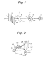
- Fig. 1 shows a conventional multi-slit projector for irradiating a plurality of parallel lights.
- a light from a high-brightness lamp 11 such as a xenon lamp is incident upon a lens 13 through slits 12 which produce a plurality of slit lights 14 irradiating an object to be measured.
- the slits 12 and lens 13 are selected so as to be capable of obtaining a desired length L1 of the slit lights 14.
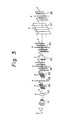
- Fig. 2 shows another conventional example in which, through a combination of a semiconductor laser, a collimating lens, a cylindrical lens, etc., a plurality of light sources 21, 22, and 23 for irradiating slit lights on a mirror 25 are arranged on circumferentially around the rotational shaft of a motor 24, and the mirror 25 is rotated by the motor 24 to irradiate the slit lights onto the object to be measured. Additional light sources may be arranged.
- the length L2 of the mirror 25 is, for example, 12 cm, and the distance between the rotational shaft of the motor 24 and the light sources 21, 22, 23 is set, for example, to 20cm, thus leading to a comparatively large-sized configuration.
- the multi-slit projector in the three-dimensional measuring apparatus has a constitution as shown in Fig. 3, in which laser lights having a single wavelength emitted from a semiconductor laser 31 are focused to produce parallel lights, which are incident on a first diffraction grating 34 which produces an output light 38 consisting of spot lights arranged in the y-axis direction, which in turn strikes on a second diffraction grating 35.
- the diffraction grating 35 is formed so that its diffractive direction is perpendicular to that of the first diffraction grating 34, and thus the spot lights are made output lights arranged in a plurality lines and which fall on a cylindrical lens 33.
- the first and second diffraction gratings 34, 35 may be constituted of optical fibers having a diameter of, for example, about 20 to 70 ⁇ m, and arranged in a plane.
- the cylindrical lens 33 is extended in the x-axis direction, which produces an output light 40 in the form of a multi-slit light consisting of spot lights linked in the y-axis.
- the output light 40 is a multi-slit light consisting of spot lights linked in the x-direction.
- the output light 40 arrives at the shutter array 37, which produces a coded multi-slit light pattern 36 by a selective opening and closing of the shutter array.
- the shutter array 37 may be constituted, for example, by liquid crystal shutters utilizing a polarization effect, or shutters utilizing electrooptical effect elements.
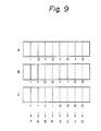
- Fig. 9 is an explanatory drawing of the conventional coded multi-slit light pattern, in which different patterns A, B, and C are projected in sequence to produce patterns of eight slit lights.
- the pattern A has an alternate slit light pattern
- the pattern B has an alternate pair of slits light pattern
- the pattern C has an alternate adjacent four slits light pattern, and Each time these three kinds of coded multi-slit light pattern are projected, picked-up image signals are stored in the image memory.
- the slit light is the No. 5 slit light.
- "n" kinds of multi-slit light patterns are projected for 2 n slit lights, all of the slit numbers can be recognized. In this manner, since respective numbers of the multi-slit lights projected on the object to be measured are identified, the position of each point of the object to be measured can be three-dimensionally calculated, to thereby determine the three-dimensional configuration thereof.
- the measurement In the three-dimensional measuring means using the slit lights, the measurement must have an accuracy equal or superior to that of the pixel resolution of the imaging apparatus.
- the width of the slit light is determined by the slit 12, which usually makes the slit light width larger than the pixel of the imaging apparatus, partially because the light source 11 does not emit parallel light and the phases of the lights are different, and thus an image of light overlaps two pixels of the imaging apparatus, and accordingly, it is difficult to improve the resolution.
- slit lights are projected onto the object to be measured, and picked up on a two-dimensional plane in the form of coordinates, to measure the distance from an observation point, and thus a drawback arises in that the measuring time is prolonged due to the necessity for a successive scanning.
- the conventional examples shown in Fig. 2 have a brightness distribution of the slit lights in the sectional direction in the form of a Gaussian distribution. Accordingly, even though the slit light image overlaps two pixels, the center of the slit light can be determined by a weighted operation or comparative operation, to thereby improve the pixel resolution.
- the conventional example shown in Fig. 2 must have several tens of light sources arranged circumferentially around the rotational shaft of the motor 24, which results in an enlargement of the apparatus size and a higher production cost, and thus it is difficult to put the apparatus to practical use.
- a multi-slit projector must be mounted on the moving body, which requires miniaturization.
- the conventional example as shown in Fig. 1 uses a high-brightness lamp 11, which prevents such a miniaturization. Also, as described earlier, it is difficult to miniaturize the conventional example shown in Fig. 2.
- the miniaturization of the multi-slit projector shown in Fig. 3 is easy because it employs only the single semiconductor laser 31, the first and the second diffraction gratings 34 and 35, and the cylindrical lens 33, to obtain a multi-slit light.
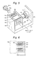
- a multi-slit projector in a three-dimensional measuring apparatus is now described with reference to Fig. 4.
- the multi-slit projector shown in Fig. 4 is based on the multi-slit projector shown in Fig. 3, but an improvement in the pixel resolution is attained by making the multi-slit lights movable.
- the multi-slit projector comprises a light source 41 for emitting parallel lights; first and second diffraction gratings 42 and 43 for receiving the parallel lights from the light source 41 and for diffracting the parallel lights in diffractive directions perpendicularly to each other; a cylindrical lens 44 on which output lights diffracted by the first and second diffraction gratings 42 and 43 are incident and which produces a plurality of parallel slit lights dispersed in the diffractive direction of either one of the first and second diffraction gratings 42 and 43; and a shutter array for obstructing predetermined slit lights among the parallel slit lights from the cylindrical lens 44, to thereby form a code therefrom.
- an actuator 46 for displacing a configuration including at least one of the first and second diffraction gratings 42 and 43 by only a minute distance in the direction perpendicular to the parallel slit lights.
- the cylindrical lens 44 produces parallel slit lights arranged in the direction perpendicular to the longitudinal direction of the cylindrical lens 44 and having a pitch 10, which impinges on the shutter array 5 by which the parallel slit lights are formed into a code by a selective use of the shutters.
- the parallel slit lights 49 are the same as when slit lights having a pitch equal to half of the pitch P are irradiated, thereby improving the pixel resolution.
- the parallel slit lights 49 are the same as when the slit lights have a 1/3 pitch of the pitch P. Namely, the pixel resolution can be improved by a simple structure.
- FIG. 5 is a perspective view of the multi-slit projector according to an embodiment of the present invention, in which a voice coil motor 60 is used as an actuator
- Fig. 6 is a sectional view of the principal part thereof.
- reference numeral 51a denotes a semiconductor laser
- 51b a collimating lens
- 52 a first diffraction grating
- 53 a second diffraction grating
- 54 a cylindrical lens
- 55 a shutter array
- 56 a support frame for supporting the first and second diffraction gratings 52 and 53, the cylindrical lens 54, and the shutter array 55
- Reference numeral 57 represents a base plate
- 57a is an upright portion thereof
- 58 and 59 are support springs
- 61 is an iron core
- 62 is a coil
- 63 is a support cylinder
- 64 designates a permanent field magnet.
- a light having a single wavelength emitted from the semiconductor laser 51a is converted into a parallel beam by the collimating lens 51b and arrives at the first diffraction grating 52 which produces an output light consisting of oval spot lights arranged in a line.
- the output light falls on the second diffraction grating, which produces spot lights arranged in a matrix, and impinges on the cylindrical lens 54.
- the cylindrical lens 54 is in the shape of a half-cylinder, but also may have a fully cylindrical shape.
- the spot lights are arranged in the direction perpendicular to the longitudinal direction of the cylindrical lens 54, as chain-like slit lights respectively through the cylindrical lens 54, and arrive at the shutter array 55.
- the shutter array 55 When the shutter array 55 is completely opened, all of the slit lights are output in the form of a multi-slit light. Further, when the multi-slit light is irradiated a plurality of times, it can be coded by closing the shutters at selected locations.
- the shutter array 55 for example, a liquid crystal shutter array utilizing a polarized light, and a shutter array having electrooptic effect elements intervened between the polarizing plates can be used.
- electrodes can be selected to apply voltage, to thereby control the opening and closing of the selected shutter.
- the iron core 61 is fixed to the upright portion 57a of the base plate 57, and facing the permanent field magnet 64 fastened to the iron core 61 is the coil 62 secured to the support cylinder 63, which in turn is connected to the support spring 59.
- the bottom ends of the support springs 58 and 59 respectively are fixed to the base plate 57, and at the top ends thereof, there is mounted a support frame to which is fixed the first and second diffraction gratings 52 and 53, the cylindrical lens 54, and the shutter array 55.
- the support cylinder 63 fixing the coil 62 is displaced by a magnetic attraction or repulsion produced between the coil 62 and the permanent field magnet 64, which causes the configuration including the first and the second diffraction gratings to shift by a minute distance with respect to the light source, against the support springs 58 and 59.
- the multi-slit light is composed of longitudinal slit lights, a laterally microscopic displacement thereof occurs.
- the minute displacement is, for example, half a pitch P of the multi-slit light
- the situation is the same as when the multi-slit light having a P/2 pitch is irradiated onto the object to be measured. It is also possible to displace same at a pitch of P/3 or P/4, and such a microscopic displacement can be accurately achieved without difficulty by a feedback control of the voice coil motor 60.
- a continuous displacement between the slit lights also can be used for the measurement of the object.
- the configuration including at least one of the first and the second diffraction gratings is shifted by only a minute distance, so that positional slippage between the multi-slit light and the shutter should be taken into consideration when the shutter array 55 is fixed.
- the first and second gratings can be constituted of an optical fiber array.
- the first diffraction grating 42 consists of a plurality of optical fibers extending along the X-axis and arranged in the Y-axis direction
- the second diffraction grating 43 consists of Y-axis extending optical fibers arranged in the X-axis direction.
- adjacent slit lights have an irradiation angle ⁇ ⁇ established by the following expression; where ⁇ is a wavelength of the light emitted from the semiconductor laser 51a, "d” is a diameter of the optical fiber constituting the first and second diffraction gratings 12 and 13, ⁇ m is an angle between the slit lights respectively having a diffraction mode 0 (a slit light emitted on the optical axis) and having a diffraction mode "m” (a "m”th slit light from the optical axis), and ⁇ m-1 represents an angle between the slit lights of mode 0 and mode "m-1".
- the interval W m between slit lights projected on the object spaced by a distance L is given by the following expression.
- the distance by which the support springs 58 and 59 are displaced by the voice coil motor 60 may be 20 to 100 ⁇ m or less.
- slit lights can be projected by displacing at least one of the first and second diffraction gratings 52 and 53 by a microscopic distance, thereby improving the pixel resolution.
- Fig. 7 is a perspective view of a multi-slit projector according to another embodiment of the present invention, in which a piezoelectric element 65 is used as the actuator.
- a piezoelectric element 65 is used as the actuator.
- the same elements are designated by the same reference numerals.
- the piezoelectric element 65 in this embodiment providing a desired displacement is not obtained by a single piezoelectric element, and a plurality of piezoelectric elements may be stacked to cause a displacement on the order of 20 to 100 ⁇ m, without difficulty.
- an accurate microscopic displacement can be ensured under a feedback control.
- a configuration including at least one of the first and second diffraction gratings 52 and 53 can be displaced by only a minute distance, by the support springs 58 and 59 through the support frame 56.
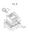
- Fig. 8 is a perspective view of a multi-slit projector according to further embodiment of the present invention, in which a linear motor 66 is used as the actuator.
- a linear motor 66 is used as the actuator.
- the same elements are labelled with the same reference numerals.
- the linear motor 66 in accordance with this embodiment comprises a moving element 67 to which the support frame 56 is fixed, a stator 68, and wheels 69 and a guide rails 70 which guide the moving element 67.
- a coil is mounted on either the moving element 67 or the stator 68, and a permanent magnet is mounted on the other.
- the moving element 67 is guided by the wheels 69 and the guide rails 70 to be shifted by a minute distance.
- a desired amount of minute displacement can be accurately achieved by a position sensing and a feedback control.
- the configuration including at least one of the first and second diffraction gratings 52 and 53 is fixed to the support frame 56 so as to allow a minute displacement by the moving element 67.
- the present invention is not restricted to the above described embodiments.
- various arrangements can be employed besides the voice coil motor 60, the piezoelectric element 65, or the linear motor 66.
- the multi-slit projector comprises the first and second diffraction gratings 42 and 43, the cylindrical lens 44, and the shutter array 45, in which parallel lights from the light source 41 are made a multi-slit light, and a configuration including at least one of the first and second diffraction gratings 42 and 43 is displaced by only a minute distance with respect to the light source by the actuator 46, to allow the slit lights to be irradiated on spaces between the slit lights, and accordingly, can be controlled such that a situation identical to the situation in which the pitches between the slit lights can be even lessened or the space between the slit lights can be successively scanned, to thereby improve the pixel resolution and accomplish the miniaturization of the apparatus without difficulty.
- the present invention can be applied to the multi-slit projector for three-dimensional measurement which realizes a visual function and the like for a robot or other various automatic apparatuses. Further, an accuracy of the three-dimensional measurement for the object to be measured can be improved by simple structure.
- the image signals corresponding to the coded multi-slit light patterns are stored in the image memories respectively, and then are collated to decode the coded multi-slit light, i.e., to number the slit lights. Therefore, this has a disadvantage that many image memories must be provided.
- the decoding of the coded multi-slit lights is carried out by collating data in the corresponding image memory after projecting all of the patterns, and therefore a drawback arises in that the processing time is prolonged and the number of patterns increased as a result of an increase of the number of multi-slit lights.
- the image recognizing device in the three-dimensional measuring apparatus is intended to speed-up the processing and to reduce the memory capacity by the application of the image processing described with reference to Fig. 10.
- the three-dimensional measuring apparatus in Fig. 10 comprises a multi-slit projector 101 for projecting a multi-slit light pattern under the control of a shutter array, and a picked-up image recognizing device 108.
- the picked-up image recognizing device 108 comprises an image pick up unit 102 for picking up the coded multi-slit light pattern projected on an object to be measured, a binarization circuit 3 for binarizing the image signals from the image pick up unit 102, an image arithmetic unit 105 which changes a weight assigned to the binarized image signal, which is converted by the binarization circuit 103 each time the coded multi-slit light pattern is changed, and sums up the last weighted binarized image signals or the image signals of the last addition results read out from the image memory 104, and the newly weighted binarized image signals, a coded pattern irradiated point memory 106 for storing the coordinates for the coded pattern irradiated points of the object to be measured corresponding to the multi-s
- the multi-slit projector 101 and the image pick up unit 102 are arranged on a surface which crosses each of the multi-slit lights at a right angle, and are arranged to have the same X axis extending parallel to the direction of the array of the multi-slit lights.
- the distance calculating unit 107 is constructed by a read-only memory (ROM) which can read out the data of the three-dimensional position by the use of the coordinates of the coded pattern irradiated points stored in the coded pattern irradiated point memory 106 as the addresses.
- ROM read-only memory
- the multi-slit projector 101 comprises, as described with reference to Fig. 3 or Fig. 4, a semiconductor laser, first and second diffraction gratings, a cylindrical lens, and a shutter array which projects a coded multi-slit light pattern.
- the image pick up unit 102 is a television camera which picks up an image of an object to be measured,which is subjected to a multi-slit light, and the image signals are binarized by the binarization circuit 103. Note, alternatively, after storing the image signals in the image memory 104, they may be binarized by the binarization circuit 103.
- the image calculating unit 105 changes a weight assigned to a binarized image signal each time the coded multi-slit light pattern is changed, and sums up the last weighted binarized image signal and newly weighted binarized image signal, or sums up the content in the image memory 104 storing the last addition results and newly weighted binarized image signal.
- the first binarized image signal in the coded multi-slit light pattern is assigned a weight 20 and is stored in the image memory 104
- the second binarized image signal is assigned a weight 21.
- the first and the second binarized image signals with the weights are then added and stored in the image memory 104, a weight 22 is assigned to a third binarized image signal, and the third binarized signal with the weight 22 and the previously added result are added and stored in the image memory 104.
- the coordinates of the coded pattern irradiated points of the object to be measured determined by projecting the multi-slit light are stored in the coded pattern irradiated point memory 106, and based on the coordinates of the coded pattern irradiated points, the three-dimensional position is determined by the distance calculating unit 107. Namely, the coordinates position of the coded pattern irradiated points are calculated by a triangulation.
- the multi-slit projector 101 and the image pick up unit 102 are arranged on a surface which crosses each of the multi-slit lights at a right angle, and by arranging them to have the same X axis extending parallel to the direction of the array of the multi-slit lights, it becomes possible to previously determine the coefficients in the distance calculation, thereby making it possible to use the read-only memory (ROM) to read out the three-dimensional position of the object to be measured from the coordinates stored in the coded pattern irradiated memory 106.
- ROM read-only memory
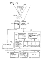
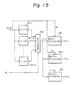
- Fig. 11 is a block diagram showing the embodiment of Fig. 10 in more detail.
- a reference numeral 110 denotes an image processor, 111 a multi-slit projector, 112 an image pickup unit, 113 a binarization circuit, 114 an image memory consisting of regions M1 to M4 each having a capacity for one screen of, for example, 8 bits for each pixel, 115 an image arithmetic unit, 116 a coded pattern irradiated point memory, 117 a distance calculating unit, 118 a processor (CPU) for controlling each unit, 119 a main memory, 120 an interface unit, 121 a common bus, 122 a multi-slit light, and 123 an object to be measured.
- CPU processor
- the multi-slit projector 111 is the same as that shown in Fig. 4 or Fig. 5.
- the image pick up unit 112 picks up the multi-slit lights 122 projected onto the object 123 to be measured, and the pick up image signal is binarized by the binarization circuit 113, and then applied to the image arithmetic unit 115 or the image memory 114.
- the pick up image signal may be stored in the image memory 114, and then binarized by the binarization circuit 113.
- the image processor 110 includes the binarization circuit 113, the image memory 114, the image arithmetic unit 115, and a coded pattern irradiated point memory 116.
- the binarized image signal is weighted by the binarization circuit 113 or the image arithmetic unit 115, and control data for projecting a coded multi-slit light pattern from the multi-slit projector 111 are transferred from the processor 118 to the image processor 110. The weighting is controlled based on the transferred control data.
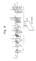
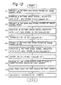
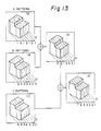
- Fig. 12 is a flowchart explaining the operation of the three-dimensional measuring apparatus shown in Fig. 11, which is composed of steps S1 to S11. Further, Fig. 13 is a diagram also explaining the operation of the apparatus shown in Fig. 11. In this embodiment, a multi-slit consisting of eight slit lights is projected. More slit lights are, of course, applicable if required.
- a pattern A is projected onto the object 123 to be measured, and the image signal picked up by the image pick up unit 112 is stored in the memory region M1 in the image memory 114 (S1).
- This pattern A is composed of alternate slit lights (shown by the solid line), in which the broken line designates lights obstructed by the shutter array.
- the slit lights are picked up through the image pick up unit from an angle which is different from the angle at which the multi-slit light is projected, and thus they can be picked up in a bent or curved state corresponding to the configuration of the object 123 to be measured. For example, if each slit light is picked up in the form of a line, it is proved to be a plane.
- the image signal of the pattern A stored in the memory region M1 is binarized by the binarization circuit 113, and weighted and stored in the memory region M2, which is designated as an image signal IA (S2).
- This pattern B is composed of slit lights arranged alternate pair of slits light pattern.
- the image signal stored in the memory region M3 is binarized by the binarization circuit 113, and the weighting is performed by the binarization circuit 113 or the image arithmetic unit 115.
- the image signal IA stored in the memory region M2 and the image signal IB stored in the memory region M4 are each read out, both are summed by the image arithmetic unit 115, and the result is stored in the memory region M1, which is designated as an image signal IS (S5). Consequently, as shown in Fig. 13, the image signal IS is constituted of the multi-slit light represented by a code "32103210".
- This pattern C is composed of slit lights arranged on alternate adjacent four slits light pattern.
- the weighted signal is then stored in the memory region M4 and designated as an image signal IC (S7).
- the image signal IC composed of a multi-slit light represented by a code "44 440000" is obtained.
- the image signal IS stored in the memory region M1 and the image signal IC stored in the memory region M4 are summed up with the aid of the image arithmetic unit 115, and the added result is stored in the memory region M2.
- the stored result is designated as an image signal IS' (S8).
- the image signal IS' consisting of a multi-slit light represented by a code "76543210" is obtained, and thus the coded multi-slit light is decoded.
- the coding is based on the natural binary number, but other codes such as a Gray code are also applicable.
- the image signal IS' stored in the memory region M2 and showing the decoded result is represented by the multi-number, and thus it must be binarized to store the coordinate points having a level higher than 20 to the coded pattern irradiated point memory 16 (S9). Then, the content of the coded pattern irradiated point memory 116 is read out (S10), and a distance between coordinate points is calculated by the distance calculating unit 117 (S11). In this case, the distance calculation is executed by the special purpose distance calculating unit 117, but the operation function of the processor 118 may be utilized instead. Where various parameters and the like are predetermined, it is also possible to use a read only memory (ROM) as the distance calculating unit 117.
- ROM read only memory
- the "j"th slit light produces a projection image P on the object to be measured while its pick up image I is formed on the image surface ⁇ I of the image pick up device 112.
- a three-dimensional position of a point P k (X k , Y k , Z k ) on the projection image can be calculated as follows, as an intersection point between a line of sight OI k connecting the lens center O and a point I k (x k , y k ) on the image plane.
- the coordinates (x k ,y k ) can be determined as the coordinates stored in the coded pattern irradiated point memory 116, and ⁇ j can be determined from the decoded slit light No. j. Namely, the value of "j" can be obtained as a gray level stored in the coded pattern irradiated point memory 116.
- Fig. 15 is a block diagram of the principal part of the distance calculating unit 117, in which the coordinates x k and y k read out from the coded pattern irradiated point memory 116, and the focal distance f, are input, and values u(1) to u(m) according to the above expression (3) are calculated by calculating units 151-1 to 151-m corresponding to slit light numbers (1) to (m).
- u(j) corresponding to one of the slit light numbers (1) to (m) is applied to the multiplication portions 153 to 155 with the aid of a selector 152, which executes multiplication based on the expression (2), to determine the three-dimensional positions X k , Y k and Z k .
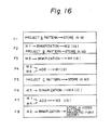
- Fig. 16 illustrates an example of the operation of a pipeline processing by the measuring apparatus shown in Fig. 11.
- F1 to F8 denote frames of the image signals, respectively.
- the pattern A is projected on the object 123 to be measured, and the image signals picked up by the image pick up unit 112 are stored in the memory region M1.
- the image signals of the pattern A in the memory region M1 are binarized, and stored in the memory region M2 as the image signals IA, and the pattern B is projected onto the object 123 to be measured, and the image signals by the image pick up unit 112 are stored in the memory region M3.
- the image signals of the pattern B in the memory region M3 are binarized, and stored in the memory region M4 as the image signals IB.
- the pattern C is projected onto the object 123 to be measured, and the image signals by the image pick up unit are stored in the memory region M3.
- the image signals of the pattern C in the memory region M3 are binarized and stored into the memory region M4 as image signals IC.
- the contents of the memory regions M1 and M4 are summed up and stored in the memory region M2 in the form of image signals IS', and thus the coded multi-slit light is decoded.
- the image signals IS' in the memory region M2 are binarized, and stored in the coded pattern irradiated point memory 116.
- the decoding in this embodiment requires seven frame periods in the case of eight slit lights. For more slit lights, however, it is possible to decode, for example, by nine frame periods in the case of 16 slit lights, and by 11 frame periods in the case of 32 slit lights. That is, the greater the number of slit light, the lower the increase in the number of additional frames.
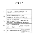
- Fig. 17 illustrates another example of the operation of a pipeline processing in the apparatus shown in Fig. 11.
- the pattern A is projected, and the image signals by the image pick up unit 112 are stored in the memory region M1.
- image signals having the pattern A in the memory region M1 are binarized and stored in the memory region M2 as the image signals IA, and the pattern B is projected onto the object 123 to be measured, and the image signals by the image pick up unit 112 are stored in the memory region M3.
- the procedures are the same as those in the embodiment shown in Fig. 16.
- the 16 are simultaneously executed, i.e., the pattern C is projected onto the object 123 to be measured, the image signals picked up by the image pick up unit 112 are stored in the memory region M4, the pattern B image signals in the memory region M3 are binarized, and the image signals IA in the memory region M2 are read out, delayed corresponding to the binarization processing to perform the addition, and stored in the memory region M1 as the image signals IS.
- the processes in the frames F6 and F7 are simultaneously conducted, that is, the image signals of the pattern C in the memory region M4 are binarized, the image signals IS are read out, delayed corresponding to the binarization processing to perform the addition, and stored in the memory region M2 as the image signals IS', and thus the coded multi-slit light is decoded.
- the image signals IS' are binarized, and stored in the coded pattern irradiated point memory 116. Note, on the frame F5, a step for projecting the pattern A for the measurement of the next object to be measured may be initiated.
- the image signals read out from the memory regions M2 and M1 in the above-mentioned frames F3 and F4 commonly provide address signals for the memory regions M1 to M4, which causes a delay in the binarization processing. It is also possible to delay the read-out addresses of the image signals IA and IS, to thereby perform the addition processing between the binarized image signals.
- the binarization of the image signals, addition processing between the images, and the projection of the coded multi-slit light may be simultaneously executed, whereby the decoding is accomplished by four frames in the case of eight slit lights as described earlier, by five frames in the case of sixteen slit lights, and by six frames in the case of thirty two slit lights. Namely, even less time is required for decoding, compared to the embodiment shown in Fig. 16.
- a coded multi-slit light is projected onto the object to be measured from the multi-slit projector, the image signals picked up by the image pick up unit are binarized through the binarization circuit, each time the pattern of the coded multi-slit light is changed the weighting of the binarized image signal is altered, and the last binarized image signals or image signals of the last addition results are summed up by the image operating unit, to decode the coded multi-slit light, whereby even though the number of slit lights of the multi-slit light is large, the capacity of the image memory may be, for example, on the order of 4 screens, which results in a miniaturization and cost saving.
- an addition between the images may be executed through the image processor or the like, to thereby realize a high-speed decoding of the coded multi-slit light, thus leading to the speeding-up of the three-dimensional measurement processing.
- the multi-slit projector and the image pick up unit are arranged on a surface which crosses each of the multi-slit lights at a right angle, and are arranged to have the same X axis extending parallel to the direction of the array of the multi-slit lights, whereby it is possible to predetermine the coefficients and the like in the distance computation, and thus the read-only memory can be used to read out the three-dimensional coordinates, to consequently simplify the structure and obtaine a high-speed processing.
- the coded multi-slit light patterns "n" kinds of patterns are provided for 2 n multi-slit lights, to thereby number all of the slit lights.
- the image of the the object to be measured is obtained by the image pick up unit such as a television camera every time the "n" kinds of coded multi-slit light patterns are changed over for projection, the image signals for one screen having a plural-bit configuration for one pixel are stored in the image memories, the image signals each stored in the "n” image memories are read-out, and the slit lights are numbered by an arithmetic process between the image signals for each slit light.
- the coded multi-slit light pattern is projected on the object to be measured, picked up image signals are converted into, for example, digital signals having an 8-bit configuration for one pixel to be stored into image memories, and the image signals are stored into different image memories at every change of the coded multi-slit light pattern, and accordingly, the use of a multiplicity of slit lights leads to an increase in the number of patterns, which requires a multiplicity of image memories, thus resulting in increased production costs. Further, based on the image signals stored in each image memory, the collating processing and the like are successively performed by a slit light, thereby increasing the number of slit lights, and thus prolonging the processing time.
- the three dimensional measuring apparatus aims to speed up the three-dimensional measurement by a parallel processing, the principle of which will be described with reference to Fig. 18.
- the measuring apparatus comprises a multi-slit projector 181 for projecting coded multi-slit light patterns onto an object to be measured, an image pick up unit 182 consisting of a television camera or the like and for obtaining an image of the coded multi-slit light patterns projected onto the object to be measured, a binarization circuit 183 for binarizing image signals from the image pick up unit 182, a plurality of image memories 184-1 to 184-n for storing binary image signals from the binarization circuit 183 so as to correspond with the coded multi-slit light patterns, an address generation circuit 185 for generating address signals for the plurality of image memories 184-1 to 184-n, and a distance calculation unit 186 which determines three dimensional positions of coded pattern irradiated points of the object to be measured, based on the address signals from the address generation circuit 185 and a slit light number having a bit configuration composed of the binary image signals simultaneously read-out from the plurality of image
- the measuring apparatus further comprises a decision control circuit which forms slit light numbers having a bit configuration excluding all "0"s from the bit configuration of the binary image signal simultaneously read out from the plurality of image memories 184-1 to 184-n, and only with respect to the slit light number, applies address signals from the address generation circuit 185 to the distance calculation unit 186.
- the measuring apparatus comprises the multi-slit projector 181 for projecting coded multi-slit light patterns onto an object to be measured, the image pick up unit 182 including a plurality of light receiving elements and for picking up the coded multi-slit light patterns projected onto the object to be measured, the binarization circuit 183 corresponding to the light receiving elements and for binarizing each of outputs of the image pick up unit 182, shift registers corresponding to the light receiving elements and for shifting to store the output signals of the binarization circuit corresponding to the light receiving elements each time the coded multi-slit light patterns are changed over, the shift registers being a serial-in /parallel-out type, an address generation circuit which produces address signals for specifying the shift registers corresponding to the light receiving elements, and a distance calculation unit which determines a three-dimensional position of coded pattern irradiated points of the object to be measured, based on the address signals from the address generation circuit, and a slit light number having a bit configuration read
- multi-slit light patterns are projected onto the object to be measured, by the multi-slit projector 181, and the image signals obtained by picking up the object to be measured through the image pick up unit 182 are binarized by the binarization circuit 183 and are stored in the image memories 184-1 to 184-n corresponding to coded multi-slit light patterns.
- the binary image signals obtained by successively projecting "n" kinds of coded multi-slit light patterns are stored in "n” image memories 184-1 to 184-n.
- the binary image signals are simultaneously read out from the "n" image memories 184-1 to 184-n in compliance with the address signals from the address generation circuit 185, and accordingly, n-bit signals are obtained and assigned weights of 20 to 2 n-1 , respectively, to be decoded and thus obtain slit light numbers.
- the distance from the observation point to the object to be measured can be calculated in the distance calculation unit 186, to thus obtain a three-dimensional position of the object to be measured.
- the binary image signals between slit lights of the coded multi-slit light pattern become "0", and when the binary image signals simultaneously read-out from the image memories 184-1 to 184-n are all "0", the address signals are not allowed to be used for the distance calculation. Therefore, this is determined in the decision control circuit, to prevent an input of useless address signals to the distance calculating unit 186.
- the image pick up unit 182 is constituted of a plurality of light receiving elements arranged two-dimensionally, and the binarization circuit consisting of comparators and the like is provided, in which the binarized signals are input to the shift registers and shifted each time the coded multi-slit light patterns are changed.
- the binarization circuit consisting of comparators and the like is provided, in which the binarized signals are input to the shift registers and shifted each time the coded multi-slit light patterns are changed.
- binary image signals for each coded multi-slit light pattern by one pixel are stored in each shift register.
- the address generation circuit generates address signals specifying the shift register by one picture element, and the plurality of bits is read-out in parallel from the shift register specified by the address signals, to be decoded and thus determine the slit light numbers. Based on the slit light numbers and the address signals, a three-dimensional position of the object to be measured can be obtained.
- Fig. 19 is a block diagram of an embodiment of the present invention, in which reference numeral 190 denotes an object to be measured, 191 a multi-slit projector, 192 a television camera constituting an image pick up unit, 193 a binarization circuit, 194-1 to 194-3 image memories corresponding to coded multi-slit light patterns, 195 an address generation circuit, 196 a distance calculation unit, 197 a table for storing effective data, 198 a decision control circuit, and 199 represent a projection control unit.
- reference numeral 190 denotes an object to be measured
- 191 a multi-slit projector
- 192 a television camera constituting an image pick up unit
- 193 a binarization circuit
- 194-1 to 194-3 image memories corresponding to coded multi-slit light patterns 195 an address generation circuit
- 196 a distance calculation unit
- 197 a table for storing effective data
- 198 a decision control circuit a decision control circuit
- 199 represent a
- This embodiment shows a case where three kinds of coded multi-slit light patterns are sequentially projected onto an object to be measured through the multi-slit projector 191, and three image memories 194-1 to 194-3 are provided corresponding to coded multi-slit light patterns. Further, an image of the object 190, to be measured on which coded multi-slit light patterns are projected, is obtained by the television camera 192, the obtained image signals are binarized by the binarization circuit 193, and the binary image signals "c" are stored in the memory 194-1 to 194-3.
- Switching signals "a” for the coded multi-slit light patterns derived from the projection control unit 199, and address signals “b” from the address generation circuit 195 are stored in the three image memories 194-1 to 194-3.
- the switching signals "a” specify the image memory 194-1 when the first coded multi-slit light pattern is projected, the image memory 194-2 when the second coded multi-slit light pattern is projected, and the image memory 194-3 when projecting the third coded multi-slit light pattern. Then binary image signals corresponding to pixels are stored into the addresses specified by the address signals "b".
- a read-out is simultaneously carried out by using the address signals "b" from the address generation circuit 195.
- the read-out signals d1, d2, and d3 are applied to the decision control circuit 198.
- a slit light number L in the coordinates x, y is obtained by the address signals "b".
- a solid line signifies the presence of the multi-slit light and a broken line represents the absence of the multi-slit light.
- the binary image signals obtained when the coded multi-slit light pattern A is projected are stored in the image memory 194-1
- the binary image signals obtained when projecting the coded multi-slit light pattern B are stored in the image memory 194-2
- the binary image signals obtained through the projection of the coded multi-slit light pattern C are stored in the image memory 194-3.
- the decision control circuit 198 is designed to write only address signals "b", by which slit light numbers can be determined, into the table 197 by writing signals "e”, which makes a more effective use of the table 197. Namely, the binary image signals corresponding to pixels between a slit light and the next slit light are not subjected to the projection of slit lights even though the coded multi-slit light pattern is changed over, which produces all "0s”. When all "0s" are discriminated, the address signal "b" can not be written into the table 197.
- the distance can be calculated as follows. Namely, in Fig. 14 again, O-XYZ signifies a coordinates system having the center of the lens of the television camera 192 as its origin, and o-xyz represents a light source coordinates system having the center of the light source of the multi-slit projector 191 as its origin.
- a three-dimensional position of a point P k (X k ,Y k Z k ) on the projection image can be calculated as follows, as an intersection point between a line of sight O-I k connecting the lens center O and a point I k (x k , y k ) on the image plane ⁇ I , and the slit light plane where (x k ,y k ) signifies the position of the P k on the image plane, ⁇ j represents a projection angle of the slit light plane, and "f" means a focal distance. determined from the slit light number
- the position (x k , y k ) of the point I k on the image plane ⁇ j corresponds to the addresses in the image memories 194-1 to 194-3.
- the projecting angle ⁇ j can be determined by the slit light number j.
- the slit light number can be determined by the 3-bit configuration of signals d1 to d3 read out in accordance with the address signals " b" from the image memories 194-1 to 194-3, so that the address signals and the slit light number L, which are both indispensable for the distance calculation, can be determined by changing over the predetermined kinds of coded multi-slit light patterns sequentially for the projection, without the need to calculate for the image signals, and as a result, a high-speed three-dimensional measurement can be obtained.
- the image memories 194-1 to 194-3 Although the number of the image memories 194-1 to 194-3 must be increased depending on the number of the coded multi-slit light patterns, the image memories store the binary image signals so that the capacity is not enormous overall, which facilitates the speeding-up of the processing of number of slit lights necessary for the distance calculation.
- the table 197 and the decision control circuit 198 may be omitted.
- signals d1 to d3 are read out simultaneously from the image memories 194-1 to 194-3, and the address signals "b" are applied to the distance calculation unit 196 in which the slit light number is determined, to thereby perform the distance calculation for the three-dimensional position X, Y, Z of the coded pattern irradiated point for the object 190 to be measured.
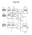
- Fig. 20 is a block diagram of another embodiment of the present invention, in which reference numerals 201-1 through 201-m denote light receiving elements such as photo-diodes arranged two-dimensionally, 202-1 through 202-m signify binarization circuits corresponding to the light receiving elements, 203-1 through 203-m are serial-in / parallel-out shift registers corresponding to the light receiving elements, 34 stands for an address generator, 35 a bus, and 36 represents a distance calculation unit.
- reference numerals 201-1 through 201-m denote light receiving elements such as photo-diodes arranged two-dimensionally
- 202-1 through 202-m signify binarization circuits corresponding to the light receiving elements
- 203-1 through 203-m are serial-in / parallel-out shift registers corresponding to the light receiving elements
- 34 stands for an address generator
- 35 a bus
- 36 represents a distance calculation unit.
- a multi-slit light pattern is projected onto an object to be measured (not shown in Fig. 20), the projection image is picked up by the image pick up unit composed of the light receiving elements 201-1 through 201-m, whose output signals are applied to the binarization circuits 202-1 through 202-m, respectively.
- These binarization circuits 202-1 through 202-m may be constituted of comparator which compares the signals from the light receiving elements 201-1 to 201-m with a reference voltage "r".
- the binary image signals from the binarization circuits 202-1 through 202-m are applied to the the shift registers 203-1 through 203-m, and then shifted by a shift signal "s".
- the shift signal "s" is applied at the time of the change-over of the coded multi-slit light pattern.
- the shift registers 203-1 to 203- m may each comprise three stages. Namely, the binary image signals for three screens can be stored by all of the shift registers 203-1 to 203-m.
- Address signals x, y are applied to the shift registers 203-1 to 203-m and the distance calculation unit 36 from the address generation circuit 234.
- one of the shift registers 203-1 to 203-m is specified by the address signals x, y derived from the address generation circuit 204, and the signals read out in parallel are applied to the distance calculation unit 206 through the bus 205.
- the three-kinds of coded multi-slit light patterns are used as described before, three bits are read out in parallel from the shift register specified by the address signals x, y, with the result that the slit light number L can be determined in the same manner as with the three bits of d1 to d3 in the above described embodiments. Namely, by using the address signals x, y and the slit light number L, the three-dimensional position X, Y, Z of a coded pattern irradiated point of the object to be measured can be determined.
- the three-dimensional measuring apparatus as a whole can be mounted within a camera as a one body. Further, by the provision of the integrated circuit further including the shift registers 203-1 to 203-m, the number of light receiving elements 201-1 to 201-m is increased, to thus improve the resolution.
- coded multi-slit light patterns are projected onto the object to be measured, an image of which is obtained by the image pick up unit, binarized, and stored into the image memories corresponding to the coded multi-slit light patterns.
- the stored image data are read out simultaneously in accordance with the address signals.
- the read out signals having a plural-bit configuration are decoded to immediately determine the slit light number, and thus the slit light number and concurrent address signals can be used for the distance measurement. Namely, without a particular increase of the capacity of the memories, a speeding up of the three-dimensional measurement can be accomplished.
- the image pick up unit is constituted of the two-dimensionally arranged light receiving elements 201-1 to 201 -m, and the binarization circuits 202-1 to 202-m and the shift register 203-1 to 203-m are provided correspondingly to the light receiving elements, in which the coded multi-slit light patterns are changed over so as to be projected onto the object to be measured, and the binary image signals are stored in the shift registers, and are read out from the shift register specified by the address signals, to thus determine the slit light number.
Priority Applications (2)
| Application Number | Priority Date | Filing Date | Title |
|---|---|---|---|
| EP99122065A EP0985903B1 (fr) | 1990-06-19 | 1991-06-19 | Appareil de mesure tridimensionelle |
| EP95103248A EP0660079B1 (fr) | 1990-06-19 | 1991-06-19 | Appareil de mesure de trois dimensions |
Applications Claiming Priority (6)
| Application Number | Priority Date | Filing Date | Title |
|---|---|---|---|
| JP15879990A JPH0451112A (ja) | 1990-06-19 | 1990-06-19 | マルチスリット投光器 |
| JP158799/90 | 1990-06-19 | ||
| JP165560/90 | 1990-06-26 | ||
| JP2165560A JPH0820232B2 (ja) | 1990-06-26 | 1990-06-26 | 三次元計測装置 |
| JP277660/90 | 1990-10-18 | ||
| JP27766090A JP2864163B2 (ja) | 1990-10-18 | 1990-10-18 | 三次元計測装置 |
Related Child Applications (2)
| Application Number | Title | Priority Date | Filing Date |
|---|---|---|---|
| EP95103248.1 Division-Into | 1991-06-19 | ||
| EP95103248A Division EP0660079B1 (fr) | 1990-06-19 | 1991-06-19 | Appareil de mesure de trois dimensions |
Publications (2)
| Publication Number | Publication Date |
|---|---|
| EP0462595A2 true EP0462595A2 (fr) | 1991-12-27 |
| EP0462595A3 EP0462595A3 (en) | 1992-09-02 |
Family
ID=27321410
Family Applications (3)
| Application Number | Title | Priority Date | Filing Date |
|---|---|---|---|
| EP19910110071 Ceased EP0462595A3 (en) | 1990-06-19 | 1991-06-19 | Three-dimensional measuring apparatus |
| EP99122065A Expired - Lifetime EP0985903B1 (fr) | 1990-06-19 | 1991-06-19 | Appareil de mesure tridimensionelle |
| EP95103248A Expired - Lifetime EP0660079B1 (fr) | 1990-06-19 | 1991-06-19 | Appareil de mesure de trois dimensions |
Family Applications After (2)
| Application Number | Title | Priority Date | Filing Date |
|---|---|---|---|
| EP99122065A Expired - Lifetime EP0985903B1 (fr) | 1990-06-19 | 1991-06-19 | Appareil de mesure tridimensionelle |
| EP95103248A Expired - Lifetime EP0660079B1 (fr) | 1990-06-19 | 1991-06-19 | Appareil de mesure de trois dimensions |
Country Status (4)
| Country | Link |
|---|---|
| US (2) | US5307153A (fr) |
| EP (3) | EP0462595A3 (fr) |
| CA (1) | CA2044820C (fr) |
| DE (2) | DE69132853T2 (fr) |
Cited By (4)
| Publication number | Priority date | Publication date | Assignee | Title |
|---|---|---|---|---|
| WO1994004942A1 (fr) * | 1992-08-11 | 1994-03-03 | National Research Council Of Canada | Validation du mesurage telemetrique optique d'une surface cible dans un environnement encombre |
| EP0642034A1 (fr) * | 1993-09-06 | 1995-03-08 | Sony Corporation | Méthode et appareil de mesure de distance |
| US5408324A (en) * | 1992-03-19 | 1995-04-18 | Sony Corporation | Distance measuring method and apparatus that compares signals from plural photocells |
| EP2918968A3 (fr) * | 2014-03-13 | 2015-12-23 | Canon Kabushiki Kaisha | Appareil de mesure et procédé de fabrication d'article |
Families Citing this family (68)
| Publication number | Priority date | Publication date | Assignee | Title |
|---|---|---|---|---|
| JP2767340B2 (ja) * | 1991-12-26 | 1998-06-18 | ファナック株式会社 | 物体の3次元位置・姿勢計測方式 |
| US5867604A (en) * | 1995-08-03 | 1999-02-02 | Ben-Levy; Meir | Imaging measurement system |
| DE29515738U1 (de) * | 1995-10-04 | 1995-11-30 | Vosseler Hans Guenther | Meßvorrichtung zur kontaktlosen Meßanalyse von Körpern oder Oberflächen |
| US6044170A (en) * | 1996-03-21 | 2000-03-28 | Real-Time Geometry Corporation | System and method for rapid shape digitizing and adaptive mesh generation |
| US5870220A (en) * | 1996-07-12 | 1999-02-09 | Real-Time Geometry Corporation | Portable 3-D scanning system and method for rapid shape digitizing and adaptive mesh generation |
| US6549288B1 (en) | 1998-05-14 | 2003-04-15 | Viewpoint Corp. | Structured-light, triangulation-based three-dimensional digitizer |
| US6731390B2 (en) * | 1999-07-01 | 2004-05-04 | Carl Zeiss Jena Gmbh | Process and apparatus for determining surface information using a projected structure with a periodically changing brightness curve |
| US7065242B2 (en) * | 2000-03-28 | 2006-06-20 | Viewpoint Corporation | System and method of three-dimensional image capture and modeling |
| US6754370B1 (en) * | 2000-08-14 | 2004-06-22 | The Board Of Trustees Of The Leland Stanford Junior University | Real-time structured light range scanning of moving scenes |
| US6618123B2 (en) * | 2000-10-20 | 2003-09-09 | Matsushita Electric Industrial Co., Ltd. | Range-finder, three-dimensional measuring method and light source apparatus |
| US8958654B1 (en) * | 2001-04-25 | 2015-02-17 | Lockheed Martin Corporation | Method and apparatus for enhancing three-dimensional imagery data |
| DE10143504A1 (de) | 2001-09-05 | 2003-03-20 | Sick Ag | Überwachungsverfahren und optoelektronischer Sensor |
| AU2002361572A1 (en) * | 2001-10-19 | 2003-04-28 | University Of North Carolina At Chape Hill | Methods and systems for dynamic virtual convergence and head mountable display |
| US7385708B2 (en) * | 2002-06-07 | 2008-06-10 | The University Of North Carolina At Chapel Hill | Methods and systems for laser based real-time structured light depth extraction |
| JP2004037317A (ja) * | 2002-07-04 | 2004-02-05 | Murata Mfg Co Ltd | 三次元形状測定方法、三次元形状測定装置 |
| DE10304111B4 (de) * | 2003-01-31 | 2011-04-28 | Sirona Dental Systems Gmbh | Aufnahmeverfahren für ein Bild eines Aufnahmeobjekts |
| GB0324179D0 (en) * | 2003-10-15 | 2003-11-19 | Isis Innovation | Device for scanning three-dimensional objects |
| US7182465B2 (en) * | 2004-02-25 | 2007-02-27 | The University Of North Carolina | Methods, systems, and computer program products for imperceptibly embedding structured light patterns in projected color images for display on planar and non-planar surfaces |
| WO2005096126A1 (fr) * | 2004-03-31 | 2005-10-13 | Brother Kogyo Kabushiki Kaisha | Dispositif e/s d'image |
| WO2006020187A2 (fr) * | 2004-07-16 | 2006-02-23 | The University Of North Carolina At Chapel Hill | Procedes, systemes et progiciels de projection en spectre continu |
| US7202956B2 (en) * | 2004-10-08 | 2007-04-10 | Asm Technology Singapore Pte Ltd. | Translation mechanism for opto-mechanical inspection |
| DE102006022878B3 (de) * | 2006-05-15 | 2007-09-06 | Sartorius Biotech Gmbh | Verfahren und Detektionsvorrichtung zur bildgebenden Erfassung einer Probe |
| US7957007B2 (en) * | 2006-05-17 | 2011-06-07 | Mitsubishi Electric Research Laboratories, Inc. | Apparatus and method for illuminating a scene with multiplexed illumination for motion capture |
| US7974738B2 (en) * | 2006-07-05 | 2011-07-05 | Battelle Energy Alliance, Llc | Robotics virtual rail system and method |
| US8271132B2 (en) * | 2008-03-13 | 2012-09-18 | Battelle Energy Alliance, Llc | System and method for seamless task-directed autonomy for robots |
| US7584020B2 (en) * | 2006-07-05 | 2009-09-01 | Battelle Energy Alliance, Llc | Occupancy change detection system and method |
| US8965578B2 (en) | 2006-07-05 | 2015-02-24 | Battelle Energy Alliance, Llc | Real time explosive hazard information sensing, processing, and communication for autonomous operation |
| US8073564B2 (en) * | 2006-07-05 | 2011-12-06 | Battelle Energy Alliance, Llc | Multi-robot control interface |
| US7587260B2 (en) * | 2006-07-05 | 2009-09-08 | Battelle Energy Alliance, Llc | Autonomous navigation system and method |
| US8355818B2 (en) * | 2009-09-03 | 2013-01-15 | Battelle Energy Alliance, Llc | Robots, systems, and methods for hazard evaluation and visualization |
| US7801644B2 (en) * | 2006-07-05 | 2010-09-21 | Battelle Energy Alliance, Llc | Generic robot architecture |
| US7668621B2 (en) * | 2006-07-05 | 2010-02-23 | The United States Of America As Represented By The United States Department Of Energy | Robotic guarded motion system and method |
| US7620477B2 (en) * | 2006-07-05 | 2009-11-17 | Battelle Energy Alliance, Llc | Robotic intelligence kernel |
| US20110057930A1 (en) * | 2006-07-26 | 2011-03-10 | Inneroptic Technology Inc. | System and method of using high-speed, high-resolution depth extraction to provide three-dimensional imagery for endoscopy |
| WO2008017051A2 (fr) | 2006-08-02 | 2008-02-07 | Inneroptic Technology Inc. | Système et procédé d'imagerie dynamique en temps réel sur un site d'intervention médicale et utilisant des modalités multiples |
| DE102006036671A1 (de) * | 2006-08-03 | 2008-02-07 | Dürr Assembly Products GmbH | Verfahren zur Bestimmung der Achsgeometrie eines Fahrzeugs |
| KR100791389B1 (ko) * | 2006-12-26 | 2008-01-07 | 삼성전자주식회사 | 스트럭쳐드 라이트를 이용한 거리 측정 장치 및 방법 |
| EP2136178A1 (fr) * | 2007-04-05 | 2009-12-23 | Nikon Corporation | Instrument et procédé de mesure de géométrie |
| WO2009094646A2 (fr) * | 2008-01-24 | 2009-07-30 | The University Of North Carolina At Chapel Hill | Procédés, systèmes et supports lisibles par ordinateur pour ablation guidée par imagerie |
| US8340379B2 (en) | 2008-03-07 | 2012-12-25 | Inneroptic Technology, Inc. | Systems and methods for displaying guidance data based on updated deformable imaging data |
| US20090312629A1 (en) * | 2008-06-13 | 2009-12-17 | Inneroptic Technology Inc. | Correction of relative tracking errors based on a fiducial |
| US8641621B2 (en) | 2009-02-17 | 2014-02-04 | Inneroptic Technology, Inc. | Systems, methods, apparatuses, and computer-readable media for image management in image-guided medical procedures |
| US8690776B2 (en) | 2009-02-17 | 2014-04-08 | Inneroptic Technology, Inc. | Systems, methods, apparatuses, and computer-readable media for image guided surgery |
| US11464578B2 (en) | 2009-02-17 | 2022-10-11 | Inneroptic Technology, Inc. | Systems, methods, apparatuses, and computer-readable media for image management in image-guided medical procedures |
| US8554307B2 (en) | 2010-04-12 | 2013-10-08 | Inneroptic Technology, Inc. | Image annotation in image-guided medical procedures |
| WO2010098954A2 (fr) | 2009-02-27 | 2010-09-02 | Body Surface Translations, Inc. | Estimation de paramètres physiques à l'aide de représentations tridimensionnelles |
| DE102009023896B4 (de) * | 2009-06-04 | 2015-06-18 | Fraunhofer-Gesellschaft zur Förderung der angewandten Forschung e.V. | Vorrichtung und Verfahren zum Erfassen einer Pflanze |
| EP2446259B1 (fr) | 2009-06-25 | 2020-08-05 | The University of North Carolina At Chapel Hill | Procédé et système permettant d'utiliser des tiges actionnées fixées en surface permettant l'évaluation de la rhéologie d'un fluide biologique |
| US20110043612A1 (en) * | 2009-07-31 | 2011-02-24 | Inneroptic Technology Inc. | Dual-tube stereoscope |
| US20110082351A1 (en) * | 2009-10-07 | 2011-04-07 | Inneroptic Technology, Inc. | Representing measurement information during a medical procedure |
| US9282947B2 (en) | 2009-12-01 | 2016-03-15 | Inneroptic Technology, Inc. | Imager focusing based on intraoperative data |
| US9197881B2 (en) * | 2011-09-07 | 2015-11-24 | Intel Corporation | System and method for projection and binarization of coded light patterns |
| TW201331547A (zh) * | 2011-11-01 | 2013-08-01 | 尼康股份有限公司 | 形狀測定裝置、構造物製造系統、形狀測定方法、構造物製造方法、程式及記錄媒體 |
| WO2013116240A1 (fr) | 2012-01-30 | 2013-08-08 | Inneroptic Technology, Inc. | Guidage de dispositifs médicaux multiples |
| JP2014119427A (ja) * | 2012-12-19 | 2014-06-30 | Fujitsu Semiconductor Ltd | スポット探索装置、スポット探索方法 |
| JP6119232B2 (ja) * | 2012-12-19 | 2017-04-26 | 株式会社ソシオネクスト | 距離測定装置、距離測定方法 |
| US10314559B2 (en) | 2013-03-14 | 2019-06-11 | Inneroptic Technology, Inc. | Medical device guidance |
| DE102013020498A1 (de) * | 2013-12-11 | 2015-06-11 | Api International Ag | Vorrichtung zur 3-D-Vermessung einer Oberfläche und Projektionseineit, sowie Verfahren zur 3-D-Vermessung |
| US9901406B2 (en) | 2014-10-02 | 2018-02-27 | Inneroptic Technology, Inc. | Affected region display associated with a medical device |
| US10188467B2 (en) | 2014-12-12 | 2019-01-29 | Inneroptic Technology, Inc. | Surgical guidance intersection display |
| US9949700B2 (en) | 2015-07-22 | 2018-04-24 | Inneroptic Technology, Inc. | Medical device approaches |
| US9587933B2 (en) * | 2015-08-07 | 2017-03-07 | General Electric Company | System and method for inspecting an object |
| US9675319B1 (en) | 2016-02-17 | 2017-06-13 | Inneroptic Technology, Inc. | Loupe display |
| DE102016004334A1 (de) * | 2016-04-13 | 2017-10-19 | Wabco Gmbh | Sensoreinrichtung zur Erfassung von Umgebungsinformationen und Verfahren zum Betreiben derselben |
| US10278778B2 (en) | 2016-10-27 | 2019-05-07 | Inneroptic Technology, Inc. | Medical device navigation using a virtual 3D space |
| US11259879B2 (en) | 2017-08-01 | 2022-03-01 | Inneroptic Technology, Inc. | Selective transparency to assist medical device navigation |
| US11484365B2 (en) | 2018-01-23 | 2022-11-01 | Inneroptic Technology, Inc. | Medical image guidance |
| KR102526929B1 (ko) * | 2018-04-04 | 2023-05-02 | 삼성전자 주식회사 | 메타 표면이 형성된 투명 부재를 포함하는 광원 모듈 및 이를 포함하는 전자 장치 |
Citations (3)
| Publication number | Priority date | Publication date | Assignee | Title |
|---|---|---|---|---|
| DE3602995A1 (de) * | 1985-01-31 | 1986-08-07 | Hitachi Medical Corp., Tokio/Tokyo | Verfahren und vorrichtung zum vermessen der dreidimensionalen form eines festen koerpers |
| US4722605A (en) * | 1982-07-23 | 1988-02-02 | The State Of Israel, Atomic Energy Commission | Method and apparatus for optically measuring distance between two surfaces |
| WO1990012280A1 (fr) * | 1989-04-06 | 1990-10-18 | Eastman Kodak Company | Appareil et methode de moirage pour la mesure de distances |
Family Cites Families (12)
| Publication number | Priority date | Publication date | Assignee | Title |
|---|---|---|---|---|
| US4508452A (en) * | 1975-08-27 | 1985-04-02 | Robotic Vision Systems, Inc. | Arrangement for sensing the characteristics of a surface and determining the position of points thereon |
| US4212073A (en) * | 1978-12-13 | 1980-07-08 | Balasubramanian N | Method and system for surface contouring |
| US4634278A (en) * | 1984-02-06 | 1987-01-06 | Robotic Vision Systems, Inc. | Method of three-dimensional measurement with few projected patterns |
| US4653104A (en) * | 1984-09-24 | 1987-03-24 | Westinghouse Electric Corp. | Optical three-dimensional digital data acquisition system |
| CA1266562A (fr) * | 1986-09-24 | 1990-03-13 | Donald Stewart | Appareil de telemetrie |
| FR2610821B1 (fr) * | 1987-02-13 | 1989-06-09 | Hennson Int | Procede de prise d'empreinte medicale et dispositif pour sa mise en oeuvre |
| US4982438A (en) * | 1987-06-02 | 1991-01-01 | Hitachi, Ltd. | Apparatus and method for recognizing three-dimensional shape of object |
| CA1313040C (fr) * | 1988-03-31 | 1993-01-26 | Mitsuaki Uesugi | Methode et dispositif de mesure dans les trois dimensions d'objets a surface courbe |
| JP2771190B2 (ja) * | 1988-10-07 | 1998-07-02 | 株式会社日立製作所 | スルーホール充填状態検査方法およびその装置 |
| JPH02253765A (ja) * | 1989-03-28 | 1990-10-12 | Toshiba Corp | 画像処理装置 |
| JPH0718692B2 (ja) * | 1989-06-16 | 1995-03-06 | 三菱電機株式会社 | 光切断法による物体の立体形状検知装置 |
| US5129010A (en) * | 1989-12-15 | 1992-07-07 | Kabushiki Kaisha Toyoto Chuo Kenkyusho | System for measuring shapes and dimensions of gaps and flushnesses on three dimensional surfaces of objects |
-
1991
- 1991-06-17 CA CA002044820A patent/CA2044820C/fr not_active Expired - Fee Related
- 1991-06-19 EP EP19910110071 patent/EP0462595A3/en not_active Ceased
- 1991-06-19 DE DE69132853T patent/DE69132853T2/de not_active Expired - Fee Related
- 1991-06-19 DE DE69133108T patent/DE69133108T2/de not_active Expired - Fee Related
- 1991-06-19 EP EP99122065A patent/EP0985903B1/fr not_active Expired - Lifetime
- 1991-06-19 EP EP95103248A patent/EP0660079B1/fr not_active Expired - Lifetime
-
1993
- 1993-08-31 US US08/113,745 patent/US5307153A/en not_active Expired - Fee Related
-
1994
- 1994-08-04 US US08/285,441 patent/US5509090A/en not_active Expired - Fee Related
Patent Citations (3)
| Publication number | Priority date | Publication date | Assignee | Title |
|---|---|---|---|---|
| US4722605A (en) * | 1982-07-23 | 1988-02-02 | The State Of Israel, Atomic Energy Commission | Method and apparatus for optically measuring distance between two surfaces |
| DE3602995A1 (de) * | 1985-01-31 | 1986-08-07 | Hitachi Medical Corp., Tokio/Tokyo | Verfahren und vorrichtung zum vermessen der dreidimensionalen form eines festen koerpers |
| WO1990012280A1 (fr) * | 1989-04-06 | 1990-10-18 | Eastman Kodak Company | Appareil et methode de moirage pour la mesure de distances |
Non-Patent Citations (2)
| Title |
|---|
| 16TH ANNUAL CONFERENCE OF IEEE INDUSTRIAL ELECTRONICS SOCIETY vol. 1, 27 November 1990, PACIFIC GROVE,CA. pages 507 - 511; JUN'ICHI YAMAGUCHI, MASATO NAKAJIMA: 'A 3-D Shape Identification System Using a Fiber Grating Vision Sensor' * |
| APPLIED OPTICS vol. 29, no. 10, 1 April 1990, NEW YORK, N.Y. pages 1474 - 1476; JORIS J.J. DIRCKX, W.F. DECRAEMER: 'Automatic Calibration Method for Phase Shift Shadow Moire Interferometer' * |
Cited By (5)
| Publication number | Priority date | Publication date | Assignee | Title |
|---|---|---|---|---|
| US5408324A (en) * | 1992-03-19 | 1995-04-18 | Sony Corporation | Distance measuring method and apparatus that compares signals from plural photocells |
| WO1994004942A1 (fr) * | 1992-08-11 | 1994-03-03 | National Research Council Of Canada | Validation du mesurage telemetrique optique d'une surface cible dans un environnement encombre |
| EP0642034A1 (fr) * | 1993-09-06 | 1995-03-08 | Sony Corporation | Méthode et appareil de mesure de distance |
| EP2918968A3 (fr) * | 2014-03-13 | 2015-12-23 | Canon Kabushiki Kaisha | Appareil de mesure et procédé de fabrication d'article |
| US9797717B2 (en) | 2014-03-13 | 2017-10-24 | Canon Kabushiki Kaisha | Measuring apparatus and method of manufacturing article |
Also Published As
| Publication number | Publication date |
|---|---|
| DE69132853T2 (de) | 2002-06-06 |
| EP0985903A2 (fr) | 2000-03-15 |
| US5307153A (en) | 1994-04-26 |
| DE69133108D1 (de) | 2002-10-17 |
| EP0985903B1 (fr) | 2002-09-11 |
| US5509090A (en) | 1996-04-16 |
| EP0660079A2 (fr) | 1995-06-28 |
| EP0660079A3 (fr) | 1998-07-08 |
| EP0462595A3 (en) | 1992-09-02 |
| CA2044820A1 (fr) | 1991-12-20 |
| DE69133108T2 (de) | 2003-04-17 |
| CA2044820C (fr) | 1998-05-26 |
| DE69132853D1 (de) | 2002-01-17 |
| EP0985903A3 (fr) | 2000-04-19 |
| EP0660079B1 (fr) | 2001-12-05 |
Similar Documents
| Publication | Publication Date | Title |
|---|---|---|
| EP0985903B1 (fr) | Appareil de mesure tridimensionelle | |
| CA1234218A (fr) | Conversion d'une image representee par une trame de pixels a echelle de gris en une trame a echelle binaire | |
| US10230894B2 (en) | Image-capturing device and image processing method | |
| US5378881A (en) | Bar code reader for accurately reading two-dimensional bar code images | |
| EP0424359B1 (fr) | Dispositif pour émettre des plans lumineux | |
| US7369309B2 (en) | Confocal microscope | |
| CA2319898C (fr) | Dispositif optique et methode de codage de position | |
| US7295885B2 (en) | Multi-exposure drawing method and apparatus thereof for dividing an exposing area into exposed zones and un-exposed zones based on odd-numbered and even-numbered vector-graphic data | |
| JPH0558310B2 (fr) | ||
| CN111829449B (zh) | 深度数据测量头、测量装置和测量方法 | |
| US7136087B2 (en) | Multi-exposure drawing method and apparatus therefor | |
| JP2004191092A (ja) | 3次元情報取得システム | |
| CN111692987A (zh) | 深度数据测量头、测量装置和测量方法 | |
| US6100915A (en) | Laser drawing apparatus | |
| CN209267691U (zh) | 图像处理装置 | |
| EP0585962A1 (fr) | Appareil pour la production d'un signal d'image à gradation demi-teintes | |
| JP3460872B2 (ja) | 位置検出方法及び位置決め装置 | |
| JPH10319313A (ja) | 自動焦点検出装置 | |
| JPH0712536A (ja) | モアレ縞次数識別方式 | |
| JP2864163B2 (ja) | 三次元計測装置 | |
| Tsuiki et al. | Laser Pattern Generation System | |
| JPH0823623B2 (ja) | 焦点検出装置の調整方法 | |
| JPS60189581A (ja) | 物体情報処理装置 | |
| JPH0556062B2 (fr) | ||
| JPH0556063B2 (fr) |
Legal Events
| Date | Code | Title | Description |
|---|---|---|---|
| PUAI | Public reference made under article 153(3) epc to a published international application that has entered the european phase |
Free format text: ORIGINAL CODE: 0009012 |
|
| AK | Designated contracting states |
Kind code of ref document: A2 Designated state(s): DE FR GB NL |
|
| PUAL | Search report despatched |
Free format text: ORIGINAL CODE: 0009013 |
|
| AK | Designated contracting states |
Kind code of ref document: A3 Designated state(s): DE FR GB NL |
|
| 17P | Request for examination filed |
Effective date: 19921013 |
|
| 17Q | First examination report despatched |
Effective date: 19940113 |
|
| STAA | Information on the status of an ep patent application or granted ep patent |
Free format text: STATUS: THE APPLICATION HAS BEEN REFUSED |
|
| 18R | Application refused |
Effective date: 19951016 |