EP0462591B1 - Machine automatique de vente pour gobelets - Google Patents
Machine automatique de vente pour gobelets Download PDFInfo
- Publication number
- EP0462591B1 EP0462591B1 EP91110058A EP91110058A EP0462591B1 EP 0462591 B1 EP0462591 B1 EP 0462591B1 EP 91110058 A EP91110058 A EP 91110058A EP 91110058 A EP91110058 A EP 91110058A EP 0462591 B1 EP0462591 B1 EP 0462591B1
- Authority
- EP
- European Patent Office
- Prior art keywords
- cup
- vending
- unit
- door
- outlet
- Prior art date
- Legal status (The legal status is an assumption and is not a legal conclusion. Google has not performed a legal analysis and makes no representation as to the accuracy of the status listed.)
- Expired - Lifetime
Links
Images


Classifications
-
- G—PHYSICS
- G07—CHECKING-DEVICES
- G07F—COIN-FREED OR LIKE APPARATUS
- G07F9/00—Details other than those peculiar to special kinds or types of apparatus
-
- G—PHYSICS
- G07—CHECKING-DEVICES
- G07F—COIN-FREED OR LIKE APPARATUS
- G07F13/00—Coin-freed apparatus for controlling dispensing or fluids, semiliquids or granular material from reservoirs
- G07F13/10—Coin-freed apparatus for controlling dispensing or fluids, semiliquids or granular material from reservoirs with associated dispensing of containers, e.g. cups or other articles
Definitions
- the present invention relates to a cup type automatic vending machine which supplies a cup from a cup supply unit by the onset of a vending operation, and various types of beverages injected one at a time in the cup. (Cf. e.g. EP-A-0 014 591.)
- a cup type automatic vending machine of this type has tanks for beverages installed at an upper position within the machine, and a cup is placed at a lower position of the machine in order to receive a beverage.
- Typical cup type automatic vending machine as disclosed in the Japanese Provisional Utility Model Publication No. 16278/1985, a cup filled with drink is taken out by opening a transparent door of vending corner, which is arranged at considerably low position of the machine. For this reason, the customer has to bend forward or crouch to take the cup, causing the customer great inconvenience and discomfort. Also, the consumer has to take up the cup by one hand while opening the door by another hand. This is a troublesome procedure.
- the cup is held by elastic cup grabbers within the vending corner, so that it is not very easy to free the cup from the grabbers by one hand. For this reason, the drink is sometimes spilled from the cup when the cup is taken out.
- the spilt drink stains the cup grabbers, causing hygienic problems.
- Detection means suitable for detecting a cup in the cup transport means are disclosed in EP-A-0 053 489 or EP-A-0 036 734.
- the invention provides a cup type automatic vending machine according to claim 1.
- a misplaced cup e.g. one trapped above or titled in the cup holding unit may be automatically corrected, thereby restoring normal position of the cup within the vending machine.
- some abnormality e.g. power failure
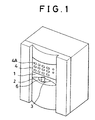
- Fig. 1 shows a general perspective view of a cup type automatic vending machine according to the present invention, where a vending corner 1 is designed, unlike conventional rectangular shaped vending corner, to provide a counter table 2 formed in a recess extending widely in lateral direction.
- the counter table 2 has a portion swelling like a dome roof and has at its central portion a cup outlet 22 for furnishing a cup 6 to a customer.
- Below the dome shaped portion of the table is a rotatably mounted vending door 3, which has a hole to match the cup outlet.
- the cup outlet is normally closed by the vending door 3, but it is opened when the hole matches the cup outlet during vending operation.
- the vending corner 1 is installed at a higher level (e.g. by 900mm) than in conventional vending machines. To be specific, it is formed immediately below a control panel 4 having selection buttons 4A.
- the vending corner 1 is recessed from the front end of the vending machine and has a wide lateral opening to furnish the cup 6 filled with
- those units for supplying cups, drinks, ice, etc. are installed at various positions within the machine.
- Fig. 2 shows how drink is injected in a cup and how the drink injected cup is moved to a vertical cup transport unit.
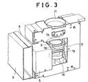
- Fig. 3 shows how the drink filled cup is moved upward by the vertical cup transport unit.
- Fig. 4 illustrates how the drink filled cup is moved up to the vending corner.
- a cup holding unit 5 having an open-close type cup grabbers 7A and 7B for grabbing the cup 6 supplied, upon cup supply command, by the cup supplying unit.
- the cup grabber also serves as a cup transport unit.
- a slider unit 9 is slidably mounted on horizontal rails 8 installed in the cabinet of the automatic vending machine.
- the cup holding unit 5 can slide on the rails 8 towards or away from the front end of the automatic vending machine.
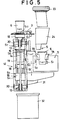
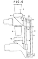
- a driving unit for sliding the cup holding unit 5 and a mechanism for opening or closing said cup grabbers 7A and 7B are shown in Figs. 7 and 8. Details of the units will be given later.
- a drink supplying unit and/or an ice making machine are/is furnished above the cup holding unit 5, whose normal stand-by position is shown in Fig. 2.
- a drink injection nozzle 10 and an ice discharging hose 11 extend from these units to the cup 6.
- a drink supplying unit blends drink according to the selection made by the customer and, through the drink injection nozzle 10, injects the blended drink into the cup 6 held by the cup holding unit 5.
- the drink supplying unit may make carbonated drink by diluting syrup with carbonated water or other soft drink by, for example, dissolving powder materials such as coffee in hot water, with sugar and milk added therein if necessary.
- the ice making machine may supply ice in the cup held by the cup holding unit 5 through ice discharging hose 11 in accordance with the selection made by the consumer.
- the cup holding unit 5 When such drink and ice are supplied to the cup, the cup holding unit 5 is slid in the direction of the arrow A shown in Fig. 2, until it is stopped at the predetermined position shown in Fig. 3.
- the operation of the cup holding unit 5 is controlled based on the output of optical position sensors provided on the transport route of the cup.
- a vertical cup transport unit 12 for moving the cup upward carries the cup to a predetermined vertical position.
- the vertical cup transport unit 12 includes a belt 14 entrain on the upper and lower pulleys 13, a driving motor 15 rotatable in two directions for driving one of the above pulleys, a vertical slider 16 mounted on said belt 14, a cylindrical coaster unit 18 mounted on the top of the vertical slider 16, and a guide rod 19 penetrating through the base of the vertical slider 16 for ensuring stabilized vertical movement of the coaster unit 18.
- the pulleys are supported by shafts 20.
- the above coaster unit 18 is located during standby period at a position a little lower than the bottom surface of the cup 6, which is moved in the direction of the arrow A of Fig. 2.
- the driving motor 15 is activated to rotate a little in normal direction, and the coaster unit 18 moves upward, thereby supporting the bottom surface of the cup to receive the cup thereon.
- the cup grabbers 7A and 7B are opened to release the cup to the coaster unit 18.
- the cup grabbers 7A and 7B are opened more widely so as not to hinder the upward movement of the cup 6.
- the driving motor 15 is again rotated in normal direction to move the coaster unit 18 up, until the coaster unit 18 is entered in a cup guide unit 21.
- the cup guide unit 21 is designed to have a larger diameter than the cup for accommodating the cup therein, preventing the cup from falling down.
- Fig. 4 shows the drink filled cup 6 coming to the counter table unit 2 of the vending corner 1. As is understood from this figure, the cup 6 is raised from below into the vending corner 1, with the vending door 3 opened to leave the cup outlet 22 open.
- the drink is offered to the consumer in the following sequence: Holding the cup released from the cup supplying unit ⁇ Injecting drink into the cup ⁇ Moving the cup to the vertical cup transport unit after drink is injected ⁇ Transferring the cup to the vertical cup transport unit ⁇ Moving upwardly the cup ⁇ Carrying the cup to the vending corner.
- a cup dropper 23 is operated to allow the cup to pass through a cup chute 24.
- the cup is grabbed by the cup grabbers 7A and 7B, after which the cup is filled with drink injected from the drink injection nozzle 10.
- the entire cup holding unit 5 is moved sidewards through the positions indicated as Cup 1, Cup 2, and Cup 3.
- the cup is transferred to the vertical cup transport unit 12 and is lifted up to the position of Cup 4.
- cup detecting sensor S installed immediately above the cup holding unit 5.
- the sensor S generates a cup blocking signal indicative of improper arrangement of the cup as such cup interrupts the light beam generated by the sensor S.
- cup grabbers 7A and 7B are loosened slightly so that the cup is placed in normal position between the cup grabbers 7A and 7B.
- a cup rest (not shown) is provided to support the bottom surface of the cup. This cup rest is provided, for example on said rails 8. Further, it is designed to be freely movable upward and downward so that, even when a cup with different height is used, the top of the cup is always aligned with the cup grabbers 7A and 7B.
- the cup In order to prevent falling down of the cup 6 or spilling of drink caused by contact of the cup rest with the cup 6 during cup transport, the cup is moved not in an exact upright position along the rail 8 but moved in slightly tilt condition (tilt about 5 degrees) with respect to a vertical line while ascending the rails.
- a cup disposal outlet 31 and a drain bucket 32 are provided below the position of Cup 2.
- a drink prepared during power failure should not be sold for hygienic reasons. Furthermore, it hinders subsequent sale if it remains. Accordingly, wherever the cup is on the transport route, such cup is moved to the position of Cup 2 when the power is restored, and disposed away by opening the cup grabbers 7A and 7B.
- the vertical cup transport unit 12 If power failure has occurred when the cup is in the ascending process from the position of Cup 3 to position Cup 4, the vertical cup transport unit 12 is moved in reverse direction to lower it when power is restored. It is then transferred to the cup grabbers 7A and 7B at the position of Cup 2 and is disposed away. In so doing, it is thus possible to take remedial actions in case of power failure during vending operation and to offer only fresh drink to the customer, allowing the machine to continue its vending operation.
- the cup holding unit 5 is provided with a slider unit 9 which is slidably mounted on the rails 8. Further, this slider unit 9 is furnished with a cup holder 25 having a pair of cup grabbers 7A and 7B.
- the slider unit 9 is driven by a driving unit 9A for reciprocal motions on the rails 8.
- the driving unit 9A has a pinion 27 engaged with a rack 26 on the back of the rails 8 and a driving motor 28M.
- the slider unit 9 also has two sets of paired rollers 29 for supporting an projection 26A having a rack 26 by pinching the upper and lower sides of the projection 26A, and a pair of rollers which may move rotatably within a roller receiver 35 installed on the lower end of the rail 8.
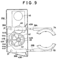
- the cup grabbers 7A and 7B are each connected at their respective ends with one ends of the operating levers 38A and 38B, respectively, pivotally supported on a pair of shafts 37 and 37 which are installed on the base 25A of the cup holder 25, through arms 39A and 39B as shown in Figs. 9 - 12.
- the operating levers 38A and 38B are pushed by the spring 40A and 40B mounted on the upper base frame 25B of the cup holder 25 in opposite directions.
- the other rotating ends of the operating lever 38A and 38B are bent to each other and are provided at their ends with projections 41A and 41B which are in contact with the cam 42.
- the projection 41B on the operating lever 38B is provided above the projection 41A of the operating lever 38A.
- cam surface 44 The peripheral surface of the cam (hereinafter referred to as cam surface) 44 is composed of; smooth cam surfaces 44a and 44b in contact with the projections 41A and 41B, respectively, as shown in Figs. 10 and 12; a concave cam surface 44c in contact with the projection 41A; and a convex cam surface 44d in contact with the projection 41B.
- the cam surface 44d shown by solid line is provided above the cum surface 44c shown by broken line. Since these cam surfaces 44a, 44b, 44c and 44d are at different distances from the center of the cam shaft 43, the open distance between the cup grabbers 7A and 7B varies according to the angular position of the cam.
- the cam 42 is rotated by the cam driving unit 45 in the range of +180° to -180° with respect to the standby position or status shown in Fig. 10.
- the cam driving unit 45 includes a driving motor 46, a speed reducing device 47, a driving gear 48 and a cam driving gear 49.
- the gear 49 is securely mounted on a lower portion of the cam rotating shaft 43 of the cam 42.
- the mechanism and the operation of the cup grabbers 7A and 7B in the cup holding unit 5 as described above can be better understood in reference to the plan view, Fig. 9, of the cup holding unit 5 and Figs. 10 to 12 showing its operation.
- the projections 41A and 41B of the rotating ends of the cup grabbers 7A and 7B are in contact sequentially with the concave and convex cam surfaces 44a, 44b, 44c and 44d (or 44a, 44b, 44e and 44f), and the grabbing operation by the cup grabbers 7A and 7B is controlled by the reciprocal angular movements of the cam 42 over a given rotational domain.
- the operating levers 38A and 38B can swing fully about their shafts 37, in opposite directions under the tensions of the springs 40A and 40B, thereby opening the cup grabbers 7A and 7B.
- Fig. 10 shows the condition of the grabbers in standby status or stanby position where the cup supplied is received and grabbed by the grabbers.
- the projections 41A and 41B are at the same rotational, but upper and lower, position, respectively, and are in contact with the common cam surface 44a, keeping the operating levers 38A and 38B parallel to each other.
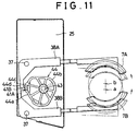
- Fig. 11 shows that the cup received is displaced from position "a" to position "b" under the drink injection nozzle. With such small displacement, it is possible to receive drink P dripping from the drink injection nozzle 10 completely into the cup as shown in Fig. 13, and also to prevent contaminating the cup and grabbers. This operation is performed as follows:
- the strokes are different for the two cup grabbers 7A and 7B. Different strokes may be attained by, for example, allowing a larger displacement for the cup grabber 7B than for the cup grabber 7A, to thereby grabbing the cup and at the same time displacing the center of the cup 6 from the point "a" (cup dropping position) to the point "b" (drink injection point) in Fig. 11.
- the cup 6 is moved from the position shown by two-dot phantom circle in Fig. 13 to the position of solid circle, so that the cup 6 is placed right below the nozzle outlet 10A of the drink injection nozzle 10.
- the drink from the drink injection nozzle 10 is injected into the cup 6, and drink P, if any, dripping from the nozzle at the end of the injection falls into the cup 6, so that spilling of the drink out of the peripheral portion of the cup will not take place.
- cup grabbers 7A and 7B In order to ensure firm grabbing of the cup, an additional force is applied to the cup grabbers 7A and 7B against the force of the springs 40A and 40B as compared to the case of Fig. 10.
- the cup grabbers 7A and 7B are brought closer to each other, and then integrally moved toward the drink injection nozzle 10.
- Fig. 12 shows the cup grabbers 7A and 7B opened to release the cup, with both projections 41A and 41B being in contact with the cam surface 44b.
- a rotating disk (not shown) is furnished on top of the cam 42, and a projecting plate (not shown) is provided on the rotating disk.
- a plurality of sensors for detecting the rotational angle of the rotating disk are furnished on the peripheral portion of the projected plate. The rotational angle is detected when the projecting plate traverses a given light beam.
- the distance between the cup grabbers 7A and 7B of the cup holding unit 5 is adjusted so as to grab any cup of any size.
- the height of the cup rest 30 is also adjusted for the same purpose.
- a vending signal indicative of the choice is generated, which causes the cup supplying unit to release a cup to the cup holding unit throught the cup chute 24.
- the cup is held there. Should the cup be trapped within the cup chute 24 or held improperly, e.g. tilted in the cup holding unit 5, the cup detecting sensor S detects such trouble, and a measure is taken to stop the current vending operation or the adjust the width of the cup grabbers 7A and 7B so that the grabbers may regrab the cup properly.
- the cam driving unit 45 is started to operate, the cup 6 is moved to the position, shown in Fig. 11, closer to the drink injection nozzle 10.
- ice and/or drink supplied from the ice making machine and/or drink supplying unit, respectively, is injected into the cup 6.
- the cup is transferred to the vertical transport unit 12 by the driving unit 9A as shown in Fig. 8.
- This transfer is completed at when the coaster unit 18 of the vertical cup transport unit 12 receives the cup by supporting thereon the bottom surface of the cup 6.
- the cam driving unit 45 is then operated again to open the cup grabbers 7A and 7B as shown in Fig. 12, freeing the cup 6 on the coaster unit 18.
- the vertical cup transport unit 12 is moved upward again to lift up the coaster unit 18.
- the cup grabbers 7A and 7B are brought to the standby positions for the next vending operation.
- the vending door 3 and the cup outlet 22 are opened during the upward movement of the coaster unit 18.
- the cup 6 placed on top of the coaster unit 18 is brought to the vending corner 1 and remains on the coaster unit 18. Therefore, the customer can easily take the cup out from the vending corner 1 by simply grabbing the cup lightly. Moreover, the customer does not have to bend himself or crouch for the cup because the vending corner 1 is positioned at a higher position than in the conventional type vending machine.
- the coaster unit 18 is lowered to the original position and is brought to the standby position for the transfer of the next cup. This completes a sequence of vending operations.
- the drink filled cup is moved to a container for disposition when the operation is resumed.
- FIG. 14 This figure shows a cup “b” caught in the chute 24, a cup “c” misplaced on the cup grabbers 7, and a cup “d” tilted in between the cup grabbers 7. A cup will be placed properly (cup “a”) in upright position within the cup grabbers 7 if no such problems take place.
- the vending machine of the invention is provided with a cup detecting sensor S, which is mounted immediately above the position where the cup is dropped from the cup dropper 23 is grabbed correctly.
- a cup detecting sensor S which is mounted immediately above the position where the cup is dropped from the cup dropper 23 is grabbed correctly.
- a transmission type optical sensor is used as the cup detecting sensor S, which may discern troubles from detection signals indicating how the light beam from a light emitting unit Sa is interrupted by a cup before it reaches reaches a light receiving unit Sb.
- Fig. 15 is a flow chart for such detection.
- ON-state of the sensor S corresponds to the situation where the light receiving unit Sb is receiving light
- OFF-state of the sensor S corresponds to the situation where the light receiving unit Sb is not receiving light.
- the vending operation is stopped in this case (step 54).
- judgment 52 is YES, the sensor is functioning. Then, the state of the sensor is checked (judgment 55). If the sensor is in OFF-state, a next judgment 58 is carried out. If it is in ON-state, an observation is made if the ON-state lasts more than 1 second (judgment 56).
- step 57 if the judgment 55 is NO, and if the sensor is not turned off from ON status for more than 1 second (YES in judgment 56), it is concluded that the cup to be supplied has not reached to the position of the sensor even after 1 second, so that the cup is either trapped in the middle of the route or the cup has not been released at all.
- the vending operation is then stopped in this case (step 57).
- the critical time for making a decision is set to 1 second. This is because 1 second is normally a good time for most cups delivered to the detector point, even when the cups are temporarily trapped on the delivery route.
- step 61 vending operation is continued (step 62).
- step 60 it indicates that the cup 6 is caught at an upper portion of the grabber 7 or the cup is tilted and not positioned between the grabber 7, the cup blocking the light beam. Therefore, the vending is stopped in this case (step 60).
- critical time for judgement is set to be 1 second. This is because improper placement of a cup, e.g. tilted in the grabbers 7, may often be corrected naturally within 1 second, so that the vending operation may be continued.
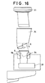
- the cup rest 30 supports the bottom of the cup. It is noted that the cup rest 30 is freely movable upward or downward and its height may be adjusted so as to properly receive a cup of any given height. It is also noted that the cups having different sizes are released from the cup droppers 23A to 23C.
- the cup grabbers 7A and 7B are opened as shown in Fig. 17. That is, the cam 42 is rotated as shown in Fig. 12 so that the projections 41A and 41B are brought to the cam surface 44b. In so doing, the cup 6, misplaced as shown by two-dot phantom line, will obtain its normal position shown by solid line. The cup is then placed on the cup rest 30 and is grabbed by the cup grabbers 7A and 7B in correct upright position. Therefore, drink is injected subsequently.
- the ON-state of the sensor S indicates that the sensor is receiving light in the light receiving unit Sb.
- the OFF-state of the sensor S indicates that the light beam is interrupted and does not reach the light receiving unit Sb.
- the cup detecting sensor S judges whether a change from OFF ⁇ ON has occurred (judgment 71). If the cup is dropped correctly in position, the cup will interrupt the light beam once only briefly, thereby turning OFF the sensor for a moment and immediately turning it ON. Thus, the judgment 71 will be YES in that case and it is concluded that the cup is neither tilted nor stuck in the cup holding unit 5. In this case, therefore, the cup holding unit 5 is activated to grab the cup (step 72), and further drink vending operation is continued (step 73).
- step 78 judgment 71 is repeated. If it is found in the second step 79 that the cup 6 is held correctly in position, the judgment 71 will be YES. Then step 72 is carried out, and the drink vending operation is continued (step 73).
- the judgment 71 will be again NO, and the judgment 74 will be YES. Since the flag remains set, the judgment 75 is YES, and consequently the vending operation is stopped (step 79).
- This cup type automatic vending machine may also provide carbonated beverages, so that the machine is provided with a carbonator and carbon dioxide gas cylinder for making carbonated water.
- the carbon dioxide gas pipe from the gas cylinder is bifurcated for provide the gas to carbon dioxide gas nozzles 80 and 80 above the upper opening of the cup chute 24 and directed thereinto, as shown in Fig. 14.
- a released cup 6 passes past the detecting sensor S within a predetermined period of time, it interrupts the light beam to generate a detecting pulse.
- carbon dioxide gas (CO2) blown from the carbon dioxide gas nozzles 80 and 80 is used to blow the cup off the cup chute 24.
- Fig. 19 shows the arrangement of the piping between the nozzles and the carbon dioxide gas cylinder containing the gas for manufacturing carbonated water.
- the carbon dioxide gas is sent from the gas cylinder 83 to the carbonator for making carbonated water and to the syrup tank for pressurizing the syrup to be discharged.
- Carbon dioxide gas is supplied through a branching pipe 82 to the carbon dioxide nozzles 80 and 80 via an electromagnetic valve 81.
- the ON-state of the sensor S indicates that the sensor is receiving light in the light receiving unit Sb.
- the OFF-state of the sensor S indicates that the light beam is interrupted and does not reach the light receiving unit Sb.
- the cup detecting sensor S judges whether a change from OFF ⁇ ON has occurred (judgment 91).
- the judgment 91 is YES. Then, the cup grabbing operation (step 92) of the cup holding unit 5 below the sensor S is performed to carry out further vending operation (step 93). However, if the judgment 91 is NO, and sensor is not turned OFF, and the sensor is kept ON for 1 second with the judgment 94 being YES, it indicates that the cup did not drop past the sensor S in 1 second after it is released, and that it is stuck in the middle of the cup chute 24. In this case, after a flag check (judgment 95), a flag is set (step 96) because no flag has been set.
- electromagnetic valve 81 is opened to blow carbon dioxide gas (CO2) from carbon dioxide gas nozzles 80 and 80 (step 97) into the cup chute 24, to thereby blowing the cup stuck in the cup chute 24 off the chute. Then, the electromagnetic valve 81 is closed to stop the carbon dioxide gas (step 98).
- CO2 carbon dioxide gas
- step 98 procedures starting from the judgment 91 through 97 are repeated if the cup 6 remains in the chute.
- the judgment 91 is turned to YES.
- step 92 is carried out and drink vending operation is continued (step 93).
- the judgment 91 turns out to be NO again, and the judgment 94 YES, the judgment 95 YES since the flag remains set (judgment 95). Then the vending operation is stopped (step 99).
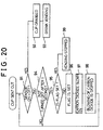
- the horizontal cup transport unit 50 recedes (to its standby position)(101).
- the standby position sensor S1 (102) detects that the horizontal cup transport unit 50 has returned to the standby position
- next purchasing order made by the same customer or different customer may be accepted. That is, coins may be deposited (103) and drink may be selected on the selection buttons 4 (104).
- the selection buttons 4 When one of the selection buttons 4 is pressed,signals indicative of the next order is issued (105), and the next cup is released from the cup dropper 23.
- the cup thus released is grabbed by the cup holding unit 5 during injecting drink from the drink injection nozzle 10 in the cup for vending operation (106).
- the horizontal cup transport unit 50 is standing by for the next move when the drink injection is completed (107).
- the cup presence detecting sensor S12 of the vertical cup transport unit 12 detects that the cup was taken out (110).
- the vertical cup transport unit 12 then moves downward (101).
- the low position detecting sensor S4 detects the unit 12 (112).
- the horizontal cup transport unit 50 is allowed (113) to move forward.
- the horizontal cup transport unit 50 may move forward provided that the drink injection has been completed (108).
- the cup is moved onto the coaster unit 18 of the vertical cup transport unit 12 waiting for the cup at the low position. Then, the cup is moved upward following the normal lifting procedure (109), up to the vending position and protrudes into the vending corner 1.
- the unit 12 is then returned to the initial state (100) to prepare for the next operation.
- the vending operation for the next vending such as depositing coin, selection of a drink, and injection of drink into the next cup may be performed in advance on the condition that the cup for the present customer is transported to the vending corner 1, saving preparation time (or waiting time) for the next customer. Subsequent operation may be started as soon as the present customer takes up his cup. This is in strong contrast to conventional machines which may start the entire operation only after the customer takes his cup. It is thus a great advantage of the invention that the waiting time is significantly reduced for the customer, as compared with the conventional vending machines.
- the invention provides the following measures:
- the automatic vending machine is designed to judge the nature of the trouble it has encountered and judge if it is possible to recover its normal condition or not, and, if it is, the above mentioned self-control operation (I) and (II) are performed and returns to the standby condition.
- the transport units 50 and 12 can be stopped for some other reasons such as malfunctions of the sensors S1 to S7.
- the cup holding unit 5, the horizontal cup transport unit 50, and the vertical cup transport unit 12 are not operated simultaneously. That is, when any one of these units is operated, the remaining units remain stopped in certain non-operating conditions. Therefore, it is possible to judge the operational condition (operating mode) of the operating unit from the operational conditions (operating modes) of the remaining units. Possible combinations of such operational modes are shown in Fig. 23.
- Fig. 24 shows the flow of normal operations of these units 50, 12 and 5.
- the horizontal cup transport unit 50 sequentially takes positions: rear position a1 ⁇ intermediate position a2 ⁇ front position a3. During these steps A, the unit 50 has a cup and is transporting it forward. On the other hand, the vertical cup transport unit 12 is moved to the a position (e0) and remains there. When the horizontal cup transport unit 50 arrives at a front position (a3), the vertical cup transport unit 12 moves slightly upward, taking positions: low position c1 ⁇ cup supporting position (c2), and receives the cup thereon. In step C, a cup is also present in the unit.
- the coaster unit 18 comes to a position where it can support the cup
- the cup holding unit 5 undergoes an opening operation by taking: holding position f1 ⁇ opening position f2.
- the vertical cup transport unit 12 moves upward from a cup supporting position d1 to the vending position d2, bringing the cup to the vending corner 1.
- the cup is also present in the unit.
- the horizontal cup transport unit 50 moves backward from a front position b1 to a rear position b2 and returns to its standby position.
- no cup is present in the unit.
- the vertical cup transport unit 12 moves down slightly from the vending position e1 to a standby position e2 and stops there.
- the next vending signal (v) is given, it moves down to a low position e3 and returns to its initial status e0.
- the cup holding unit 5 assumes: opening position f2 ⁇ opening position f3 while the vertical cup transport unit 12 is moves from a cup supporting position d1 to the standby position e2 through positions d2 and e1. It is moved from the opening position f3 to a standby position f4 while the vertical cup transport unit 12 is moved from the standby position e2 to the low position e3.
- a cup is dropped (g), and the unit waiting for the cup receives the cup.
- the unit moves from a standby position f5 to a holding position f6, and returns to its initial position f0.
- the steps A, C, and D are related to the transportation of the cup. If the cup stops at an intermediate position in the steps, the drink filled cup is disposed, and the units returns to their respective standby positions.
- Fig. 25 is a flow chart of steps followed by the horizontal cup transport unit 50 in case abnormal stop (arising from, e.g. power failure) has occurred during the steps A.
- the vertical cup transport unit 12 When the stop has occurred during horizontal transportation of the drink filled cup, the vertical cup transport unit 12 remains at the low position, so that the low position detecting sensor S4 will detect the unit 12 (120). Therefore, based on the detection, a move signal is given (121) to the horizontal cup transport unit 50. The horizontal cup transport unit 50 is now returned to an intermediate position (122) where it is opened (123) and disposes the cup (124), and then returns to the standby position.
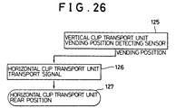
- the horizontal cup transport unit 50 stops in the steps B, procedures flow as shown in Fig. 26. In this case the horizontal cup transport unit 50 is in the middle of the process to return to its standby position. Since in this case the vertical cup transport unit 12 is remaining at the vending position, the active vending position detecting sensor S1 1 detects the unit 12 (125). Therefore, based on such detection, a move signal is given to the horizontal cup transport unit 50 (126). The horizontal cup transport unit 50 continues the backward motion and returns to the standby position (127).
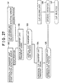
- Fig. 27 shows the flow of steps followed when the vertical cup transport unit 12 is stopped in the step C.
- the coaster unit 18 is sopped at a position slightly moved upward to support the bottom surface of a cup. Since in this case the horizontal cup transport unit 50 is at a specified front position, the front position detecting sensor S3 detects the unit 50 (130). At the same time, the holding position detecting sensor S9 detects the cup holding unit sitting at the position to hold a cup (131). Based on the detection of these two sensors S3 and S9, a move signal is given to the vertical cup transport unit 12 (132). The vertical cup transport unit 12 is moved down to the low position and then returns to the position to support the next drink filled cup delivered there in the next vending operation (133). When the vertical cup transport unit 12 arrives at the low position, another move signal is given to the horizontal cup transport unit 50 (134). When the horizontal cup transport unit 50 moves to an intermediate position (135), the cup holding unit 5 opens (136) to free the cup for disposition (137).
- Fig. 28 shows the flow of steps to be followed when an abnormal stop has occurred during the transportation of the cup by the vertical cup transport unit 12 in the steps D.
- the cup holding unit 5 is opened, and the vertical cup transport unit 12 bearing thereon the coaster unit 18 is stopped midway to the vending corner 1.
- the front position detecting sensor S3 detects (140) the horizontal cup transport unit 50 sitting at the front position.
- the cup holding unit 5 is also opened, and the open position sensor S9 detects this condition (141). Based on the detection by these two sensors S3 and S9, a move signal is given to the vertical cup transport unit 12 (142) which comes down to the cup supporting unit (143).
- the cup holding unit 5 grabs the drink filled cup (144).
- a move signal is given to the horizontal cup transport unit 50 (145), so that it moves to an intermediate, position (146) where the cup holding unit 5 is opened (147), disposing the cup (148). Thereafter, the horizontal cup transport unit 50 returns to its standby position.
- Fig. 29 shows the flow of steps to be followed when the vertical cup transport unit 12 is stopped during the vertical motion in the step E.
- the horizontal cup transport unit 50 is located at a position behind the standby position since it was stopped when it was receding, based on a vending signal.
- the unit 50 is detected by the active rear position detecting sensor S1 (150), which provides a move signal to the vertical cup transport unit 12 (151). The unit thus returns to its initial standby position (152). When next vending signal is generated, another move signal is given to the unit 12 to move it to the low position (153).
- FIGs. 30A and B show a mechanism of a cup outlet 164.
- the cup outlet 164 is formed in the central region of a cover member 165 which has a sectional spherical surface and is mounted in the recess 2b in the front end 2a.
- a vending door 166 is provided inside the cover member 165.
- the vending door 166 is a fan-shaped member having a spherical surface coaxial with the spherical surface of the cover member165, with their spherical center at PC.
- the vending door 166 is pivotally fixed on a shaft 167 which extends vertically through the center PC. The longitudinal direction of the vending door 166 coincides with the shaft 167.
- the shaft 167 is driven by a motor 169 via a speed reduction unit 168.
- a cup presence detecting sensor S12 which consists of a pair of light emitting element and a light receiving element for detecting the presence of a cup 6.
- the coaster unit 18 serves to move the cup 6 from its standby position 18 (marked by a dotted line) to the cup outlet 164.
- the vending door 166 has an opening 172 which is larger in diameter than the cup 6.
- the cup outlet 164 is an elongate hole extending longer than the opening 172 in the moving direction of the vending door 166.
- the motor 169 As the motor 169 is activated, its power is transmitted to the shaft 167 through the speed reduction unit 168, and the shaft 167 is rotated in the direction defined by the rotational direction of the motor 169, so that the vending door 166 is moved in a direction appropriate to open/close the cup outlet 164.
- the vending door 166 is stopped at the position shown by solid line in Fig. 31.
- the door is rotated counterclockwise in the figure until the opening 172 comes right above the coaster unit 18.
- the coaster unit 18 may come out through the opening 172 of the vending door 166 and the cup outlet 164, and the cup 6 placed on the coaster unit 18 is served to the customer.
- the dust 173 on the vending door 166 remains on a portion of the door 166 moved off the opening 172 so that the dust is prevented from entering into the cup 6 through the opening 172. This is possible because the size of the opening 172 is larger than the cup outlet 164 so that the dust 173 is collected on the vending door 166 outside the opening 172.
- vending door 4 closes to cover the cup outlet 164, and the coaster unit 18 is receded at the position shown in Fig. 30(A).
- control unit start driving the motor 169 to open the vending door 166 immediately before the cup 6 is placed on the coaster unit 18, and then moves the opening 172 to the position directly above the coaster unit 18.
- the control unit moves the coaster unit 18 upward to bring the cup 6 extending partly out of the cup outlet 164 as shown by solid line in Figs. 32 A and B.
- the lower end of the cup 6 is now located at a level higher than the lowermost end of the cup outlet 164. Accordingly, the customer can take out the cup 6 without hitting the cup against the edge of the cup outlet 164.
- the cup presence detecting sensor S12 no longer detects the cup 6. As the results the control unit moves the coaster unit 18 back to the standby position. The vending door 166 is moved back to the close position to close the cup outlet 164 .
- cup outlet 164 is enlongate such that it is larger than the cup 6, and that it extends longer than the opening 172 in the moving direction of the vending door 166. This makes it possible to prevent the dust on the vending door 166 from falling in the cup 6.
- the cover member 165 and the vending door 166 have coaxial spherical surfaces centered at PC. This makes it possible to reduce the gap between the cover member 165 and the vending door 166 as small as possible. Accordingly, dust is prevented from entering through this gap.
- the cup presence detecting sensor S12 is designed to detect the cup 6 inside the vending door 166, so that it will not be subject to contamination that would otherwise arise from dust, insects, and spilt beverage. Thus, the cup 6 may be properly detected by the sensor.
- cup outlet and the vending door are formed to have sectional spherical surfaces in the above example, they are not limited to spherical ones, so long as their surfaces have inclination towards the customer.
- the vending door is pivotally mounted on the vertical shaft for opening and closing the vending door.
- opening and closing mechanism for the vending door is not limited to this.
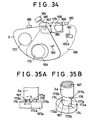
- the drive shaft 167 of the door 3 is operably connected with a one-way clutch 179 by means of a spring pin 170 fixedly mounted on a lower portion of the drive shaft 167 for transmitting the rotational power, and of slotted members 171 and 171 engaging with the spring pin 170.
- This one-way clutch 179 is engaged with the drive shaft 167 with a gap between them, which gap allows vertical motion of the clutch 179 relative to the shaft 167 over the slotted members.
- the spring pin 170 prohibits the rotational motion of the clutch relative to the shaft. Normally, the clutch is forced upward by the action of a spring coil 178. As shown in Figs.
- a pair of triangular projections 174 and 174 are formed on the shaft of this one-way clutch 179.
- the triangular projections are angularly spaced apart by 180 degrees and located at the opposite side of the shaft.
- the triangular projections each have a vertical surface 173a on one end which is facing the direction of the action (counterclockwise: solid line arrow "a") of the one-way clutch 179 and a tapered surface 173b on the other end facing the non-acting direction (clockwise: dotted line arrow "b") of the clutch.
- the base 3a of the vending door 3 is engaged with the top of the drive shaft 167 and rotatably supported by the pin 175 such that the base 3a is rotatable with respect to the drive shaft 167 but not removable from the drive shaft 167.
- the base 3a of the vending door 3 On the lower end surface of the base 3a of the door, are formed triangular projections 176 and 176 similar to the projections 174 and 174, having vertical surfaces 177a and tapered surfaces 177b.
- the one-way clutch 179 is forced upward and the base 3a of the vending door 3 is forced downward by a coil spring 178, so that the joint portions A of the one-way clutch and the base engage with each other.
- the drive shaft 167 is rotated in normal direction (counterclockwise direction) by a driving motor 169
- the one-way clutch 179 mounted on the lower portion of the drive shaft is rotated together.
- the vertical surfaces 173a of the projections 174 of the one-way clutch 179 will engage the vertical surfaces 177a of the projections 176 of the door base 3a.
- the rotational force is transmitted from the clutch to the base 3a of the vending door, which in turn rotates the vending door 3 to the open position.
- the circular opening 172 formed in the vending door 3 matches the cup outlet 164, a cup may be set therein.
- a torsion spring 180 is provided between the base 3a of the vending door 3 and the one-way clutch 172. When the vending door 3 is opened, the torsion spring 180 is tightened to accumulate the torsional force, which acts on the base 3a in the direction to close the vending door 3.
- a door opening detecting sensor 181 is provided for stopping the motor 169 by detecting the vending door 3 reaching the position shown by one-dot phantom line in Fig. 34.
- This door opening detecting sensor 181 is an optical detecting sensor having a pair of light emitting element and a light receiving element, capable of detecting the opening of the vending door 3 when the shielding piece 182 interrupts the light impinging on a lower portion of the vending door 3 (dotted line 182a).
- a stopper 183 prevents excessive movement of the vending door 3 that may happen when the door opening detecting sensor 181 does not operate properly.
- a door closing detecting switch 184 is provided on the outer periphery of the one-way clutch 179 for detecting the rotational position of the drive shaft 167 at the end of closing the vending door 3.
- This door closing detecting switch 184 is constructed to operate on the protrusions 185 formed on the periphery of the one-way clutch 179.
- the motor 169 is stopped when switch is in operation (ON).
- a stopper 186 is provided for preventing excessive rotation of the vending door 3 in the closing direction.
- the driving power of the motor 169 is transmitted to the drive shaft 167 through the speed reduction and transmission unit 168, to rotate the shaft 167 in the counterclockwise direction.
- the power is transmitted to the one-way clutch 172 via the spring pin 170, rotaing the clutch 172 in the counterclockwise direction.
- the vending door 3 is rotated counterclockwise also, since the triangular projections 174 and 176 of the one-way clutch 172 and the vending door 3, respectively, are firmly engaged with each other on the vertical surfaces 173a and 177a under the action of the coil spring 178 pushing the one-way clutch 172 upward.
- This rotational motion tighten the torsion spring 180, so that the spring force acting in the clockwise is accumulated.
- the motor 169 is rotated in the reverse direction to rotate the drive shaft 167 in the clockwise direction.
- the one-way clutch 179 is also rotated in the clockwise direction.
- the vertical surfaces 177a of the projections of the vending door 3 are pushed against the vertical surfaces 173a of the projections of the one-way clutch 179.
- the vending door 3 is thus rotated in the clockwise direction.
- the motor 169 is stopped.
- the vending door 3 is also stopped by the detection signal from the door closing detecting switch 184.
- the cup outlet 4 overlies the vending door 3, so that the the opening 18 is closed.
- the door closing detecting switch 184 is in operation in association with the rotational motion of the one-way clutch 179. Therefore, this operational condition is interpreted as a failure mode of the door opening operation.
- vending door 3 will not move further, although the motor 169 continues to rotate, until the detection signal is generated by the door closing detecting switch 184 to stop the operation of the motor 169.
- the one-way clutch 179 is stopped at an advanced clockwise position with respect to the shaft 166a of the vending door 3 stopped by hand. Under this condition, the projections are mutually disengaged with each other.
- the vending door 3 is rotated to the normal closing position by the torque of the torsion spring 180, and thereafter normal operation may be continued.
- the vending door 3 will remain trapped by the fingers, but the motor 169 continues to rotate beyond the predetermined stopping position.
- the one-way clutch 179 advances clockwise by 180 degrees relative to the shaft 166a of the vending door 3 stopped by the fingers, the tapered surfaces 177b and 174b of the projections 176 and 174 meet and override each other, thereby pushing down the one-way clutch 179 against the force of the coil spring 178 as the clutch continues to rotate.
- the tapered surfaces 177b and 174b will slip thereafter, so that the rotational torque of the motor 169 will not be transmitted to the vending door 3. Thus, it will not lead to serious injury to the fingers caught by the door, assuring safety.
- the vending door 3 is unable to move by the action of the stopper 186.
- the operation thereafter is the same as described in (2)-(3) above.
- the door 3 may be rotated in the clockwise direction under the torsional force of the spring 180, by disengaging the vending door 3 from the one-way clutch 179 by removing the stopper 186 and by pushing the one-way clutch 179 down.
- the vending door 3 may be then moved behind the cover member 165. (This is convenient in cleaning up the inner surface of the cover member 165 and the upper surface of the vending door 3.)
- a reason for this is that it is desirable to bring the cup 6 to the position (Cup 3) beneath the vending door 3 only after the vending door 3 is completely open. Then, since the dust on the vending door 3 has fallen already by the time the cup reaches the position, it does not fall into the cup 6.
- the vending door 3 should start its opening operation soon after the cup begins to move from the drink injection position, and complete the operation before the cup reaches the position.
- the timing should be variable and set according to the conditions of the location of the vending machine installed.
- Locations include, for example, a location for a fixed group of customers and a location for general customers.
- the opening of the vending door 3 may be controlled by a timer.
- the starting time of the door opening operation may be set such that the operation begins after a predetermined period of time following the beginning of cup transportation. It is also possible to set the timer so as to start the operation after completion of the cup transportation. This may be accomplished by providing a position detecting sensor arranged at some reference point in the cup transportation route, for detecting an arriving cup to initiate the opening of the vending door 3.
- Another approach to control the door opening operation is to establish timing between the door motion and the cup position.
- Typical timing includes:
- a door opening-closing detecting switch S11 (sensor) is provided on the vending door 3, along with the position detecting sensors S1, S2 and S3 provided at the standby position, the intermediate stop position, and the front stop position, respectively, of the horizontal cup transport unit 50 and the position detecting sensors S4, S5, and S6 provided at the standby position, the low position, and an intermediate position, respectively, of the vertical cup transport unit 12, and a sensor S7 at the vending position.
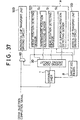
- Fig. 37 shows a block diagram of a control circuit for switchably controlling both timer setting and timing setting systems using these sensors by selecting one of the systems by a setting means.
- a variable timer T outputs, after predetermined time, a signal to initiate the operation of vending door driving circuit 3D. This establish a door opening operation time.
- This vending door driving circuit 3D receives detection signals from the front position detecting sensor S3, the intermediate position detecting sensor S2, the rear (standby) position detecting sensor S1, and the cup supporting (intermediate) position sensor S5. Which of these signals is to be used in driving the vending door driving circuit (3D) depends on a decision made in advance by the setting means.
- the vending door driving circuit 3D is started by the signal transmitted from the selected one of the sensors S1 to S5 indicating the arrival of the cup at that position, and accordingly the door opening operation is started.
- the horizontal cup transport unit driving circuit 50D is connected to the front position detecting sensor S3 which outputs a signal indicative of the absence of the cup at that position.
- the circuit is activated through a logic circuit 60 only when a signal indicative of the completion of drink injection is received. Accordingly, only the cup transport operation proceeds after the completion of drink injection and until the arrival of the cup at the front position.
- the detection signal from the front position detecting sensor S3 is also given to the vertical cup transport unit driving circuit 12D.
- the vertical cup transport unit 12 starts its operation to slightly lift the coaster unit 18 to the cup supporting position (the intermediate position).
- timing setting based on the selected positions of the cup suitable for opening the vending door 3 at desired time, by selecting the sensors from the sensors S1, S2, S3 and S5 accordingly.
- the entire timing setting system is shown by Frame A indicated by a one-dot line.
- specifying means B is provided for selecting either the variable timer T, which is a timer-type setting means, or the timing-type setting means A.
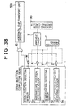
- Fig. 38 shows a control block diagram illustrating time setting by the timer system, wherein the vending door is set to open at a predetermined time after the cup arrived at a specified reference position in the route.
- the above reference position may be any of the positions of the sensors S1, S2, S3 and S5 (rear, intermediate, front and cup supporting positions, respectively).
- Block E shown by a one-dotted line serves as an input means to the timer T.
- the detecting signals output from the sensors S1, S2, S3 and S5 are selectively input to the variable timer T via switches X, Y, Z, and W of a selection unit C. Accordingly, receiving a detection signal from the selected sensor, the variable timer T is activated. That is, when the cup arrives at the predetermined reference position, the variable timer T is activated to drive the vending door driving circuit 3D after a predetermined time.
- the main unit 450 of the vending machine has a control panel 4 at an upper center of the front surface.
- the control panel 4 is provided with regular arrays of various buttons for selecting various types of drinks.
- a coin slot 4f and a refund button 4g are arranged adjacent the bottoms.
- This model shown in the figure is designed to provide carbonated drinks flavored with syrups and coffee drinks.
- Selection buttons 4a are provided for the carbonated drinks and selection buttons 4b to 4e are for coffee drinks.
- These selection buttons for coffee drinks include the selection button 4b for the coffee with sugar and cream, the selection button 4c for coffee with sugar, the selection button 4d for coffee with cream, and the selection button 4e for black coffee. When one of these selection buttons, except 4e, is pressed, the machine will provide regular coffee blended with sugar and milk at a specified ratio.
- buttons and decrease buttons to change the amounts of sugar, cream and coffee material bit by bit in several steps.
- a set of increase/decrease indicator lamps 400 is also provided below the selection buttons 4A, which are lighted one at a time in correspondence with the selection of the increase/decrease buttons.
- the detailed arrangement of the buttons and the lamps is shown in Fig. 40. As seen in the figure, five-indicator lamps 401, 402, and 403 are aligned horizontally one for each flavor material (i.e. sugar, cream and coffee(in powder form)), so that the customers can tell at a glance how much that flavor material is increased or decreased with respect to the regular coffee.
- a sugar increase button 411 To the right of the indicator lamps are a sugar increase button 411, a cream increase button 412, and a coffee increase button 413 are arranged. Similarly, to the left of the indicator lamps are a sugar decrease button 414, a cream decrease button 415 and a coffee decrease button 416.
- the increase/decrease indicator lamps and the increase/decrease button are related in such a way that when one of the increase buttons 411, 412 and 413 is pressed, lighting shifts to the right by one step (lamp). When one of the decrease buttons 414, 415 and 416 is pressed once, the lighting shifts to the left by one step. The lamps are lit only when a customer deposited coin in the slot, when lamps at position 0 are lit (corresponding to regular coffee). If the increase/decrease button is pressed once, the lighting shifts to the position +1/-1. If the same button is pressed once more, it is shifted to the position +2/-2. A button 417 is provided for coffee without sugar or cream.
- buttons for coffee with sugar coffee is provided without sugar. If it is pressed after pressing for coffee with cream, coffee is provided without sugar and cream.
- a button 418 is provided for coffee with ice: if it is pressed, no ice is provided.
- Fig. 41 shows possible combinations of the selections of these increase/decrease buttons made for coffee with sugar and milk.
- the increase/decrease indicator lamp 400 are not lit, as shown in figure (1).
- the increase/decrease indicator lamps 400 at position 0 are lit, as shown in figure (2).
- the decrease button 414 is pressed once, the corresponding increase/decrease indicator lamp 401 at the position of -1 is lit, as shown in figure (3).
- the cream button 4b is pressed, an amount of sugar to be added in the coffee is decreased by the amount equivalent to one push of the sugar button 414.
- the quantity of sugar to be decreased is doubled.
- the increase button 411 is pressed once under the condition (4), the selection will be changed to the condition as shown in figure (5). If the increase button 411 is pressed once more, the condition returns to the regular condition, figure (6). If the increase button 411 is pressed again once or twice, the corresponding conditions of the increase/decrease indicator lamps 401 will become as shown in the figures (7) or (8), respectively.
- the quantity of sugar may be increased or decreased step by step with respect to the regular coffee in unit of a given amount (which a mount corresponds to a+ or a-). This unit may be adjusted as desired.
- the relative amount of cream and coffee materila may be increased/decreased by selecting one of the increase/decrease buttons.
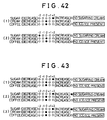
- Fig. 42 shows the case where black coffee is selected.
- the customer changes his mind to add sugar to black coffee after he has selected the selection button 4e for black coffee, he may push the increase button 411 for that purpose. If a plus (+) indication appears, sugar is added by that amount. This condition is shown in the upper figure (1).
- the increase/decrease buttons for cream 412 and 414 functions similarly as in the case of sugar button. Accordingly, it is possible to meet the demands of the customers satisfactorily.
- Fig. 43 (1) represents the selection of coffee with sugar and cream with sugar increased by two units (+2).
- the selection is made by pushing the button 411 twice. If in this case the customer changes his mind to get sugarless coffee, and pushes the no-sugar/no-cream button 417, the indication will change to one as shown in figure (2). The sugar indication is still plus (+) 2. However, since the selection made by the no-sugar/no-cream button 417 supersedes the selection made by button 411, no sugar will be added.
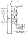
- Fig. 44 shows a control circuit for the increase/decrease indicator lamps and related driving mechanisms described above.
- a microcomputer 420 controls the order and types of the selections made by pushing corresponding selection buttons 411, 412, 413, 415 and 416, and controls lighting conditions of increase/decrease indicator lamps 401, 402 and 403 accordingly, each time one of the increase/decrease buttons for sugar, cream and coffee is selected.
- the microcomputer 420 also provide, through an inverter 422, signals for controlling the operations of a coffee motor 421, a sugar motor 422, a cream motor 423 and a coffee electromagnetic valve 424.
- a coin mechanism 426 is provided for counting coins deposited by a customer and for calculating change under the control of the microcomputer 420.
Landscapes
- Physics & Mathematics (AREA)
- General Physics & Mathematics (AREA)
- Beverage Vending Machines With Cups, And Gas Or Electricity Vending Machines (AREA)
Claims (13)
- Distributeur automatique de gobelets pour proposer des boissons versées dans un gobelet (6) libéré par une unité (23) d'alimentation de gobelets lors d'une opération de distribution, comprenant :une unité de retenue de gobelets (5) pour retenir ledit gobelet (6) libéré par ladite unité d'alimentation de gobelets (23);une sortie (22) prévue dans la partie avant (2) d'une unité principale dudit distributeur automatique ;une porte d'accès (3) pour ouvrir et fermer ladite sortie (22) etun dispositif de transport de gobelets (8, 9, 12) pour conduire ladite unité (5) de retenue de gobelets à un endroit où une boisson est injectée dans ledit gobelet (6), et à ladite sortie (22) après ladite injection de boisson et pour faire sortir en outre ledit gobelet (6) en dehors de ladite porte (3) en dehors de ladite sortie (22)
caractérisé parun dispositif de détection (S, S₁,...S₁₂) pour détecter un gobelet resté dans le dispositif (8, 9, 12) de transport de gobelets pendant une panne de courant, après que le courant a été rétabli ;un dispositif pour transporter le gobelet (6), le cas échéant, détecté par ledit dispositif de détection, en faisant fonctionner ledit dispositif de transport de gobelets jusqu'à une unité de rejet de gobelets (32) ; etun dispositif pour renvoyer ledit dispositif de transport de gobelets (8, 9, 12) dans son état d'attente si ledit détecteur ne détecte aucun gobelet (6) dans le dispositif de transport de gobelets. - Distributeur automatique de gobelets selon la revendication 1, dans lequel ladite unité de retenue de gobelets (5) est agencée pour pouvoir retenir ledit gobelet par deux mâchoires (7A, 7B).
- Distributeur automatique de gobelets selon la revendication 2, comprenant en outre :
un dispositif détecteur (S) pour détecter un gobelet bloqué dans ladite unité de retenue de gobelets (5) et un contrôleur fonctionnant en réponse à un signal reçu dudit détecteur (S) pour ouvrir lesdites mâchoires (7A, 7B) afin de jeter ledit gobelet dans ladite évacuation de gobelets quand ledit gobelet bloqué est transporté vers ladite évacuation de gobelets par ladite unité de transport de gobelets (8, 9, 12). - Distributeur automatique de gobelets selon l'une quelconque des revendications 1 à 3, caractérisé par :un dispositif de transport (8, 9) de gobelets avant-arrière pour transporter ladite unité de retenue de gobelets (5) dans des directions approximativement horizontales ;une unité de transport vertical de gobelets (12) pour recevoir et maintenir le gobelet (6) transféré à partir du dispositif de transport du gobelets avant-arrière (8, 9) et pour transporter vers le haut ledit gobelet (6) vers une contre-table (2) prévue sur la surface avant de l'unité principale dudit distributeur automatique, etune sortie de gobelets de type ouvert/fermé sur ladite contre-table, pour permettre quand elle est ouverte, audit gobelet monté par ledit dispositif de transport vertical de gobelet (12) de s'étendre au-dehors de ladite sortie (22).
- Distributeur automatique de gobelets selon l'une quelconque des revendications 1 à 4, comprenant en outre :une porte d'accès (3) pour ouvrir et fermer ladite sortie (22) ;un dispositif de détection (181, 184) pour détecter l'état d'ouverture ou de fermeture de ladite porte d'accès (3) ; etun dispositif de commande pour permettre à ladite unité de retenue de gobelets (5) de transférer le gobelet vers l'unité de transport vertical de gobelets (12) quand l'état détecté par ledit dispositif de détection est l'état ouvert de la porte d'accès (3).
- Distributeur automatique de gobelets selon l'une quelconque des revendications 1 à 4, comprenant en outre :un dispositif (S₁₂) de détection de présence de gobelet pour détecter la présence d'un gobelet à ladite sortie de gobelet (22) ;un dispositif (4F) récepteur de pièces ;un dispositif de mémoire (4A) pour permettre de choisir des boissons et de stocker l'information correspondant au choix ;un dispositif de détection (S₁₂) pour détecter si un client a enlevé son gobelet de ladite sortie de gobelets, etun dispositif (420) pour commencer le fonctionnement de la distribution, la sélection d'une denrée étant autorisée pendant le fonctionnement de distribution de boisson et la boisson choisie étant conservée en mémoire, et la boisson choisie ainsi mémorisée étant présentée au client quand le dispositif de détection de présence de gobelets détecte que le gobelet n'est pas présent dans le coin de distribution dès que le client enlève un gobelet rempli de boisson.
- Distributeur automatique de gobelets selon l'une quelconque des revendications 1 à 4, comprenant en outre :un dispositif (S₁₂) de détection de présence de gobelet pour détecter la présence d'un gobelet à ladite sortie de gobelet ;un dispositif (8, 9) pour renvoyer ladite unité de retenue (5) dans son état d'attente à condition que l'unité de retenue de gobelets ait transféré le gobelet à ladite unité (12) de transport vertical de gobelet ;un dispositif (23) pour libérer et faire tomber un gobelet (6) pour la prochaine opération de distribution ;un dispositif (10, 11) pour injecter ladite boisson choisie dans ledit gobelet ; etun dispositif (50) pour déplacer ladite unité (5) de retenue de gobelet vers ladite unité de transport vertical de gobelets lorsque ledit dispositif de détection de présence de gobelets ne détecte pas de gobelet dans ladite sortie de gobelets (22).
- Distributeur automatique de gobelets selon l'une quelconque des revendications 1 à 4, comprenant en outre :un toboggan (24) à gobelet afin de guider ledit gobelet libéré par ladite unité d'alimentation en gobelets ;un dispositif de détection de gobelet (5a, 5b) pour détecter si un gobelet est coincé dans ledit toboggan à gobelet ; etun dispositif (80) d'injection de gaz pour injecter du dioxyde de carbone gazeux dans ledit toboggan à gobelet (24) si un gobelet coincé est détecté par ledit moyen de détection de gobelets.
- Distributeur automatique de gobelet selon l'une quelconque des revendications 1 à 4, comprenant en outre :une sortie de gobelets (22) prévue dans ladite contre-table dont l'ouverture est supérieure au diamètre dudit gobelet (6) ;une porte d'accès (3) pour ouvrir et fermer ladite sortie de gobelet (22) ;un dispositif d'entraînement (167-169) pour ouvrir et fermer ladite porte d'accès (3), ladite sortie ayant, dans la direction d'ouverture de ladite porte d'accès, une taille plus grande que la taille de cette ouverture qui est couverte par ladite porte d'accès.
- Distributeur automatique de gobelets selon l'une quelconque des revendications 1 à 4, comprenant en outre :une porte d'accès (3) pour ouvrir et fermer ladite sortie de gobelets (22) ;un dispositif d'entraînement (167-169) pour ouvrir et fermer ladite porte d'accès (3) ;un dispositif de détection (S₁₂) de présence de gobelets pour détecter l'extrémité inférieure du gobelet qui a été monté jusqu'à ladite contre-table par ladite unité de transport vertical de gobelets (12) avec sa partie supérieure dépassant lors de ladite sortie de gobelets (22), dans lequel :ladite contre-table (2) présente une surface inclinée vers le client ; etladite sortie de gobelet (22) est formée dans ladite surface inclinée ; etladite porte d'accès (3) est conformée de manière semblable à la conformation de la surface inclinée.
- Distributeur automatique de gobelets selon l'une quelconque des revendications 1 à 4, comprenant en outre :une porte d'accès (3) pour ouvrir et fermer ladite sortie (22) ;un dispositif de minuterie (A, T) qui fait commencer la période de comptage à l'achèvement de l'injection de boisson dans ledit gobelet (6) ;un dispositif de détection (S₁-S₁₂) pour détecter si le gobelet (6) a été transporté vers un endroit prédéterminé dans l'unité de transport de gobelets (8, 9, 12) et,un dispositif de commande pour commander l'ouverture de la porte d'accès (3) après qu'un temps prédéterminé a été décompté par ladite minuterie (A,T) ou après que ledit dispositif de détection à détecter un gobelet audit endroit.
- Distributeur automatique de gobelets selon l'une quelconque des revendications 1 à 4, comprenant en outre :une porte d'accès tournante (3) pour ouvrir et fermer ladite sortie (22) ;un arbre d'entraînement (167) mû par un moteur (169),un embrayage unidirectionnel (179) monté sur ledit arbre (167) pour transmettre la puissance nécessaire pour entraîner ladite porte d'accès (3) quand il tourne dans une direction normale ; etun élément élastique (180) qui peut exercer une force élastique de ressort dans la direction de fermeture de ladite porte d'accès (3).
- Distributeur automatique de gobelets pour distribuer des matières en poudre mélangées en mélangeant une multiplicité de matières en poudre, conformément à l'une quelconque des revendications 1 à 12, caractérisé parune multiplicité de commutateurs de sélection (4A), un pour chaque matière en poudre, destinés à choisir la poudre ;un bouton d'augmentation/diminution (411, 416) prévu pour chaque matière en poudre afin d'augmenter/diminuer la quantité de matière en poudre à mélanger dans une unité de quantité prédéterminée, permettant ainsi d'augmenter/diminuer la quantité de matière mélangée en fonction du nombre de fois où on appuie sur le bouton (411, 416) etune pluralité de lampes d'augmentation/diminution (400) pour indiquer de manière graduelle la quantité augmentée/diminuée des matières en poudre.
Applications Claiming Priority (16)
| Application Number | Priority Date | Filing Date | Title |
|---|---|---|---|
| JP2159937A JPH0451394A (ja) | 1990-06-20 | 1990-06-20 | カップ式自動販売機 |
| JP159937/90 | 1990-06-20 | ||
| JP159940/90 | 1990-06-20 | ||
| JP15994090A JP2962774B2 (ja) | 1990-06-20 | 1990-06-20 | カップ式自動販売機 |
| JP169925/90 | 1990-06-29 | ||
| JP16992790A JPH0799553B2 (ja) | 1990-06-29 | 1990-06-29 | カップ式自動販売機の異常時復帰制御方法 |
| JP16992590A JP2895925B2 (ja) | 1990-06-29 | 1990-06-29 | カップ式自動販売機の販売方法 |
| JP169927/90 | 1990-06-29 | ||
| JP2174411A JP2640019B2 (ja) | 1990-07-03 | 1990-07-03 | 飲料販売機 |
| JP174411/90 | 1990-07-03 | ||
| JP2177556A JPH0821125B2 (ja) | 1990-07-06 | 1990-07-06 | カップ式自動販売機 |
| JP177556/90 | 1990-07-06 | ||
| JP180439/90 | 1990-07-10 | ||
| JP180438/90 | 1990-07-10 | ||
| JP2180439A JPH0468492A (ja) | 1990-07-10 | 1990-07-10 | 飲料自動販売機 |
| JP2180438A JPH0821126B2 (ja) | 1990-07-10 | 1990-07-10 | カップ式自動販売機の販売扉作動装置 |
Publications (2)
| Publication Number | Publication Date |
|---|---|
| EP0462591A1 EP0462591A1 (fr) | 1991-12-27 |
| EP0462591B1 true EP0462591B1 (fr) | 1996-05-01 |
Family
ID=27573264
Family Applications (1)
| Application Number | Title | Priority Date | Filing Date |
|---|---|---|---|
| EP91110058A Expired - Lifetime EP0462591B1 (fr) | 1990-06-20 | 1991-06-18 | Machine automatique de vente pour gobelets |
Country Status (5)
| Country | Link |
|---|---|
| US (1) | US5261467A (fr) |
| EP (1) | EP0462591B1 (fr) |
| KR (1) | KR950002012B1 (fr) |
| DE (1) | DE69119146T2 (fr) |
| MY (1) | MY107926A (fr) |
Cited By (4)
| Publication number | Priority date | Publication date | Assignee | Title |
|---|---|---|---|---|
| GB2298946A (en) * | 1995-03-15 | 1996-09-18 | Gem Vending Limited | Transport apparatus for drinks vending machine |
| WO2003036574A2 (fr) * | 2001-10-24 | 2003-05-01 | Crane Co. | Appareil et procede de detection de la satisfaction d'une demande de distribution automatique emanant d'un consommateur |
| US7742837B2 (en) | 1998-04-29 | 2010-06-22 | Automated Merchandising Systems Inc. | Optical vend-sensing system for control of vending machine |
| US8548625B2 (en) | 2001-08-23 | 2013-10-01 | Crane Merchandising Systems, Inc. | Optical vend sensing system for product delivery detection |
Families Citing this family (32)
| Publication number | Priority date | Publication date | Assignee | Title |
|---|---|---|---|---|
| IT1304276B1 (it) * | 1998-04-15 | 2001-03-13 | Ducale Macchine Da Caffe Di Sa | Distributore automatico di bevande in bicchiere. |
| JP3463627B2 (ja) * | 1999-09-30 | 2003-11-05 | 富士電機株式会社 | 飲料カップ供給装置 |
| EP1178449A3 (fr) * | 2000-07-12 | 2003-12-03 | Sanden Corporation | Machine de vente pour distribuer des boissons avec des gobelets |
| CN1164465C (zh) | 2001-02-19 | 2004-09-01 | 三星光州电子株式会社 | 自动售货机的杯子传输装置 |
| US6732014B2 (en) | 2001-02-27 | 2004-05-04 | Crane Co. | System for accomplishing product detection |
| AU755873B2 (en) * | 2001-03-08 | 2003-01-02 | Samsung Kwangju Electronics Co., Ltd. | Cup transfer device for vending machine |
| US7348735B2 (en) * | 2003-05-01 | 2008-03-25 | Inventive Holdings Llc | Lamp driver |
| JP4385314B2 (ja) * | 2003-05-06 | 2009-12-16 | 旭精工株式会社 | メダル貸出装置 |
| JP4316398B2 (ja) * | 2004-02-16 | 2009-08-19 | サンデン株式会社 | 飲料自動販売機 |
| JP4160044B2 (ja) * | 2004-12-20 | 2008-10-01 | サンデン株式会社 | 飲料自動販売機 |
| KR101185317B1 (ko) * | 2005-02-09 | 2012-09-21 | 비엘디 오리엔탈 가부시키가이샤 | 자동 판매기 |
| KR100759998B1 (ko) * | 2006-08-01 | 2007-09-18 | 박성수 | 테이블형 음료 자동 판매기 |
| CA2770371C (fr) * | 2009-10-16 | 2014-06-17 | F'real Foods, L.L.C. | Electronique d'appareil de preparation d'aliments surgeles du commerce |
| IT1396786B1 (it) * | 2009-11-25 | 2012-12-14 | N&W Global Vending S P A | Unita' di alimentazione di bicchieri in un distributore automatico di bevande |
| ITTO20110620A1 (it) * | 2011-07-14 | 2013-01-15 | N&W Global Vending Spa | Distributore automatico di bevande |
| US9290371B2 (en) * | 2011-09-22 | 2016-03-22 | Cornelius, Inc. | Beverage dispensing apparatus |
| US9327958B2 (en) * | 2012-08-07 | 2016-05-03 | The Coca-Cola Company | Automated beverage dispensing system with vertical staging |
| USD755294S1 (en) * | 2013-03-15 | 2016-05-03 | Fenicks, Inc. | Automated coffee vending kiosk |
| US8893922B2 (en) * | 2013-03-15 | 2014-11-25 | Feniks, Inc. | Automated coffee vending kiosk and associated systems |
| USD788225S1 (en) * | 2014-12-30 | 2017-05-30 | N & W Global Venindg S.P.A. | Automatic vending machine for drinks |
| WO2016110672A1 (fr) * | 2015-01-07 | 2016-07-14 | Blue Monkey Vending (Holdings) Limited | Distributeur automatique et procédé associé |
| ES2718762T3 (es) * | 2015-04-30 | 2019-07-04 | Evoca Spa | Máquina vendedora de bebidas |
| CN205575600U (zh) * | 2015-09-21 | 2016-09-14 | 上海巨昂实业有限公司 | 一种包括自动门板的榨汁机自动包装装置 |
| US10490014B2 (en) | 2016-12-16 | 2019-11-26 | Pepsico, Inc. | Lean vending machine |
| IT201800005931A1 (it) * | 2018-06-01 | 2019-12-01 | Dispositivo per la traslazione di bicchieri e simili ad elevata versatilità. | |
| CN109658615A (zh) * | 2019-01-28 | 2019-04-19 | 马立雄 | 一种饮料自动贩卖机的自动落杯机构 |
| US11158151B2 (en) * | 2019-02-26 | 2021-10-26 | Cornelius, Inc. | Systems and methods for nesting cups from a dispenser |
| WO2021074911A1 (fr) * | 2019-10-18 | 2021-04-22 | Evoca S.P.A. | Porte-gobelet pour un distributeur automatique de boissons |
| GB2606496A (en) * | 2020-01-22 | 2022-11-09 | Craig Levine Cole | Smoothie vending machine |
| CN112002065A (zh) * | 2020-07-24 | 2020-11-27 | 成都喜鹊鸣网络科技有限公司 | 一种售酒系统及其售酒方法 |
| DE102020123909B3 (de) | 2020-09-14 | 2021-09-23 | Sar Elektronic Gmbh | Vorrichtung und Verfahren zur automatisierten Bereitstellung von Flüssigkeiten |
| IT202100010784A1 (it) * | 2021-04-28 | 2022-10-28 | Micromic S R L | Dispositivo di controllo per una macchina distributrice di bevande e metodo di controllo associato |
Family Cites Families (14)
| Publication number | Priority date | Publication date | Assignee | Title |
|---|---|---|---|---|
| US2852043A (en) * | 1955-06-16 | 1958-09-16 | Waterman Engineering Corp | Vending machines for a multiplicity of hot mixtures |
| US3000408A (en) * | 1956-10-04 | 1961-09-19 | Jr Alfred Vischer | Vending machine |
| US2811993A (en) * | 1956-12-07 | 1957-11-05 | William S Ferdon | Sanitary door and shelf for liquid dispensers |
| US3336957A (en) * | 1965-04-12 | 1967-08-22 | Frederick Z Goosman | Automatic drink dispenser |
| US4009740A (en) * | 1975-09-26 | 1977-03-01 | Joseph Frank Michielli | Ice cream dispensing machine |
| EP0014591A1 (fr) * | 1979-02-09 | 1980-08-20 | Vgl Industries Limited | Dispositif pour la délivrance de gobelets |
| EP0036734A1 (fr) * | 1980-03-20 | 1981-09-30 | Vgl Industries Limited | Machines de vente |
| DE3171817D1 (en) * | 1980-10-15 | 1985-09-19 | Coldflow Ltd | Beverage vending machine |
| EP0053489A1 (fr) * | 1980-11-28 | 1982-06-09 | Vgl Industries Limited | Distributeurs automatiques |
| US4747516A (en) * | 1985-12-23 | 1988-05-31 | Liquid Motion Industries, Co. | Soft drink maker |
| US4967808A (en) * | 1988-03-29 | 1990-11-06 | The Coca-Cola Company | Automatic beverage dispensing system |
| US5141130A (en) * | 1989-02-27 | 1992-08-25 | The Coca-Cola Company | Beverage dispensing system with warm water purging |
| US5000345A (en) * | 1989-05-18 | 1991-03-19 | Pepsico Inc. | Automated drinkmaker system |
| JPH0616278U (ja) * | 1992-08-01 | 1994-03-01 | 淀川化成株式会社 | 電子デバイス用トレイ |
-
1991
- 1991-06-18 EP EP91110058A patent/EP0462591B1/fr not_active Expired - Lifetime
- 1991-06-18 US US07/717,210 patent/US5261467A/en not_active Expired - Fee Related
- 1991-06-18 DE DE69119146T patent/DE69119146T2/de not_active Expired - Fee Related
- 1991-06-19 MY MYPI91001103A patent/MY107926A/en unknown
- 1991-06-19 KR KR1019910010111A patent/KR950002012B1/ko not_active IP Right Cessation
Cited By (6)
| Publication number | Priority date | Publication date | Assignee | Title |
|---|---|---|---|---|
| GB2298946A (en) * | 1995-03-15 | 1996-09-18 | Gem Vending Limited | Transport apparatus for drinks vending machine |
| GB2298946B (en) * | 1995-03-15 | 1998-10-14 | Gem Vending Ltd | Improvements in or relating to transport apparatus |
| US7742837B2 (en) | 1998-04-29 | 2010-06-22 | Automated Merchandising Systems Inc. | Optical vend-sensing system for control of vending machine |
| US8548625B2 (en) | 2001-08-23 | 2013-10-01 | Crane Merchandising Systems, Inc. | Optical vend sensing system for product delivery detection |
| WO2003036574A2 (fr) * | 2001-10-24 | 2003-05-01 | Crane Co. | Appareil et procede de detection de la satisfaction d'une demande de distribution automatique emanant d'un consommateur |
| WO2003036574A3 (fr) * | 2001-10-24 | 2003-10-30 | Crane Co | Appareil et procede de detection de la satisfaction d'une demande de distribution automatique emanant d'un consommateur |
Also Published As
| Publication number | Publication date |
|---|---|
| DE69119146T2 (de) | 1997-01-09 |
| EP0462591A1 (fr) | 1991-12-27 |
| DE69119146D1 (de) | 1996-06-05 |
| MY107926A (en) | 1996-06-29 |
| KR920001392A (ko) | 1992-01-30 |
| US5261467A (en) | 1993-11-16 |
| KR950002012B1 (ko) | 1995-03-08 |
Similar Documents
| Publication | Publication Date | Title |
|---|---|---|
| EP0462591B1 (fr) | Machine automatique de vente pour gobelets | |
| US5350082A (en) | Automatic soda fountain and method | |
| CA2016802C (fr) | Distributeur de gobelets pour systeme de preparation automatique des boissons | |
| US5000345A (en) | Automated drinkmaker system | |
| EP0071438A2 (fr) | Dispositif distributeur | |
| US4594838A (en) | Capping method and apparatus for a beverage vendor | |
| US5400838A (en) | Automatic packaging method and apparatus | |
| WO1991012729A1 (fr) | Distributeur automatique de glaces | |
| EP0577293B1 (fr) | Méthode et appareil pour la distribution de gobelets dans des machines de vente de boissons | |
| US4981237A (en) | Ice dispenser door and method | |
| JP2962774B2 (ja) | カップ式自動販売機 | |
| JPH0451393A (ja) | カップ式自動販売機 | |
| JPH03276296A (ja) | カップ式自動販売機のカップ保持装置 | |
| KR19980040442A (ko) | 이상 발생의 검출 및 치유기능을 갖는 자동판매기 | |
| JP2895925B2 (ja) | カップ式自動販売機の販売方法 | |
| KR19980040365A (ko) | 판매문의 안전한 개폐구조의 자동판매기 | |
| JPH04300185A (ja) | カップ式自動販売機のハンド制御装置 | |
| KR19980040446A (ko) | 불량 컵 자동 폐기 구조의 자동 판매기 | |
| KR19980040444A (ko) | 컵 슈트내의 컵걸림 자동 해제를 위한 자동 판매기 | |
| JPH0460797A (ja) | カップ式自動販売機の異常時復帰制御方法 | |
| JP2002279520A (ja) | カップ式自動販売機 | |
| KR19980040401A (ko) | 컵 걸림으로부터의 자동 복귀 기능을 갖는 자동 판매기 | |
| JPH0458396A (ja) | カップ式自動販売機 | |
| JP2609899B2 (ja) | カップ式飲料自動販売機 | |
| KR19980040447A (ko) | 컵 슈트내의 컵걸림 자동 해제를 위한 자동 판매기 |
Legal Events
| Date | Code | Title | Description |
|---|---|---|---|
| PUAI | Public reference made under article 153(3) epc to a published international application that has entered the european phase |
Free format text: ORIGINAL CODE: 0009012 |
|
| AK | Designated contracting states |
Kind code of ref document: A1 Designated state(s): DE ES FR GR IT |
|
| 17P | Request for examination filed |
Effective date: 19920331 |
|
| 17Q | First examination report despatched |
Effective date: 19940112 |
|
| GRAH | Despatch of communication of intention to grant a patent |
Free format text: ORIGINAL CODE: EPIDOS IGRA |
|
| GRAA | (expected) grant |
Free format text: ORIGINAL CODE: 0009210 |
|
| AK | Designated contracting states |
Kind code of ref document: B1 Designated state(s): DE ES FR GB IT |
|
| PG25 | Lapsed in a contracting state [announced via postgrant information from national office to epo] |
Ref country code: ES Free format text: THE PATENT HAS BEEN ANNULLED BY A DECISION OF A NATIONAL AUTHORITY Effective date: 19960501 |
|
| RBV | Designated contracting states (corrected) |
Designated state(s): DE ES FR GB IT |
|
| REF | Corresponds to: |
Ref document number: 69119146 Country of ref document: DE Date of ref document: 19960605 |
|
| ET | Fr: translation filed | ||
| ITF | It: translation for a ep patent filed |
Owner name: UFFICIO TECNICO ING. A. MANNUCCI |
|
| PG25 | Lapsed in a contracting state [announced via postgrant information from national office to epo] |
Ref country code: GB Effective date: 19960801 |
|
| PLBE | No opposition filed within time limit |
Free format text: ORIGINAL CODE: 0009261 |
|
| STAA | Information on the status of an ep patent application or granted ep patent |
Free format text: STATUS: NO OPPOSITION FILED WITHIN TIME LIMIT |
|
| GBPC | Gb: european patent ceased through non-payment of renewal fee |
Effective date: 19960801 |
|
| 26N | No opposition filed | ||
| PGFP | Annual fee paid to national office [announced via postgrant information from national office to epo] |
Ref country code: FR Payment date: 20020610 Year of fee payment: 12 |
|
| PGFP | Annual fee paid to national office [announced via postgrant information from national office to epo] |
Ref country code: DE Payment date: 20020626 Year of fee payment: 12 |
|
| PG25 | Lapsed in a contracting state [announced via postgrant information from national office to epo] |
Ref country code: DE Free format text: LAPSE BECAUSE OF NON-PAYMENT OF DUE FEES Effective date: 20040101 |
|
| PG25 | Lapsed in a contracting state [announced via postgrant information from national office to epo] |
Ref country code: FR Free format text: LAPSE BECAUSE OF NON-PAYMENT OF DUE FEES Effective date: 20040227 |
|
| REG | Reference to a national code |
Ref country code: FR Ref legal event code: ST |
|
| PG25 | Lapsed in a contracting state [announced via postgrant information from national office to epo] |
Ref country code: IT Free format text: LAPSE BECAUSE OF NON-PAYMENT OF DUE FEES;WARNING: LAPSES OF ITALIAN PATENTS WITH EFFECTIVE DATE BEFORE 2007 MAY HAVE OCCURRED AT ANY TIME BEFORE 2007. THE CORRECT EFFECTIVE DATE MAY BE DIFFERENT FROM THE ONE RECORDED. Effective date: 20050618 |