EP0459727B1 - Système dérivateur de surtensions - Google Patents
Système dérivateur de surtensions Download PDFInfo
- Publication number
- EP0459727B1 EP0459727B1 EP91304748A EP91304748A EP0459727B1 EP 0459727 B1 EP0459727 B1 EP 0459727B1 EP 91304748 A EP91304748 A EP 91304748A EP 91304748 A EP91304748 A EP 91304748A EP 0459727 B1 EP0459727 B1 EP 0459727B1
- Authority
- EP
- European Patent Office
- Prior art keywords
- arrestor
- lightning
- line
- unit
- voltage
- Prior art date
- Legal status (The legal status is an assumption and is not a legal conclusion. Google has not performed a legal analysis and makes no representation as to the accuracy of the status listed.)
- Expired - Lifetime
Links
- 230000005540 biological transmission Effects 0.000 claims description 32
- 239000012212 insulator Substances 0.000 claims description 21
- 238000000034 method Methods 0.000 claims description 4
- XLOMVQKBTHCTTD-UHFFFAOYSA-N Zinc monoxide Chemical compound [Zn]=O XLOMVQKBTHCTTD-UHFFFAOYSA-N 0.000 description 6
- 238000010276 construction Methods 0.000 description 3
- 239000011787 zinc oxide Substances 0.000 description 3
- 238000013461 design Methods 0.000 description 2
- 238000007599 discharging Methods 0.000 description 2
- 238000009413 insulation Methods 0.000 description 2
- 239000000725 suspension Substances 0.000 description 2
- 229920002430 Fibre-reinforced plastic Polymers 0.000 description 1
- 230000002159 abnormal effect Effects 0.000 description 1
- 230000003247 decreasing effect Effects 0.000 description 1
- 239000011151 fibre-reinforced plastic Substances 0.000 description 1
- 238000009434 installation Methods 0.000 description 1
- 238000012423 maintenance Methods 0.000 description 1
- 238000005259 measurement Methods 0.000 description 1
- 230000002093 peripheral effect Effects 0.000 description 1
- 239000002990 reinforced plastic Substances 0.000 description 1
- 238000012360 testing method Methods 0.000 description 1
Images


Classifications
-
- H—ELECTRICITY
- H01—ELECTRIC ELEMENTS
- H01B—CABLES; CONDUCTORS; INSULATORS; SELECTION OF MATERIALS FOR THEIR CONDUCTIVE, INSULATING OR DIELECTRIC PROPERTIES
- H01B17/00—Insulators or insulating bodies characterised by their form
- H01B17/42—Means for obtaining improved distribution of voltage; Protection against arc discharges
- H01B17/46—Means for providing an external arc-discharge path
-
- H—ELECTRICITY
- H01—ELECTRIC ELEMENTS
- H01T—SPARK GAPS; OVERVOLTAGE ARRESTERS USING SPARK GAPS; SPARKING PLUGS; CORONA DEVICES; GENERATING IONS TO BE INTRODUCED INTO NON-ENCLOSED GASES
- H01T4/00—Overvoltage arresters using spark gaps
- H01T4/10—Overvoltage arresters using spark gaps having a single gap or a plurality of gaps in parallel
- H01T4/14—Arcing horns
Definitions
- This invention generally relates to a lightning arrestor mounted to an electric transmission tower, more particularly to a lightning arrestor having a series gap. Also, it relates to a method of operating such a system.
- a lightning arrestor design having a series gap is commonly used to prevent a grounding fault of overhead transmission line due to the lightning surge.
- Such arrestors accommodate a plurality of zinc oxide element segments having non-linear voltage-current characteristics.
- the arrestor unit is connected in parallel with an insulator by way of an aerial discharge gap. See US-A-4467387.
- the arrestor In the conventional arrestor mounted to a double-circuit electric transmission system, the arrestor has been applied only in the single circuit both to prevent double circuit faults and to minimize the installation cost.
- the lightning strike causes a grounding fault on the circuit in which the arrestor is not installed.
- the ground fault causes an increase in the nominal line to ground voltage E of the other circuit carrying the arrestor. It is assumed that the ground fault causes a voltage increase of up to the voltage of ⁇ 3 ⁇ E in case of a non-effective grounding system. Since it is required for the arrestor to be operated when the line voltage is ⁇ 3 ⁇ E, the reference voltage or the critical operating voltage of the arrestor unit should be at least ⁇ 3 ⁇ E.
- the length of arrestor unit is determined by the rated voltage, that is the number of zinc oxide blocks is determined by the increased line to ground voltage E.
- Such an arrestor unit having a rated voltage of ⁇ 3 ⁇ E includes a rather large number of arrestor elements for safely absorbing the lightning surge.
- the resultant arrestor is not compact and economical.
- the insulating level or flashover voltage due to the lightning surge should be kept sufficiently lower than that of the insulator to reliably absorb the lightning surge in the arrestor.
- the lightning surge flashover voltage in the arrestor is the sum of the lightning surge flashover voltage in the aerial discharge gap plus the bias voltage in the arrestor elements.
- This bias voltage is generally in proportion to the reference voltage or critical operating voltage.
- the reference voltage becomes higher in accordance therewith. This effectively becomes a limitation when trying to lowering the insulating level of the arrestor unit.
- the discharge electrode tends move due to swinging of the lines in the wind. This varies the length of the discharge gap.
- the extension of the discharge gap makes it impossible to obtain the sufficient insultation co-ordination, causing the frequent grounding faults. Therefore, the conventional gapped type arrestor requires an extended discharge electrode with a complicated structure in order to keep the discharge gap at a predetermined length.
- the problem addressed herein is to provide a novel lightning arrestor system for a transmission set-up, and novel methods of operating them.
- this invention provides a lightning arrestor on a transmission line comprising an arrestor unit (11) comprising a plurality of arrestor elements (13), said arrestor unit being in series with an aerial discharge gap (G), the arrestor unit and aerial discharge gap being in parallel with an insulator (6) disposed between a power line and its support member arm characterised in that the plurality of arrestor elements is activated by a reference voltage larger than a nominal line to ground voltage E of the power line and less than the overvoltage of a sound phase due to a single phase ground fault in the power line.
- the invention provides an electric power transmission system comprising transmission lines having a nominal line to ground voltage E, and a lightning arrestor as defined above disposed between the load and earth of the transmission lines and, through the discharge gap, in parallel with an insulator which supports the transmission lines.
- Another aspect is a method of operating an electric power transmission system as defined above.
- arrestors are carried on the transmission lines of a single circuit system of a double circuit system having a nominal voltage of 66 KV.
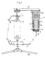
- a tower 1 that carries the power lines in a double circuit electrical transmission circuit typically has two set of three support arms 2,3 horizontally extending in opposite directions.
- An insulator 5,6 is carried near the end portion of each of the arms.
- the insulators are assembled from a plurality of suspended insulator pieces connected in series at are secured to the arms 2,3 by way of support member 4, respectively.
- Support member 7 are carried by the lower portion of the insulators 5, 6 to support an associated transmission lines 8,9 (which extend perpendicular to the cross section shown in Figure 2).
- Each circuit includes three phase transmission lines.
- an arrestor unit 11 is firmly suspended from the end of each right support arm 3.
- the arrestor units are supported by mounting adapters 10. Since the construction of each of the arrestor units may be the same, the construction of only one will be described in order to simplify the explanation.
- the arrestor unit 11 includes a pressure proof insulating cylinder 12 made of the reinforced plastic such as a fiber reinforced plastic.
- An arrestor element composed of a plurality of arrestor element segments 13 is accommodated in the cylinder 12.
- An insulating housing 14 is secured to the outer and inner peripheral surfaces of the cylinder 12 by means of a molded rubber.
- Each arrestor element segment 13 is in major part made of zinc oxide, which has a non-linear voltage-current characteristic.
- each arrestor element segment 13 is cylindrical in shape with a diameter of 4.5 cm and thickness of 2.0 cm.
- the reference voltage or critical operating voltage of the arrestor element 11 (at 1 ampere) is set to be at least 5.0 kv (peak value).
- eight arrestor elements 13 are stacked to obtain the predetermined desired length of arrestor elements 13.
- the rated voltage of an arrestor unit 11 of the described size and length is 40 kv (i.e. 69 kv/ ⁇ 3) and is suitable for a transmission line having a nominal voltage of 66 kv.
- the rated voltage essentially determining the length of the arrestor element is substantially eqaul to the norminal line to ground voltage E.
- the reference voltage is set to be larger than that of the voltage E.
- An arrestor unit 11 accommodating twelve arrestor element segments 13 has an outer diameter of 20 cm and a length of 46 cm. Such an arrestor unit 11 has a gross weight of approximately 10 kg.
- the rated voltage is set to be ⁇ 3 times the nominal line to ground voltage E. Therefore, the rated voltage is set to 69 kv which is equal to the maximum line voltage.
- Such a conventional arrestor unit requires 20 elements and has a diameter of 200 mm, a length of 63 cm and a gross weight of 14 kg.
- arrestor units in accordance with the present invention will of course vary with the nominal voltage of the associated line. Suitable arrestor sizes for various specific applications are set forth in Table I below. In this table the corresponding data for conventional arrestor units is also presented for ready comparison.
- An earth side discharge electrode 16 is secured to a line side electrode bracket 15 in the arrestor unit 11.
- a line side discharge electrode 15 is supported by the lower member 7 of the insulators 6.
- the tip of the electrode 17 is separated from the electrode 16 by a discharging gap G having a predetermined length. It is to be noted that the electrode 17 is formed in the shape of a short bar and extends substantially horizontally for holding its tip to be in inner side relating to the electrode 16.
- Arc rings 20, 22 are mounted on an electrode fitting to minimize damage due to the pressure release.
- Arc horns 18, 19 are mounted to the upper and lower support member 4, 7 respectively, so that the lightning induced cascading flashover on insulators 5, 6 is prevented.
- An arc horn gap Z is formed between the arc horns 18, 19 for avoiding flashover due to an inner abnormal voltage. More specifically, arc horn gap Z of a 66 kv transmission line is approximately 590 mm long and its 50% flashover voltage is approximately 375 kv.
- the discharging gap G formed between rod-rod electrodes is approximately 390 mm in length and its 50% flashover voltage is approximately 300 kv.
- the insulating level in arrestor unit 11 is remarkably smaller than that of the insulators 5, 6.
- 50% flashover voltage in a conventional arrestor unit having the same discharge gap G of 390 mm long is approximately 350 kv.
- this arrestor unit 11 can reduce the magnitude of 50% flashover voltage to 80% of that of the conventional art.
- the flashover voltage of the present arrestor unit 11 is reduced to a magnitude close to that of bias voltage of arrestor elements 13, so that the present arrestor unit 11 can obtain sufficient insulation coordination.
- the arrestor unit 11 which has an insulating level sufficiently lower than that of the insulator 6, allows the lightning surge current to pass therethrough to be discharged to the earth.
- the length of the discharge gap G is apt to be changed due to swinging of the insulator 6 is it is blown by wind. This result in the arrestor having an unstable insulating level.
- the reduced insulating level of the arrestor insures that the highest magnitude of the insulating level remains less than that of the insulators 5, 6 regardless of variations in the discharge gap G due to swing by winds within the allowable range.
- the lightning arrestor of the first embodiment is used both circuits of the double circuit transmission system. That is, each of the insulators 5, 6 has an associated lightning arrestor with sufficient insulating co-ordination ability to prevent the grounding faults. Therefore, the greater reliability of the arrestor is assured in this embodiment than in the first embodiment wherein only the single circuit 9 carries the arrestor.
- the present embodiment also provides the economical construction, because the arrestor is compact and very low priced in comparison with the conventional arrestor.
- the lightning arrestor used in the foregoing embodiments is coupled to single circuit transmission lines.
- the arrestor is mounted to every insulator, the number of grounding faults in the line is remarkably reduced. This leads the described lightning arrestor to be less outlay-spending than conventional arrestors in view of total cost including product cost, market cost, maintenance cost etc.
- the arrestor could be carried by a tension type tower in place of the suspension type tower.
Landscapes
- Engineering & Computer Science (AREA)
- Power Engineering (AREA)
- Insulators (AREA)
- Thermistors And Varistors (AREA)
Claims (6)
- Parafoudre sur une ligne de transmission comprenant une unité de parafoudre (11) comportant une pluralité d'éléments de parafoudre (13), ladite unité de parafoudre étant en série avec un intervalle de décharge aérien G, l'unité de parafoudre et l'intervalle de décharge aérien étant en parallèle à un isolateur (6) disposé entre une ligne d'alimentation en puissance et son bras d'organe de support,
caractérisé en ce que la pluralité des éléments de parafoudre est activée par une tension de référence supérieure à la tension nominale de ligne à la masse E de la ligne d'alimentation et inférieure à la surtension d'une phase de son en raison d'un défaut de masse d'une phase unique dans la ligne d'alimentation. - Parafoudre tel qu'énoncé dans la revendication 1, dans lequel l'électrode de décharge côté charge (17) est disposée de telle façon qu'une pointe de l'électrode (17) soit orientée vers un côté intérieur d'une électrode de décharge côté terre (16).
- Parafoure tel qu'énoncé dans la revendication 1 ou 2, dans lequel le parafoudre précité est relié à un circuit unique d'un système de transmission à circuit double.
- Parafoudre tel qu'énoncé dans la revendication 1 ou 2, dans lequel le parafoudre précité est relié aux deux circuits d'un système de transmission à circuit double.
- Système de transmission de puissance électrique comprenant un parafoudre sur une ligne de transmission, tel que défini dans une des revendications 1 à 4, dans lequel des lignes de transmission ont une tension nominale de ligne à la masse E et ledit parafoudre est disposé entre la charge et la terre des lignes de transmission en série avec un intervalle de décharge G, l'unité de parafoudre et l'intervalle de décharge étant en parallèle à un isolateur (6) qui supporte les lignes de transmission.
- Procédé pour faire fonctionner un système de transmission de puissance électrique, comprenant l'opération de prévoir un parafoudre sur une ligne de transmission, tel que défini dans une des revendications 1 à 4, monté entre la charge et la terre de ligne de transmission du système en série avec un intervalle de décharge G, l'unité de parafoudre et l'intervalle de décharge étant en parallèle à un isolateur (6) qui supporte les lignes de transmission dans lesquelles la pluralité d'éléments de parafoudre contenue dans l'unité de parafoudre est activée par une tension de référence supérieure à la tension nominale de ligne à la masse E de la ligne d'alimentation et inférieure à la surtension d'une phase de son en raison à un défaut de masse de phase unique dans la ligne d'alimentation.
Applications Claiming Priority (2)
| Application Number | Priority Date | Filing Date | Title |
|---|---|---|---|
| JP2134522A JPH0432114A (ja) | 1990-05-24 | 1990-05-24 | 避雷碍子装置 |
| JP134522/90 | 1990-05-24 |
Publications (2)
| Publication Number | Publication Date |
|---|---|
| EP0459727A1 EP0459727A1 (fr) | 1991-12-04 |
| EP0459727B1 true EP0459727B1 (fr) | 1996-03-20 |
Family
ID=15130296
Family Applications (1)
| Application Number | Title | Priority Date | Filing Date |
|---|---|---|---|
| EP91304748A Expired - Lifetime EP0459727B1 (fr) | 1990-05-24 | 1991-05-24 | Système dérivateur de surtensions |
Country Status (3)
| Country | Link |
|---|---|
| US (1) | US5172297A (fr) |
| EP (1) | EP0459727B1 (fr) |
| JP (1) | JPH0432114A (fr) |
Families Citing this family (14)
| Publication number | Priority date | Publication date | Assignee | Title |
|---|---|---|---|---|
| US6018453A (en) * | 1998-06-18 | 2000-01-25 | Cooper Industries, Inc. | Surge arrester protection system and method |
| US6625280B1 (en) | 1999-11-01 | 2003-09-23 | Avaya Technology Corp. | Balanced heat coil protector |
| CN2854890Y (zh) * | 2005-11-17 | 2007-01-03 | 郭玉章 | 电力输电线路综合防雷系统 |
| KR100893753B1 (ko) * | 2007-06-14 | 2009-04-17 | 전유철 | 전주용 피뢰기 설치구조 |
| CN101844685B (zh) * | 2010-05-25 | 2012-02-22 | 鞍山舒跃科技发展有限公司 | 排岩机用的直击雷防护装置 |
| US8711538B2 (en) * | 2010-10-06 | 2014-04-29 | Jonathan Jay Woodworth | Externally gapped line arrester |
| DE102011078333A1 (de) * | 2011-06-29 | 2013-01-03 | Siemens Aktiengesellschaft | Überspannungsableiter |
| US8922958B2 (en) | 2012-06-12 | 2014-12-30 | General Electric Company | Method and systems for discharging energy from an electrical fault |
| CN104715868B (zh) * | 2015-02-10 | 2017-01-18 | 王巨丰 | 一种防石墨炸弹破坏的绝缘子串 |
| CN105116282B (zh) * | 2015-07-03 | 2018-04-06 | 国网辽宁省电力有限公司抚顺供电公司 | 一种电缆故障测试遥控放电球隙装置 |
| WO2021004244A1 (fr) * | 2019-07-08 | 2021-01-14 | 陕西和硕电气有限公司 | Parafoudre anti-chute à déclenchement automatique et dispositif combiné de protection contre la foudre à fusibles intégrés |
| JP7277330B2 (ja) * | 2019-09-25 | 2023-05-18 | 西日本旅客鉄道株式会社 | 碍子用アークホーン |
| CN111666662B (zh) * | 2020-05-22 | 2023-03-21 | 长沙理工大学 | 一种10kV架空线路并联间隙的单相同线安装方法 |
| DE102024108045B4 (de) * | 2024-03-20 | 2026-04-16 | TRIDELTA Meidensha GmbH | Überspannungsschutzvorrichtungen für eine Hochspannungsleitung |
Family Cites Families (7)
| Publication number | Priority date | Publication date | Assignee | Title |
|---|---|---|---|---|
| US3963965A (en) * | 1974-10-22 | 1976-06-15 | Westinghouse Electric Corporation | Surge arrester construction |
| SE397026B (sv) * | 1975-03-18 | 1977-10-10 | Asea Ab | Ventilavledaranordning |
| US4467387A (en) * | 1982-09-30 | 1984-08-21 | General Electric Company | Combination strut insulator and lightning arrester |
| DE3478979D1 (en) * | 1983-03-03 | 1989-08-17 | Schaff Jean Paul | Device for protecting overhead electroconducting lines against lightning |
| JPS60262312A (ja) * | 1984-06-09 | 1985-12-25 | 東京電力株式会社 | 送電線用限流ホ−ン装置 |
| JPS61112521A (ja) * | 1984-11-05 | 1986-05-30 | 中国電力株式会社 | 送電線保護システム |
| EP0183873A1 (fr) * | 1984-12-07 | 1986-06-11 | L 'Electricité Industrielle Belge S.A. | Dérivateur de surtensions pour une ligne aérienne à courant continu |
-
1990
- 1990-05-24 JP JP2134522A patent/JPH0432114A/ja active Pending
-
1991
- 1991-05-23 US US07/704,507 patent/US5172297A/en not_active Expired - Fee Related
- 1991-05-24 EP EP91304748A patent/EP0459727B1/fr not_active Expired - Lifetime
Non-Patent Citations (1)
| Title |
|---|
| HIGH VOLTAGE MEASUREMENT, Testing and Design, T.J.Gallagher and A.J. Pearmain, publ. John Wiley and Sons, Chichester, 1983, pp. 15-17 * |
Also Published As
| Publication number | Publication date |
|---|---|
| EP0459727A1 (fr) | 1991-12-04 |
| US5172297A (en) | 1992-12-15 |
| JPH0432114A (ja) | 1992-02-04 |
Similar Documents
| Publication | Publication Date | Title |
|---|---|---|
| EP0459727B1 (fr) | Système dérivateur de surtensions | |
| CA1144594A (fr) | Fusible de borne et parafoudre pour transformateur haute tension | |
| Ishida et al. | Development of a 500 kV transmission line arrester and its characteristics | |
| US5426555A (en) | Surge arrester arrangement | |
| US6002571A (en) | Lightning arrester assembly for an overhead electricity line with a device for flagging an arrester malfunction | |
| JP7222079B2 (ja) | 外部ギャップ付き避雷器 | |
| JP2698445B2 (ja) | 送電線用懸垂型避雷碍子装置 | |
| US4754363A (en) | Metal-encapsulated gas-insulated high-voltage installation with an overvoltage arrester | |
| US4736272A (en) | Current-limiting arcing horn | |
| US4774622A (en) | Connecting apparatus for lightning arresters for overhead transmission lines | |
| EP0655814A1 (fr) | Dérivateur de surtensions à bras de support isolateur | |
| JP2561762B2 (ja) | 並列型避雷碍子装置 | |
| EP0004348B1 (fr) | Dispositif parafoudre pour ligne de transmission d'énergie | |
| JPH06113434A (ja) | 相間スペーサ | |
| KR102697228B1 (ko) | 서지 어레스팅 컷아우트스위치 | |
| EP1138050B1 (fr) | Limiteur de surtension, monte sur une ligne de transmission, avec un dispositif de stabilisation | |
| JPH0367291B2 (fr) | ||
| JP2535501B2 (ja) | 非直線抵抗素子付オ−プンカツトアウト | |
| JP2941974B2 (ja) | 二回線送電線路における避雷碍子装置 | |
| JPH04272621A (ja) | 一回線送電線路における避雷碍子装置 | |
| JP2564324B2 (ja) | 耐雷ホーン碍子装置 | |
| JPH0134505Y2 (fr) | ||
| JPS62117221A (ja) | 架空送電線用避雷碍子装置 | |
| JPH0242037Y2 (fr) | ||
| JPH06209514A (ja) | 避雷型相間スペーサ |
Legal Events
| Date | Code | Title | Description |
|---|---|---|---|
| PUAI | Public reference made under article 153(3) epc to a published international application that has entered the european phase |
Free format text: ORIGINAL CODE: 0009012 |
|
| AK | Designated contracting states |
Kind code of ref document: A1 Designated state(s): FR GB |
|
| 17P | Request for examination filed |
Effective date: 19920313 |
|
| 17Q | First examination report despatched |
Effective date: 19931008 |
|
| GRAH | Despatch of communication of intention to grant a patent |
Free format text: ORIGINAL CODE: EPIDOS IGRA |
|
| GRAA | (expected) grant |
Free format text: ORIGINAL CODE: 0009210 |
|
| AK | Designated contracting states |
Kind code of ref document: B1 Designated state(s): FR GB |
|
| ET | Fr: translation filed | ||
| PLBE | No opposition filed within time limit |
Free format text: ORIGINAL CODE: 0009261 |
|
| STAA | Information on the status of an ep patent application or granted ep patent |
Free format text: STATUS: NO OPPOSITION FILED WITHIN TIME LIMIT |
|
| 26N | No opposition filed | ||
| PGFP | Annual fee paid to national office [announced via postgrant information from national office to epo] |
Ref country code: GB Payment date: 19980514 Year of fee payment: 8 Ref country code: FR Payment date: 19980514 Year of fee payment: 8 |
|
| PG25 | Lapsed in a contracting state [announced via postgrant information from national office to epo] |
Ref country code: GB Free format text: LAPSE BECAUSE OF NON-PAYMENT OF DUE FEES Effective date: 19990524 |
|
| GBPC | Gb: european patent ceased through non-payment of renewal fee |
Effective date: 19990524 |
|
| PG25 | Lapsed in a contracting state [announced via postgrant information from national office to epo] |
Ref country code: FR Free format text: LAPSE BECAUSE OF NON-PAYMENT OF DUE FEES Effective date: 20000131 |
|
| REG | Reference to a national code |
Ref country code: FR Ref legal event code: ST |