EP0458302A2 - Relais à télécommande - Google Patents
Relais à télécommande Download PDFInfo
- Publication number
- EP0458302A2 EP0458302A2 EP91108274A EP91108274A EP0458302A2 EP 0458302 A2 EP0458302 A2 EP 0458302A2 EP 91108274 A EP91108274 A EP 91108274A EP 91108274 A EP91108274 A EP 91108274A EP 0458302 A2 EP0458302 A2 EP 0458302A2
- Authority
- EP
- European Patent Office
- Prior art keywords
- plunger
- coil
- switch
- micro
- stroke
- Prior art date
- Legal status (The legal status is an assumption and is not a legal conclusion. Google has not performed a legal analysis and makes no representation as to the accuracy of the status listed.)
- Granted
Links
Images


Classifications
-
- H—ELECTRICITY
- H01—ELECTRIC ELEMENTS
- H01H—ELECTRIC SWITCHES; RELAYS; SELECTORS; EMERGENCY PROTECTIVE DEVICES
- H01H47/00—Circuit arrangements not adapted to a particular application of the relay and designed to obtain desired operating characteristics or to provide energising current
- H01H47/22—Circuit arrangements not adapted to a particular application of the relay and designed to obtain desired operating characteristics or to provide energising current for supplying energising current for relay coil
- H01H47/226—Circuit arrangements not adapted to a particular application of the relay and designed to obtain desired operating characteristics or to provide energising current for supplying energising current for relay coil for bistable relays
-
- H—ELECTRICITY
- H01—ELECTRIC ELEMENTS
- H01H—ELECTRIC SWITCHES; RELAYS; SELECTORS; EMERGENCY PROTECTIVE DEVICES
- H01H51/00—Electromagnetic relays
-
- H—ELECTRICITY
- H01—ELECTRIC ELEMENTS
- H01H—ELECTRIC SWITCHES; RELAYS; SELECTORS; EMERGENCY PROTECTIVE DEVICES
- H01H51/00—Electromagnetic relays
- H01H51/22—Polarised relays
-
- H—ELECTRICITY
- H01—ELECTRIC ELEMENTS
- H01H—ELECTRIC SWITCHES; RELAYS; SELECTORS; EMERGENCY PROTECTIVE DEVICES
- H01H51/00—Electromagnetic relays
- H01H51/22—Polarised relays
- H01H51/2209—Polarised relays with rectilinearly movable armature
Definitions
- Fig. 11 shows a remotely-controlled relay described in the same inventor's copending U.S. Patent Application based on Japanese Patent Application No. 2-133027 which has the same filing date in Japan as that of the present invention.
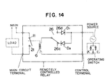
- Fig. 14 shows the electrical circuit of the remotely controlled relay shown in Fig. 11.
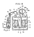
- Fig. 12 shows the relevant portion of the remotely controlled relay when a main circuit is open.
- the operating lever 28 drives at its abutment 28c the actuator 26a of a micro-switch 26 so that the micro-switch 26 is switched to have a movable contact thereof in contact with 26d.
- the plunger 5 further advances upwards with the aid of inertia until it is securely attracted by the upper end of a yoke 8, causing the contacts 11 and 21 of the main circuit to close.
- Fig. 13 shows a relevant portion of a remotely controlled relay when a main circuit is closed.
- an operating switch When an operating switch is switched to the position A in Fig. 14, the operating current flows through a diode D1 into the coil 6 to drive the plunger 5 in the direction of the arrow E in Fig. 13.
- the operating lever 28 rotates counterclockwise.
- the plunger 5 reaches the middle of its stroke, the operating lever 28 drives at the abutment 28c the actuator 26a so that the micro-switch 26 is switched to have a movable contact thereof in contact with 26c.
- the plunger 5 further advances upward with the aid of inertia until it is securely attracted by the bottom of the yoke 8, causing the contacts 11 and 21 of the main circuit to open.
- this type of bistable polar electromagnet device has a micro-switch that is switched at the middle of the plunger stroke.
- the attracting force of magnetized yoke 8 that attracts the plunger becomes increasingly stronger as the plunger becomes closer to the upper end or bottom of the yoke 8.
- the manufacture of the relay is not easy.
- a high current is run through the coil 6 so that the plunger 5 is driven by a large magnetic force to pass through the middle of the stroke with a large inertia.
- An object of the invention is to provide a remotely-controlled relay that requires no critical, precise adjustment of the position of micro-switch relative to the that of plunger in its stroke such that the micro-switch is switched from one contact to another to change the direction of driving current through the relay coil.
- Another object of the invention is to provide a remotely controlled relay that requires only a small current for magnetising the relay coil to drive the plunger.
- a remotely controlled relay has two micro-switches driven by the plunger of a bistable polar electromagnet device.
- a current is supplied to the coil of the electromagnet device from an external power source to magnetize the plunger so that the plunger is moved through a stroke between a first position and a second position.
- a first micro-switch is closed to energize the coil in a first direction until the plunger passes through the middle of the stroke.
- a second micro-switch is closed to energize the coil in a second direction until the plunger passes through the middle of the stroke.
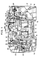
- Fig. 1 is a general side view of a remotely-controlled relay according to the invention.
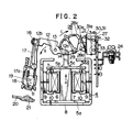
- Fig. 2 is a side view of a relevant portion of Fig. 1.
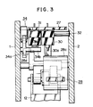
- Fig. 3 is a top view of Fig. 2 and
- Fig. 4 is a side view of a relevant portion of Fig. 1.
- a housing consists of a base 1 and a cover 2 which are riveted together at four locations by rivets 3.
- the housing has grooves 1a into which mounting angles are inserted, projections by which the relay is mounted on DIN rails, and an aperture 1c at the top of the housing.
- An electromagnet device 4 is of a bistable polar type having two stable positions where a plunger 5 is securely attracted by a magnet, and is provided in the middle of the base 1. As shown in Figs. 1 and 2, a coil 6 is wound about a bobbin 7, shown hatched, through which the plunger 5 slidably extends.
- the plunger 5 acts as an armature having a top end 5b and a bottom end 5b, attracted by a yoke 8 magnetized by a permanent magnet 9.
- the bobbin 7 and the plunger 5 are housed in a first yoke 8, and the plunger 5 extends at a distal end thereof outwardly of the yoke 8 through an aperture 8a.
- a pair of permanent magnets 9 On the inner wall of the first yoke 8 is provided a pair of permanent magnets 9.
- a second yoke 10 having a generally U-shaped cross section is mounted between the permanent magnet 9 and bobbin 7 such that the yoke 10 abuts the magnet 9 as well as holds the bobbin 7.
- a link 12 is pivotally mounted on the base 1 by means of a pin 13, and is pivotally connected at one end 12a thereof through a pin 14 to the plunger tip end 5c and at the other end 12b to one end of a movable-contact assembly 15 through a pin 16.
- the movable-contact assembly 15 is provided with an insulator 17 having a groove 17a into which a movable piece 18 engages in sliding relation.
- the movable piece 18 has a contact 11 which is electrically connected with a terminal 23 of the main circuit by means of a shunt 22.
- the contact 11 is provided with a compression spring 19 that urges the contact 11 against a fixed contact 21 on a terminal 20 of the main circuit.
- the movable-contact assembly 15 and the contacts 11 and 21 forms a main-circuit-opening and closing assembly.
- a pin 17b mounted to the insulator 17 loosely engages and guided by a groove(not shown) in the base 1 and a groove(not shown) in the cover 2 so that the movable-contact assembly 15 is operatively driven by the plunger 5 to close and open the contacts 11 and 14.
- the operating lever 28 is pivotally mounted to the base 1 by means of a pin 29 and is pivotally connected to the tip end 5c by means of a pin 14.
- the operating lever 28 pivots about the pin 29 when the plunger moves up and down.
- the operating lever 28 has a handle 28a facing the aperture 1c for manually operating the lever 28.
- On both sides of the handle 28a is provided a display 28c that indicates ON and OFF states of the contacts 11 and 14.
- Micro-switches 30 and 31 each have two holes therein through which pins 32 and 33 extends.
- the pins 32 and 33 are supported by the base 1 and cover 2.
- the two micro-switches are properly aligned their relative positions by the aid of the pins 32 and 33.
- To the pin 33 is pivotally connected an actuating lever 34 driven into pivotal motion by a projection 28d of the operating lever 28, which engages the bifurcation 34a of the actuating lever 34.
- a projection 34b engages the actuator 31a of the micro-switch 31 to open and close the switch 31 while the abutment 28c engaging the actuator 30a of the micro-switch 30.
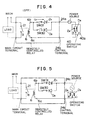
- Fig. 4 shows an electrical circuit of the remotely-controlled relay in Fig. 1.
- One end 6a of the coil 6 is connected to a control terminal 24b and the other 6b to the common terminals of the micro-switches 30 and 31.
- the contact of the micro-switch 30 is connected with the cathode of a diode D2, and the contact of the micro-switch SW31 to the anode of a diode D1.
- the cathode of D1 and the anode of D2 are connected together to a control terminals 24a.
- Between the terminals 24a and 24b is connected an external series connection of a power source and an operating switch 40 that includes diodes D3 and D4 and a normally open single-pole-double-throw switch 40a.
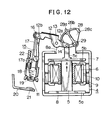
- Fig. 10 illustrates the relationship between the movement of plunger and the timing at which the micro-switch is switched.
- the bottom end 5a is at the bottom of the yoke 8, securely attracted by the yoke 8.
- an ON-operating current flows in the direction of the arrow C2 through the loop of D3 -- contact J -- coil 6 -- SW 31 -- D1 -- power source.
- the coil 6 magnetizes the plunger 5 in a direction opposite to the magnetic poles shown in Fig. 2, so that the plunger 5 repels the S pole of the bottom of yoke 8 and is driven in the direction of A in Fig. 2 to move to a point P in Fig.
- Fig. 6 shows the positional relationship between the relevant mechanical parts and Fig. 5 shows the electrical circuit of Fig. 6. It should be noted that the micro-switches 30 and 31 are both closed. In Fig. 6, the plunger 5 is advancing in the direction A.
- the micro-switches 30 and 31 are both closed while the plunger 5 is between points P and Q, no current flows through the micro-switch 30.
- the operating current continues to flow in the direction of C2 through the micro-switch 31 so as to drive the plunger 5 in the direction of A.
- the plunger 5 remains driven until it reaches point Q past the middle point M of the plunger stroke.
- the actuating lever 34 acts on the actuator 31a to open the micro-switch 31.
- the operating-current path changes from the loop of D3 -- contact J -- coil 6 -- SW31 -- D1 -- power source to the loop of D3 -- contact J -- coil 6 -- SW30 -- D2 -- power source, so that even if the operator continues to depress the switch 40a to side J, no current flows in the coil 6.
- the coil 6 no longer produces a force to drive the plunger 5.
- the plunger 5 is now sufficiently close to the upper end of yoke 8 to be attracted towards the upper end and stops at the position shown in Fig. 7 closing the contacts 11 and 14.
- Fig. 7 is a side view showing a remotely-controlled relay when the main circuit is closed.
- Fig. 8 is a top view of Fig. 7. As shown in Fig. 7, the top end 5b is at the upper end of the yoke 8, securely attracted by the yoke 8.
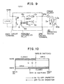
- Fig. 9 when the switch 40a is switched to the position K, an OFF-operating current flows in the direction of the arrow C1 through the loop of D2 -- SW30 -- coil 6 -- contact K -- D4 -- power source.
- the coil 6 magnetizes the plunger 5 to polarities opposite to those shown in Fig. 2, so that the plunger 5 repels the S pole of the upper end of yoke 8 and is driven in the direction of E to move to a point Q in Fig.
- Fig. 6 shows the positional relationship between the relevant mechanical parts and Fig. 5 shows the electrical circuit of Fig. 6. It should be noted that the micro-switches 30 and 31 are both closed. In Fig. 6, the plunger is advancing in the direction of E. Although the micro-switches are both closed while the plunger 5 is between points P and Q, no current flows through the micro-switch 31.
- the operating current continues to flow in the direction of C1 through the micro-switch 30 so as to drive the plunger in the direction of E.
- the plunger 5 remains driven until it reaches point P past the middle point M of the plunger stroke.
- the actuating lever 34 acts on the actuator 30a to open the micro-switch 30.
- the operating-current path changes from the loop of D2 --SW30 -- coil 6 -- contact K -- D4 -- power source to a loop of D1 -- SW31 coil 6 -- contact K -- D4 -- power source, so that even if the operator continues to depress the switch 40a to the side K, no current flows in the coil 6.
- the coil 6 no longer produces a force to drive the plunger 5. Since the plunger is now sufficiently close to the bottom of yoke 8, the plunger is attracted towards the bottom and then stops at the position shown in Fig. 7 opening the contacts 11 and 14.
Landscapes
- Physics & Mathematics (AREA)
- Electromagnetism (AREA)
- Relay Circuits (AREA)
- Keying Circuit Devices (AREA)
- Mechanisms For Operating Contacts (AREA)
Applications Claiming Priority (2)
| Application Number | Priority Date | Filing Date | Title |
|---|---|---|---|
| JP2133026A JPH0428134A (ja) | 1990-05-23 | 1990-05-23 | リモコンリレー |
| JP133026/90 | 1990-05-23 |
Publications (3)
| Publication Number | Publication Date |
|---|---|
| EP0458302A2 true EP0458302A2 (fr) | 1991-11-27 |
| EP0458302A3 EP0458302A3 (en) | 1992-09-23 |
| EP0458302B1 EP0458302B1 (fr) | 1996-04-03 |
Family
ID=15095064
Family Applications (1)
| Application Number | Title | Priority Date | Filing Date |
|---|---|---|---|
| EP91108274A Expired - Lifetime EP0458302B1 (fr) | 1990-05-23 | 1991-05-22 | Relais à télécommande |
Country Status (6)
| Country | Link |
|---|---|
| US (1) | US5172086A (fr) |
| EP (1) | EP0458302B1 (fr) |
| JP (1) | JPH0428134A (fr) |
| KR (1) | KR940007432B1 (fr) |
| DE (1) | DE69118437T2 (fr) |
| ZA (1) | ZA913911B (fr) |
Cited By (2)
| Publication number | Priority date | Publication date | Assignee | Title |
|---|---|---|---|---|
| EP0544928A1 (fr) * | 1991-11-29 | 1993-06-09 | Mitsubishi Denki Kabushiki Kaisha | Relais à télécommande |
| US6009615A (en) * | 1993-09-11 | 2000-01-04 | Brian Mckean Associates Limited | Method of manufacturing a bistable magnetic actuator |
Families Citing this family (4)
| Publication number | Priority date | Publication date | Assignee | Title |
|---|---|---|---|---|
| US6724284B2 (en) * | 2001-02-02 | 2004-04-20 | Eaton Corporation | Circuit breaker |
| US7342474B2 (en) * | 2004-03-29 | 2008-03-11 | General Electric Company | Circuit breaker configured to be remotely operated |
| JP6312021B2 (ja) * | 2014-01-30 | 2018-04-18 | パナソニックIpマネジメント株式会社 | リモコンリレー |
| US10679811B2 (en) * | 2017-09-12 | 2020-06-09 | Littelfuse, Inc. | Wide operating range relay controller system |
Family Cites Families (8)
| Publication number | Priority date | Publication date | Assignee | Title |
|---|---|---|---|---|
| US3377519A (en) * | 1963-12-26 | 1968-04-09 | Allen Bradley Co | Magnetically latched switch |
| USRE32882E (en) * | 1982-01-01 | 1989-03-07 | Matsushita Electric Works, Ltd. | Remote control system circuit breaker |
| JPS58131636A (ja) * | 1982-01-29 | 1983-08-05 | 松下電工株式会社 | リモ−トコントロ−ル式回路しや断器 |
| DE3576428D1 (de) * | 1984-12-24 | 1990-04-12 | Matsushita Electric Works Ltd | Fernsteuerbares relais. |
| US4774484A (en) * | 1985-04-09 | 1988-09-27 | Square D Company | Auxiliary electrical contact for electromagnetic contactor |
| US4623859A (en) * | 1985-08-13 | 1986-11-18 | Square D Company | Remote control circuit breaker |
| JP2538991B2 (ja) * | 1988-06-09 | 1996-10-02 | 松下電工株式会社 | リモ―トコントロ―ル式回路しゃ断器 |
| KR920003958B1 (ko) * | 1988-10-06 | 1992-05-18 | 미쓰비시전기 주식회사 | 원격조작식 회로차단기 |
-
1990
- 1990-05-23 JP JP2133026A patent/JPH0428134A/ja active Pending
-
1991
- 1991-04-19 KR KR1019910006248A patent/KR940007432B1/ko not_active Expired - Fee Related
- 1991-05-22 EP EP91108274A patent/EP0458302B1/fr not_active Expired - Lifetime
- 1991-05-22 DE DE69118437T patent/DE69118437T2/de not_active Expired - Fee Related
- 1991-05-22 US US07/704,086 patent/US5172086A/en not_active Expired - Fee Related
- 1991-05-23 ZA ZA913911A patent/ZA913911B/xx unknown
Cited By (3)
| Publication number | Priority date | Publication date | Assignee | Title |
|---|---|---|---|---|
| EP0544928A1 (fr) * | 1991-11-29 | 1993-06-09 | Mitsubishi Denki Kabushiki Kaisha | Relais à télécommande |
| US5250920A (en) * | 1991-11-29 | 1993-10-05 | Mitsubishi Denki Kabushiki Kaisha | Remote controlled relay |
| US6009615A (en) * | 1993-09-11 | 2000-01-04 | Brian Mckean Associates Limited | Method of manufacturing a bistable magnetic actuator |
Also Published As
| Publication number | Publication date |
|---|---|
| US5172086A (en) | 1992-12-15 |
| EP0458302A3 (en) | 1992-09-23 |
| ZA913911B (en) | 1992-02-26 |
| KR910020774A (ko) | 1991-12-20 |
| KR940007432B1 (ko) | 1994-08-18 |
| EP0458302B1 (fr) | 1996-04-03 |
| DE69118437D1 (de) | 1996-05-09 |
| JPH0428134A (ja) | 1992-01-30 |
| DE69118437T2 (de) | 1996-08-08 |
Similar Documents
| Publication | Publication Date | Title |
|---|---|---|
| US5227750A (en) | Solenoid operated switching device | |
| US3388353A (en) | Electrical contactor having main circuit control contacts and auxiliary control contacts interconnected to be actuated from a common electromagnetic actuator | |
| US4855698A (en) | Protective switching apparatus with remotely controlled opening and closing of the contacts | |
| EP0148745B1 (fr) | Disjoncteur sous boîtier moulé avec un solénoide unique de commande d'un mouvement rectiligne du levier de commande | |
| US5172086A (en) | Remotely controlled relay | |
| US5200723A (en) | Remotely-controlled relay | |
| KR102374581B1 (ko) | 수동 액츄에이터를 구비한 고전압 래칭 릴레이 | |
| US5181001A (en) | Remotely-controlled relay | |
| CN110556269B (zh) | 电磁继电器 | |
| US5248951A (en) | Remote controlled relay | |
| US3611219A (en) | Electric snap switch | |
| US4521757A (en) | High speed electromagnetic mechanical switch | |
| JP2530990Y2 (ja) | リモコンリレー | |
| KR940003718Y1 (ko) | 리모콘릴레이 | |
| CN210120089U (zh) | 一种可断开闭合电路的电表连接结构及包含其的电能表 | |
| JP4354628B2 (ja) | リモコンリレー | |
| JPH056637U (ja) | リモコンリレー | |
| JP3151318B2 (ja) | 複数極を有するリモコンリレーの連動レバーの軸構造 | |
| JPH0428131A (ja) | リモコンリレー | |
| JP3151319B2 (ja) | 2極型リモコンリレー | |
| JPH065184A (ja) | リモコンリレー | |
| JPH05109525A (ja) | 電磁石装置 | |
| CN113574625A (zh) | 电子开关 | |
| JPH0574305A (ja) | リモコンリレー | |
| KR890004968B1 (ko) | 유극 릴레이 |
Legal Events
| Date | Code | Title | Description |
|---|---|---|---|
| PUAI | Public reference made under article 153(3) epc to a published international application that has entered the european phase |
Free format text: ORIGINAL CODE: 0009012 |
|
| AK | Designated contracting states |
Kind code of ref document: A2 Designated state(s): CH DE FR GB IT LI |
|
| PUAL | Search report despatched |
Free format text: ORIGINAL CODE: 0009013 |
|
| AK | Designated contracting states |
Kind code of ref document: A3 Designated state(s): CH DE FR GB IT LI |
|
| 17P | Request for examination filed |
Effective date: 19921014 |
|
| 17Q | First examination report despatched |
Effective date: 19940414 |
|
| GRAA | (expected) grant |
Free format text: ORIGINAL CODE: 0009210 |
|
| AK | Designated contracting states |
Kind code of ref document: B1 Designated state(s): CH DE FR GB IT LI |
|
| REG | Reference to a national code |
Ref country code: CH Ref legal event code: NV Representative=s name: BOVARD AG PATENTANWAELTE |
|
| REF | Corresponds to: |
Ref document number: 69118437 Country of ref document: DE Date of ref document: 19960509 |
|
| ET | Fr: translation filed | ||
| ITF | It: translation for a ep patent filed | ||
| GRAH | Despatch of communication of intention to grant a patent |
Free format text: ORIGINAL CODE: EPIDOS IGRA |
|
| PLBE | No opposition filed within time limit |
Free format text: ORIGINAL CODE: 0009261 |
|
| STAA | Information on the status of an ep patent application or granted ep patent |
Free format text: STATUS: NO OPPOSITION FILED WITHIN TIME LIMIT |
|
| 26N | No opposition filed | ||
| PGFP | Annual fee paid to national office [announced via postgrant information from national office to epo] |
Ref country code: FR Payment date: 19980511 Year of fee payment: 8 |
|
| PGFP | Annual fee paid to national office [announced via postgrant information from national office to epo] |
Ref country code: GB Payment date: 19980513 Year of fee payment: 8 |
|
| PGFP | Annual fee paid to national office [announced via postgrant information from national office to epo] |
Ref country code: DE Payment date: 19980529 Year of fee payment: 8 |
|
| PGFP | Annual fee paid to national office [announced via postgrant information from national office to epo] |
Ref country code: CH Payment date: 19980610 Year of fee payment: 8 |
|
| PG25 | Lapsed in a contracting state [announced via postgrant information from national office to epo] |
Ref country code: GB Free format text: LAPSE BECAUSE OF NON-PAYMENT OF DUE FEES Effective date: 19990522 |
|
| PG25 | Lapsed in a contracting state [announced via postgrant information from national office to epo] |
Ref country code: LI Free format text: LAPSE BECAUSE OF NON-PAYMENT OF DUE FEES Effective date: 19990531 Ref country code: CH Free format text: LAPSE BECAUSE OF NON-PAYMENT OF DUE FEES Effective date: 19990531 |
|
| REG | Reference to a national code |
Ref country code: CH Ref legal event code: PL |
|
| GBPC | Gb: european patent ceased through non-payment of renewal fee |
Effective date: 19990522 |
|
| PG25 | Lapsed in a contracting state [announced via postgrant information from national office to epo] |
Ref country code: FR Free format text: LAPSE BECAUSE OF NON-PAYMENT OF DUE FEES Effective date: 20000131 |
|
| PG25 | Lapsed in a contracting state [announced via postgrant information from national office to epo] |
Ref country code: DE Free format text: LAPSE BECAUSE OF NON-PAYMENT OF DUE FEES Effective date: 20000301 |
|
| REG | Reference to a national code |
Ref country code: FR Ref legal event code: ST |
|
| PG25 | Lapsed in a contracting state [announced via postgrant information from national office to epo] |
Ref country code: IT Free format text: LAPSE BECAUSE OF NON-PAYMENT OF DUE FEES;WARNING: LAPSES OF ITALIAN PATENTS WITH EFFECTIVE DATE BEFORE 2007 MAY HAVE OCCURRED AT ANY TIME BEFORE 2007. THE CORRECT EFFECTIVE DATE MAY BE DIFFERENT FROM THE ONE RECORDED. Effective date: 20050522 |