EP0458139A2 - Werkzeugblock für das Strangpressen einer Kabelführungsvorrichtung - Google Patents
Werkzeugblock für das Strangpressen einer Kabelführungsvorrichtung Download PDFInfo
- Publication number
- EP0458139A2 EP0458139A2 EP91107565A EP91107565A EP0458139A2 EP 0458139 A2 EP0458139 A2 EP 0458139A2 EP 91107565 A EP91107565 A EP 91107565A EP 91107565 A EP91107565 A EP 91107565A EP 0458139 A2 EP0458139 A2 EP 0458139A2
- Authority
- EP
- European Patent Office
- Prior art keywords
- tool
- sliding
- cable guide
- extrusion
- rib
- Prior art date
- Legal status (The legal status is an assumption and is not a legal conclusion. Google has not performed a legal analysis and makes no representation as to the accuracy of the status listed.)
- Granted
Links
- 238000001125 extrusion Methods 0.000 title claims abstract description 25
- 238000004519 manufacturing process Methods 0.000 claims description 5
- 229920001169 thermoplastic Polymers 0.000 claims description 2
- 239000004416 thermosoftening plastic Substances 0.000 claims description 2
- 239000012815 thermoplastic material Substances 0.000 abstract description 2
- 238000010276 construction Methods 0.000 description 1
- 239000007787 solid Substances 0.000 description 1
Images


Classifications
-
- G—PHYSICS
- G02—OPTICS
- G02B—OPTICAL ELEMENTS, SYSTEMS OR APPARATUS
- G02B6/00—Light guides; Structural details of arrangements comprising light guides and other optical elements, e.g. couplings
- G02B6/44—Mechanical structures for providing tensile strength and external protection for fibres, e.g. optical transmission cables
- G02B6/4439—Auxiliary devices
- G02B6/4459—Ducts; Conduits; Hollow tubes for air blown fibres
-
- B—PERFORMING OPERATIONS; TRANSPORTING
- B29—WORKING OF PLASTICS; WORKING OF SUBSTANCES IN A PLASTIC STATE IN GENERAL
- B29C—SHAPING OR JOINING OF PLASTICS; SHAPING OF MATERIAL IN A PLASTIC STATE, NOT OTHERWISE PROVIDED FOR; AFTER-TREATMENT OF THE SHAPED PRODUCTS, e.g. REPAIRING
- B29C48/00—Extrusion moulding, i.e. expressing the moulding material through a die or nozzle which imparts the desired form; Apparatus therefor
- B29C48/03—Extrusion moulding, i.e. expressing the moulding material through a die or nozzle which imparts the desired form; Apparatus therefor characterised by the shape of the extruded material at extrusion
- B29C48/06—Rod-shaped
-
- B—PERFORMING OPERATIONS; TRANSPORTING
- B29—WORKING OF PLASTICS; WORKING OF SUBSTANCES IN A PLASTIC STATE IN GENERAL
- B29C—SHAPING OR JOINING OF PLASTICS; SHAPING OF MATERIAL IN A PLASTIC STATE, NOT OTHERWISE PROVIDED FOR; AFTER-TREATMENT OF THE SHAPED PRODUCTS, e.g. REPAIRING
- B29C48/00—Extrusion moulding, i.e. expressing the moulding material through a die or nozzle which imparts the desired form; Apparatus therefor
- B29C48/03—Extrusion moulding, i.e. expressing the moulding material through a die or nozzle which imparts the desired form; Apparatus therefor characterised by the shape of the extruded material at extrusion
- B29C48/09—Articles with cross-sections having partially or fully enclosed cavities, e.g. pipes or channels
- B29C48/11—Articles with cross-sections having partially or fully enclosed cavities, e.g. pipes or channels comprising two or more partially or fully enclosed cavities, e.g. honeycomb-shaped
-
- B—PERFORMING OPERATIONS; TRANSPORTING
- B29—WORKING OF PLASTICS; WORKING OF SUBSTANCES IN A PLASTIC STATE IN GENERAL
- B29C—SHAPING OR JOINING OF PLASTICS; SHAPING OF MATERIAL IN A PLASTIC STATE, NOT OTHERWISE PROVIDED FOR; AFTER-TREATMENT OF THE SHAPED PRODUCTS, e.g. REPAIRING
- B29C48/00—Extrusion moulding, i.e. expressing the moulding material through a die or nozzle which imparts the desired form; Apparatus therefor
- B29C48/03—Extrusion moulding, i.e. expressing the moulding material through a die or nozzle which imparts the desired form; Apparatus therefor characterised by the shape of the extruded material at extrusion
- B29C48/12—Articles with an irregular circumference when viewed in cross-section, e.g. window profiles
-
- B—PERFORMING OPERATIONS; TRANSPORTING
- B29—WORKING OF PLASTICS; WORKING OF SUBSTANCES IN A PLASTIC STATE IN GENERAL
- B29C—SHAPING OR JOINING OF PLASTICS; SHAPING OF MATERIAL IN A PLASTIC STATE, NOT OTHERWISE PROVIDED FOR; AFTER-TREATMENT OF THE SHAPED PRODUCTS, e.g. REPAIRING
- B29C48/00—Extrusion moulding, i.e. expressing the moulding material through a die or nozzle which imparts the desired form; Apparatus therefor
- B29C48/25—Component parts, details or accessories; Auxiliary operations
- B29C48/30—Extrusion nozzles or dies
- B29C48/32—Extrusion nozzles or dies with annular openings, e.g. for forming tubular articles
- B29C48/33—Extrusion nozzles or dies with annular openings, e.g. for forming tubular articles with parts rotatable relative to each other
-
- B—PERFORMING OPERATIONS; TRANSPORTING
- B29—WORKING OF PLASTICS; WORKING OF SUBSTANCES IN A PLASTIC STATE IN GENERAL
- B29C—SHAPING OR JOINING OF PLASTICS; SHAPING OF MATERIAL IN A PLASTIC STATE, NOT OTHERWISE PROVIDED FOR; AFTER-TREATMENT OF THE SHAPED PRODUCTS, e.g. REPAIRING
- B29C48/00—Extrusion moulding, i.e. expressing the moulding material through a die or nozzle which imparts the desired form; Apparatus therefor
- B29C48/25—Component parts, details or accessories; Auxiliary operations
- B29C48/30—Extrusion nozzles or dies
- B29C48/345—Extrusion nozzles comprising two or more adjacently arranged ports, for simultaneously extruding multiple strands, e.g. for pelletising
-
- B—PERFORMING OPERATIONS; TRANSPORTING
- B29—WORKING OF PLASTICS; WORKING OF SUBSTANCES IN A PLASTIC STATE IN GENERAL
- B29C—SHAPING OR JOINING OF PLASTICS; SHAPING OF MATERIAL IN A PLASTIC STATE, NOT OTHERWISE PROVIDED FOR; AFTER-TREATMENT OF THE SHAPED PRODUCTS, e.g. REPAIRING
- B29C48/00—Extrusion moulding, i.e. expressing the moulding material through a die or nozzle which imparts the desired form; Apparatus therefor
- B29C48/03—Extrusion moulding, i.e. expressing the moulding material through a die or nozzle which imparts the desired form; Apparatus therefor characterised by the shape of the extruded material at extrusion
- B29C48/13—Articles with a cross-section varying in the longitudinal direction, e.g. corrugated pipes
-
- B—PERFORMING OPERATIONS; TRANSPORTING
- B29—WORKING OF PLASTICS; WORKING OF SUBSTANCES IN A PLASTIC STATE IN GENERAL
- B29K—INDEXING SCHEME ASSOCIATED WITH SUBCLASSES B29B, B29C OR B29D, RELATING TO MOULDING MATERIALS OR TO MATERIALS FOR MOULDS, REINFORCEMENTS, FILLERS OR PREFORMED PARTS, e.g. INSERTS
- B29K2995/00—Properties of moulding materials, reinforcements, fillers, preformed parts or moulds
- B29K2995/0037—Other properties
- B29K2995/0072—Roughness, e.g. anti-slip
-
- B—PERFORMING OPERATIONS; TRANSPORTING
- B29—WORKING OF PLASTICS; WORKING OF SUBSTANCES IN A PLASTIC STATE IN GENERAL
- B29L—INDEXING SCHEME ASSOCIATED WITH SUBCLASS B29C, RELATING TO PARTICULAR ARTICLES
- B29L2031/00—Other particular articles
- B29L2031/60—Multitubular or multicompartmented articles, e.g. honeycomb
Definitions
- the invention relates to a tool block for the extrusion of a cable guide device made of thermoplastic with the aid of an extruder, - with a multi-part external tool and an internal tool, the tool block having at least one extrusion channel determining the external contour of a cable guide tube and therein a mandrel determining the round internal contour of the cable guide tube, which is held in the outer tool via webs.
- a tool block has an extruder connection which generally opens into a distribution chamber in the tool block.
- - Tool blocks of the structure described are used for the production of cable routing devices with a single cable routing tube or for the production of units from several cable routing tubes, the individual cable routing tubes of which run parallel and are connected by webs (cf. DE 38 06 663). The webs are sufficiently flexible to allow the cable guide tubes to be bundled.
- the mandrels are hollow or solid components with a smooth mandrel jacket. They are adapted to the inner contour of the cable guide tube or the individual cable guide tubes and produce a smooth inner wall in the individual cable guide tubes.
- the cross-section of the extrusion channels determines the outer cross-section of the cable duct. It has so far not been possible to provide the inner jacket of such a cable guide tube or the cable guide tubes with sliding ribs alternating in direction or gradient. On the other hand, it is known that such sliding ribs facilitate the pulling in of the cables.
- the invention has for its object to further develop a tool block of the construction described above so that the cable guide tube or the cable guide tubes of the cable guide device can be provided with sliding ribs in the manner described.
- a sliding rib tool is connected to the mandrel, which has circumferential profiling that the sliding rib tool is connected to a sliding rib tool shaft which is mounted in the mandrel , and that the sliding rib tool can be driven via the sliding rib tool shaft, which is led out of the tool block, in the extrusion of the cable guiding device with an alternating direction of rotation and / or at different rotational speeds with the aid of an associated drive.
- a tool block is used to produce a cable guide device which has a single cable guide tube.
- the invention teaches that a plurality of extrusion channels and mandrels arranged therein with slide rib tool and slide rib tool shafts are arranged next to one another, that the slide rib tool shaft directly or via at least one intermediate shaft from the Tool block led out and connected to a drive and that the extrusion channels are connected by web-forming slots.
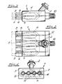
- the tool block 1 shown in the figures is intended for the extrusion of a cable guide device made of thermoplastic material with the help of an extruder. Consequently, the tool block 1 has a corresponding extruder connection 2.
- the basic structure includes a multi-part outer tool 3 and an inner tool 4.
- the tool block 1 has at least one extrusion channel 5 which determines the outer contour of a cable guide tube and therein a mandrel 6 which determines the round inner contour of the cable guide tube Crosspieces, which are components of the inner tool, are held in the outer tool 3.
- the outer contour of the cable guide tube can have any cross section. It has been hinted at in the exemplary embodiment, but not by way of limitation.
- a sliding rib tool 7 is connected to the mandrel 6, which has a profile 8 forming sliding ribs on the circumference.
- the arrangement is such that the sliding rib tool 7 is connected to a sliding rib tool shaft 9 which is mounted in the mandrel 6.
- the sliding rib tool 7 is driven via the sliding rib tool shaft 9, which is led out of the tool block 1, during the extrusion of the cable guiding device with an alternating direction of rotation and / or at different rotational speeds with the aid of an associated drive 10.
- FIGS. 2 to 7 describe tool blocks 1 which are used to produce a cable guide device with a plurality of cable guide tubes which are connected via webs and can be folded together to form a cable guide tube bundle.
- each tool block 1 has a plurality of extrusion channels 5 and mandrels 6 arranged therein with sliding rib tool 7 and sliding rib tool shaft 9.
- the extrusion channels 5 are arranged next to one another.
- the sliding rib tool shafts 9 are led out of the tool block 1 directly or via at least one intermediate shaft and connected to a drive 10.
- the extrusion channels 5 are connected to one another via web-forming slots 11.
- the webs are connecting webs between the individual cable guide tubes of the assembly consisting of several cable guide tubes.
- the sliding rib tool shafts 9 can be connected to a single drive motor via gears or each individually connected to a separate drive.
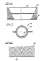
- FIG. 8 to 10 show a section of a cable routing device 14, as can be produced with the described tool blocks. It can be seen that the inner contour of the cable guide tube 15 or the cable guide tubes has sliding ribs 16 which do not run in the longitudinal direction of the cable guide tube 15 in a uniform direction, but rather have an alternating direction. For this purpose, reference is made to FIG. 10. The sliding ribs 16 could also have a direction of rotation with different pitch.
Landscapes
- Engineering & Computer Science (AREA)
- Mechanical Engineering (AREA)
- Physics & Mathematics (AREA)
- Manufacturing & Machinery (AREA)
- General Physics & Mathematics (AREA)
- Optics & Photonics (AREA)
- Extrusion Moulding Of Plastics Or The Like (AREA)
- Laying Of Electric Cables Or Lines Outside (AREA)
- Ropes Or Cables (AREA)
Abstract
Description
- Die Erfindung betrifft einen Werkzeugblock für das Strangpressen einer Kabelführungsvorrichtung aus thermoplastischem Kunststoff mit Hilfe eines Extruders, - mit einem mehrteiligen Außenwerkzeug und einem Innenwerkzeug, wobei der Werkzeugblock zumindest einen die Außenkontur eines Kabelführungsrohres bestimmenden Extrusionskanal und darin einen die runde Innenkontur des Kabelführungsrohres bestimmenden Dorn aufweist, der über Stege im Außenwerkzeug gehalten ist. Es versteht sich, daß ein solcher Werkzeugblock einen Extruderanschluß aufweist, der im Werkzeugblock im allgemeinen in eine Verteilerkammer einmündet. - Werkzeugblöcke des beschriebenen Aufbaus dienen zur Herstellung von Kabelführungseinrichtungen mit einem einzigen Kabelführungsrohr oder zur Herstellung von Aggregaten aus mehreren Kabelführungsrohren, deren einzelne Kabelführungsrohre parallel verlaufen und durch Stege verbunden sind (vgl. DE 38 06 663). Die Stege sind ausreichend flexibel, um eine Bündelung der Kabelführungsrohre zuzulassen.
- Bei den aus der Praxis bekannten Werkzeugblöcken, von denen die Erfindung ausgeht, sind die Dorne hohle oder massive Bauteile mit glattem Dornmantel. Sie sind der Innenkontur des Kabelführungsrohres bzw. der einzelnen Kabelführungsrohre angepaßt und erzeugen eine glatte Innenwand in den einzelnen Kabelführungsrohren. Der Querschnitt der Extrusionskanäle bestimmt den Außenquerschnitt der Kabelführungsrohre. Es ist bisher nicht möglich, den Innenmantel eines solchen Kabelführungsrohres bzw. der Kabelführungsrohre mit Gleitrippen alternierender Richtung oder Steigung zu versehen. Andererseits ist es bekannt, daß solche Gleitrippen das Einziehen der Kabel erleichtern.
- Der Erfindung liegt die Aufgabe zugrunde, einen Werkzeugblock des eingangs beschriebenen Aufbaus so weiter auszubilden, daß das Kabelführungsrohr bzw. die Kabelführungsrohre der Kabelführungsvorrichtung in der beschriebenen Weise mit Gleitrippen versehen werden können.
- Zur Lösung dieser Aufgabe lehrt die Erfindung, daß zum Zwecke der Erzeugung von Gleitrippen in der Innenkontur des Kabelführungsrohres mit dem Dorn ein Gleitrippenwerkzeug verbunden ist, welches umfangsseitig eine gleitrippenbildende Profilierung aufweist, daß das Gleitrippenwerkzeug an eine Gleitrippenwerkzeugwelle angeschlossen ist, die in dem Dorn gelagert ist, und daß das Gleitrippenwerkzeug über die Gleitrippenwerkzeugwelle, die aus dem Werkzeugblock herausgeführt ist, bei der Extrusion der Kabelführungsvorrichtung mit alternierendem Drehsinn und/oder mit unterschiedlichen Drehgeschwindigkeiten mit Hilfe eines zugeordneten Antriebes antreibbar ist. Im einfachsten Falle wird mit einem solchen Werkzeugblock eine Kabelführungsvorrichtung hergestellt, die ein einziges Kabelführungsrohr aufweist. Für die Herstellung einer Kabelführungsvorrichtung mit mehreren Kabelführungsrohren, die über Stege verbunden und zu einem Kabelführungsrohrbündel zusammenlegbar sind, lehrt die Erfindung, daß mehrere Extrusionskanäle und darin angeordnete Dorne mit Gleitrippenwerkzeug und Gleitrippenwerkzeugwellen nebeneinander angeordnet sind, daß die Gleitrippenwerkzeugwelle unmittelbar oder über zumindest eine Zwischenwelle aus dem Werkzeugblock herausgeführt sowie an einen Antrieb angeschlossen ist und daß die Extrusionskanäle durch stegbildende Schlitze verbunden sind.
- Im folgenden werden die beschriebenen Merkmale der Erfindung anhand einer lediglich ein Ausführungsbeispiel darstellenden Zeichnung ausführlicher erläutert. Es zeigen in schematischer Darstellung
- Fig. 1
- einen Axialschnitt durch einen erfindungsgemäßen Werkzeugblock,
- Fig. 2
- in gegenüber der Fig. 1 wesentlich verkleinertem Maßstab eine Draufsicht auf einen Werkzeugblock für die Herstellung einer Kabelführungsvorrichtung mit mehreren Kabelführungsrohren,
- Fig. 3
- eine Seitenansicht des Gegenstandes der Fig. 2,
- Fig. 4
- eine Stirnansicht des Gegenstandes der Fig. 2,
- Fig. 5
- entsprechend der Fig. 2 eine andere Ausführungsform eines Werkzeugblockes für die Herstellung einer Kabelführungsvorrichtung mit mehreren Kabelführungsrohren,
- Fig. 6
- eine Seitenansicht des Gegenstandes der Fig. 5,
- Fig. 7
- eine Stirnansicht des Gegenstandes der Fig. 5,
- Fig. 8
- ein Kabelführungsrohr, welches mit Hilfe eines erfindungsgemäßen Werkzeugblockes hergestellt wurde, in der Seitenansicht, teilweise aufgebrochen,
- Fig. 9
- einen Querschnitt durch den Gegenstand der Fig. 8, und
- Fig. 10
- in der Abwicklung Gleitrippen einer hergestellten Kabelführungsvorrichtung.
- Der in den Figuren dargestellte Werkzeugblock 1 ist für das Strangpressen einer Kabelführungsvorrichtung aus thermoplastischem Kunststoff mit Hilfe eines Extruders bestimmt. Folglich besitzt der Werkzeugblock 1 einen entsprechenden Extruderanschluß 2. Zum grundsätzlichen Aufbau gehören ein mehrteiliges Außenwerkzeug 3 und ein Innenwerkzeug 4. Der Werkzeugblock 1 besitzt zumindest einen die Außenkontur eines Kabelführungsrohres bestimmenden Extrusionskanal 5 und darin einen die runde Innenkontur des Kabelführungsrohres bestimmenden Dorn 6, der über Stege, die Bauteile des Innenwerkzeuges sind, im Außenwerkzeug 3 gehalten ist. Die Außenkontur des Kabelführungsrohres kann einen beliebigen Querschnitt aufweisen. Sie ist im Ausführungsbeispiel, jedoch nicht beschränkend, rund angedeutet worden.
- Zum Zwecke der Erzeugung von Gleitrippen in der Innenkontur des Kabelführungsrohres (vgl. die Fig. 8 bis 10), ist mit dem Dorn 6 jeweils ein Gleitrippenwerkzeug 7 verbunden, welches umfangsseitig eine gleitrippenbildende Profilierung 8 aufweist. Die Anordnung ist so getroffen, daß das Gleitrippenwerkzeug 7 an eine Gleitrippenwerkzeugwelle 9 angeschlossen ist, die in dem Dorn 6 gelagert ist. Das Gleitrippenwerkzeug 7 ist über die Gleitrippenwerkzeugwelle 9, die aus dem Werkzeugblock 1 herausgeführt ist, bei der Extrusion der Kabelführungsvorrichtung mit alternierendem Drehsinn und/oder mit unterschiedlicher Drehgeschwindigkeit mit Hilfe eines zugeordneten Antriebes 10 angetrieben.
- Die Fig. 1 zeigt die Ausführungsform eines erfindungsgemäßen Werkzeugblockes 1 zur Herstellung einer Kabelführungsvorrichtung, die ein einziges Kabelführungsrohr aufweist. In den Fig. 2 bis 7 sind demgegenüber Werkzeugblöcke 1 beschrieben, die für die Herstellung einer Kabelführungsvorrichtung mit mehreren Kabelführungsrohren, die über Stege verbunden und zu einem Kabelführungsrohrbündel zusammenlegbar sind, dargestellt. Jeder Werkzeugblock 1 besitzt in den Fig. 2 bis 7 mehrere Extrusionskanäle 5 und darin angeordnete Dorne 6 mit Gleitrippenwerkzeug 7 und Gleitrippenwerkzeugwelle 9. Die Extrusionskanäle 5 sind nebeneinander angeordnet. Die Gleitrippenwerkzeugwellen 9 sind unmittelbar oder über zumindest eine Zwischenwelle aus dem Werkzeugblock 1 herausgeführt sowie an einen Antrieb 10 angeschlossen. Die Extrusionskanäle 5 sind über stegbildende Schlitze 11 miteinander verbunden. Die Stege sind Verbindungsstege zwischen den einzelnen Kabelführungsrohren des aus mehreren Kabelführungsrohren bestehenden Aggregates.
- Die Fig. 2 bis 4 zeigen die Ausführungsform, bei der der Extruderanschluß 2 an der Oberseite des Werkzeugblockes 1 angeordnet ist und die Gleitrippenwerkzeugwellen 9 an der den Extrusionskanälen 5 gegenüberliegenden Seite aus dem Werkzeugblock 1 herausgeführt sind. Die Fig. 5 bis 7 zeigen die Ausführungsform, bei der der Extruderanschluß 2 an der den Extrusionskanälen 5 gegenüberliegenden Seite an den Werkzeugblock 1 angeschlossen ist und die Gleitrippenwerkzeugwellen 9 über ein Kegelradgetriebe 12 an eine Zwischenwelle 13 angeschlossen sind, die an der Oberseite und/oder Unterseite aus dem Werkzeugblock 1 herausgeführt sind. Außerdem wurde in Fig. 5 angedeutet, daß die Gleitrippenwerkzeugwellen 9 über ein Kegelradgetriebe 12 an eine Zwischenwelle 13 angeschlossen sind, die eine der Anzahl der Gleitrippenwerkzeugwellen 9 entsprechende Anzahl von Kegelrädern trägt und seitlich aus dem Werkzeugblock 1 herausgeführt ist. Die Gleitrippenwerkzeugwellen 9 können über Getriebe an einen einzigen Antriebsmotor angeschlossen sein oder jede einzeln mit einem separaten Antrieb verbunden sein.
- In den Fig. 8 bis 10 erkennt man einen Ausschnitt aus einer Kabelführungsvorrichtung 14, wie sie mit den beschriebenen Werkzeugblöcken herstellbar ist. Man erkennt, daß die Innenkontur des Kabelführungsrohres 15 bzw. der Kabelführungsrohre Gleitrippen 16 aufweist, die nicht mit einheitlicher Richtung in Längsrichtung des Kabelführungsrohres 15 verlaufen, sondern vielmehr eine alternierende Richtung aufweisen. Dazu wird auf die Fig. 10 verwiesen. Die Gleitrippen 16 könnten auch einen Drehsinn mit unterschiedlicher Steigung aufweisen.
Claims (5)
- Werkzeugblock für das Strangpressen einer Kabelführungsvorrichtung aus thermoplastischem Kunststoff mit Hilfe eines Extruders, - mit
einem mehrteiligen Außenwerkzeug und einem Innenwerkzeug,
wobei der Werkzeugblock zumindest einen die Außenkontur eines Kabelführungsrohres bestimmenden Extrusionskanal und darin einen die runde Innenkontur des Kabelführungsrohres bestimmenden Dorn aufweist, der über Stege im Außenwerkzeug gehalten ist, dadurch gekennzeichnet, daß zum Zwecke der Erzeugung von Gleitrippen (16) in der Innenkontur des Kabelführungsrohres (15) mit dem Dorn (6) ein Gleitrippenwerkzeug (7) verbunden ist, welches umfangsseitig eine gleitrippenbildende Profilierung (8) aufweist, daß das Gleitrippenwerkzeug (7) an eine Gleitrippenwerkzeugwelle (9) angeschlossen ist, die in dem Dorn (6) gelagert ist, und daß das Gleitrippenwerkzeug (7) über die Gleitrippenwerkzeugwelle (9), die aus dem Werkzeugblock (1) herausgeführt ist, bei der Extrusion der Kabelführungsvorrichtung mit alternierendem Drehsinn und/oder mit unterschiedlichen Drehgeschwindigkeiten mit Hilfe eines zugeordneten Antriebes (10) antreibbar ist. - Werkzeugblock nach Anspruch 1, dadurch gekennzeichnet, daß für die Herstellung einer Kabelführungsvorrichtung mit mehreren Kabelführungsrohren (15), die über Stege verbunden und zu einem Kabelführungsrohrbündel zusammenlegbar sind, mehrere über stegbildende Schlitze (11) verbundene Extrusionskanäle (5) und darin angeordnete Dorne (6) mit Gleitrippenwerkzeug (7) und Gleitrippenwerkzeugwelle (9) nebeneinander angeordnet sind und daß die Gleitrippenwerkzeugwellen (9) unmittelbar oder über zumindest eine Zwischenwelle (13) aus dem Werkzeugblock (1) herausgeführt sowie an einen Antrieb (10) angeschlossen sind.
- Werkzeugblock nach Anspruch 2, dadurch gekennzeichnet, daß der Extruderanschluß (2) an der Oberseite des Werkzeugblockes (1) angeordnet und die Gleitrippenwerkzeugwellen (9) an der den Extrusionskanälen (5) gegenüberliegenden Seite aus dem Werkzeugblock (1) herausgeführt sind.
- Werkzeugblock nach Anspruch 2, dadurch gekennzeichnet, daß der Extruderanschluß (2) an der den Extrusionskanälen (5) gegenüberliegenden Seite an den Werkzeugblock (1) angeschlossen ist und die Gleitrippenwerkzeugwellen (9) über ein Kegelradgetriebe (12) an eine Zwischenwelle (13) angeschlossen sind, die an der Oberseite und/oder an der Unterseite aus dem Werkzeugblock (1) herausgeführt sind.
- Werkzeugblock nach Anspruch 2, dadurch gekennzeichnet, daß der Extruderanschluß (2) an der den Extrusionskanälen (5) gegenüberliegenden Seite an den Werkzeugblock (1) angeschlossen ist und die Gleitrippenwerkzeugwellen (9) über ein Kegelradgetriebe (12) an eine Zwischenwelle (13) angeschlossen sind, die eine der Anzahl der Gleitrippenwerkzeugwellen (9) entsprechende Anzahl von Kegelrädern trägt und seitlich aus dem Werkzeugblock (1) herausgeführt ist.
Applications Claiming Priority (4)
| Application Number | Priority Date | Filing Date | Title |
|---|---|---|---|
| DE4016726 | 1990-05-24 | ||
| DE4016726A DE4016726C1 (de) | 1990-05-24 | 1990-05-24 | |
| DE4030674A DE4030674A1 (de) | 1990-09-28 | 1990-09-28 | Werkzeugblock fuer das strangpressen eines aggregates aus mehreren kabelfuehrungsrohren |
| DE4030674 | 1990-09-28 |
Publications (3)
| Publication Number | Publication Date |
|---|---|
| EP0458139A2 true EP0458139A2 (de) | 1991-11-27 |
| EP0458139A3 EP0458139A3 (en) | 1992-04-08 |
| EP0458139B1 EP0458139B1 (de) | 1995-07-26 |
Family
ID=25893507
Family Applications (1)
| Application Number | Title | Priority Date | Filing Date |
|---|---|---|---|
| EP91107565A Expired - Lifetime EP0458139B1 (de) | 1990-05-24 | 1991-05-09 | Werkzeugblock für das Strangpressen einer Kabelführungsvorrichtung |
Country Status (10)
| Country | Link |
|---|---|
| EP (1) | EP0458139B1 (de) |
| JP (1) | JPH06133436A (de) |
| KR (1) | KR910019749A (de) |
| AT (1) | ATE125484T1 (de) |
| CS (1) | CS151291A3 (de) |
| DE (1) | DE59106070D1 (de) |
| DK (1) | DK0458139T3 (de) |
| ES (1) | ES2074605T3 (de) |
| GR (1) | GR3017083T3 (de) |
| PL (1) | PL165975B1 (de) |
Cited By (4)
| Publication number | Priority date | Publication date | Assignee | Title |
|---|---|---|---|---|
| EP0744268A1 (de) * | 1995-05-24 | 1996-11-27 | KE-KELIT Kunststoffwerk Gesellschaft m.b.H. | Ringdüse zum Strangpressen von Kunststoffschläuchen zur Rohrisolierung gegen Wärme- und Schallübertragung |
| ES2115425A1 (es) * | 1992-10-12 | 1998-06-16 | Solvay | Conducto protector para cables constituido por tubo ranurado de materia termoplastica, y dispositivo para su fabricacion. |
| EP1001503A1 (de) * | 1998-11-09 | 2000-05-17 | Uponor Innovation Ab | Kabelkanal und verfahren und vorrichtung zur herstellung eines kabelkanals |
| CN111516238A (zh) * | 2020-05-06 | 2020-08-11 | 深圳市特发信息光网科技股份有限公司 | 一种热流道线缆挤出头 |
Families Citing this family (1)
| Publication number | Priority date | Publication date | Assignee | Title |
|---|---|---|---|---|
| CN102806650A (zh) * | 2012-09-17 | 2012-12-05 | 江苏通鼎光电科技有限公司 | 一种生产电缆单线挤塑模具 |
Citations (6)
| Publication number | Priority date | Publication date | Assignee | Title |
|---|---|---|---|---|
| US3496605A (en) * | 1965-10-26 | 1970-02-24 | Yasuyoshi Onaka | Apparatus for extruding ribbed plastic pipe |
| DE1808271A1 (de) * | 1968-09-10 | 1970-04-02 | Yukio Nishikawa | Kunstharzfolien oder Schlaeuche |
| US3666389A (en) * | 1969-11-24 | 1972-05-30 | Dominion Gasket & Mfg Co Ltd | Extrusion apparatus for making conduit pipe |
| GB2096533A (en) * | 1981-04-14 | 1982-10-20 | Nat Res Dev | Improvements in or relating to extrusion |
| GB2135136A (en) * | 1983-02-09 | 1984-08-22 | Wavin Bv | Insert for a cable-duct tube |
| FR2580437A1 (fr) * | 1985-04-12 | 1986-10-17 | Sterling Ste Electr | Procede de fabrication d'un element tubulaire monobloc pour la protection de plusieurs cables et element fabrique selon ce procede |
-
1991
- 1991-05-09 AT AT91107565T patent/ATE125484T1/de not_active IP Right Cessation
- 1991-05-09 DK DK91107565.3T patent/DK0458139T3/da active
- 1991-05-09 EP EP91107565A patent/EP0458139B1/de not_active Expired - Lifetime
- 1991-05-09 ES ES91107565T patent/ES2074605T3/es not_active Expired - Lifetime
- 1991-05-09 DE DE59106070T patent/DE59106070D1/de not_active Expired - Fee Related
- 1991-05-20 PL PL91290325A patent/PL165975B1/pl unknown
- 1991-05-22 CS CS911512A patent/CS151291A3/cs unknown
- 1991-05-23 KR KR1019910008312A patent/KR910019749A/ko active IP Right Grant
- 1991-05-23 JP JP3118506A patent/JPH06133436A/ja active Pending
-
1995
- 1995-08-09 GR GR950402213T patent/GR3017083T3/el unknown
Patent Citations (6)
| Publication number | Priority date | Publication date | Assignee | Title |
|---|---|---|---|---|
| US3496605A (en) * | 1965-10-26 | 1970-02-24 | Yasuyoshi Onaka | Apparatus for extruding ribbed plastic pipe |
| DE1808271A1 (de) * | 1968-09-10 | 1970-04-02 | Yukio Nishikawa | Kunstharzfolien oder Schlaeuche |
| US3666389A (en) * | 1969-11-24 | 1972-05-30 | Dominion Gasket & Mfg Co Ltd | Extrusion apparatus for making conduit pipe |
| GB2096533A (en) * | 1981-04-14 | 1982-10-20 | Nat Res Dev | Improvements in or relating to extrusion |
| GB2135136A (en) * | 1983-02-09 | 1984-08-22 | Wavin Bv | Insert for a cable-duct tube |
| FR2580437A1 (fr) * | 1985-04-12 | 1986-10-17 | Sterling Ste Electr | Procede de fabrication d'un element tubulaire monobloc pour la protection de plusieurs cables et element fabrique selon ce procede |
Non-Patent Citations (1)
| Title |
|---|
| PATENT ABSTRACTS OF JAPAN vol. 14, no. 266 (M-982)(4209) 8. Juni 1990 & JP-A-2 078 517 ( SUMITOMO ) 19. März 1990 * |
Cited By (4)
| Publication number | Priority date | Publication date | Assignee | Title |
|---|---|---|---|---|
| ES2115425A1 (es) * | 1992-10-12 | 1998-06-16 | Solvay | Conducto protector para cables constituido por tubo ranurado de materia termoplastica, y dispositivo para su fabricacion. |
| EP0744268A1 (de) * | 1995-05-24 | 1996-11-27 | KE-KELIT Kunststoffwerk Gesellschaft m.b.H. | Ringdüse zum Strangpressen von Kunststoffschläuchen zur Rohrisolierung gegen Wärme- und Schallübertragung |
| EP1001503A1 (de) * | 1998-11-09 | 2000-05-17 | Uponor Innovation Ab | Kabelkanal und verfahren und vorrichtung zur herstellung eines kabelkanals |
| CN111516238A (zh) * | 2020-05-06 | 2020-08-11 | 深圳市特发信息光网科技股份有限公司 | 一种热流道线缆挤出头 |
Also Published As
| Publication number | Publication date |
|---|---|
| CS151291A3 (en) | 1992-02-19 |
| DE59106070D1 (de) | 1995-08-31 |
| KR910019749A (ko) | 1991-12-19 |
| PL165975B1 (pl) | 1995-03-31 |
| ES2074605T3 (es) | 1995-09-16 |
| PL290325A1 (en) | 1992-01-27 |
| JPH06133436A (ja) | 1994-05-13 |
| GR3017083T3 (en) | 1995-11-30 |
| ATE125484T1 (de) | 1995-08-15 |
| DK0458139T3 (da) | 1995-09-11 |
| EP0458139B1 (de) | 1995-07-26 |
| EP0458139A3 (en) | 1992-04-08 |
Similar Documents
| Publication | Publication Date | Title |
|---|---|---|
| DE3633021C2 (de) | ||
| DE3521485C2 (de) | Vorrichtung zur Herstellung eines verseilten, mehrdrähtigen, verdichteten Rundleiters | |
| DE2923132C2 (de) | Verfahren zur Herstellung eines Kunststoffadens für ein optisches Kabel sowie Vorrichtung zur Durchführung dieses Verfahrens | |
| DE3108691A1 (de) | Schneide- und/oder rillmaschine fuer papier-, pappen- oder schichtpressstoffrollen | |
| DE1938214A1 (de) | Vorrichtung zur Herstellung eines Bandes aus nicht vulkanisiertem bzw. nicht polymerisiertem elastomerem Material,in das eine Mehrzahl Verstaerkungsdraehte eingebettet ist | |
| DE3217401A1 (de) | Kabelfuehrungsaggregat | |
| DE4016726C1 (de) | ||
| AT380717B (de) | Mast aus holz, insbesondere zur freileitung od.dgl. und maschine zur herstellung desselben | |
| DE8907321U1 (de) | Rohr, insbesondere Umlenkwelle, Expansionswelle o.dgl. | |
| DE2262705B2 (de) | Einrichtung zur kontinuierlichen herstellung eines elektrokabels | |
| EP0458139B1 (de) | Werkzeugblock für das Strangpressen einer Kabelführungsvorrichtung | |
| DE3109756C2 (de) | Vertikale Verseilmaschine | |
| DE4306813A1 (de) | Verfahren zur Herstellung eines aus Kunststoff bestehenden Kabelführungskanals | |
| DE60121712T2 (de) | Gerät zum Verdrehen von Glasfaserbandkabeln und Herstellungssystem für optische Kabelkomponenten | |
| WO1988005969A1 (en) | Tool for laying and cutting cables into lengths by means of a handling device | |
| DE2106889A1 (de) | Vorrichtung und Verfahren zur gleich zeitigen Herstellung mehrerer Kraftuber tragungsnemen | |
| DE69123491T2 (de) | Verbesserungen an Vorseilmaschinen | |
| EP3672741B1 (de) | Antriebssystem und profiliermodul für eine profilieranlage | |
| DE2060261B2 (de) | Verfahren zum Herstellen eines Rohres aus faserverstärktem Kunststoff sowie Verfahren zur Durch führung des Verfahrens | |
| DE4031783A1 (de) | Kabelfuehrungseinrichtung mit zumindest einem kabelfuehrungsrohr aus thermoplastischem kunststoff | |
| DE1222656B (de) | Strangpressverfahren und Mehrfarbenstrangpresse zum Aufbringen einer Umhuellung auf einen strangfoermigen Koerper | |
| DE1629188B2 (de) | Vorrichtung zum Herstellen von verstärkten Harzgegenständen | |
| DE2632148A1 (de) | Kabelabzugsvorrichtung | |
| DE4030674A1 (de) | Werkzeugblock fuer das strangpressen eines aggregates aus mehreren kabelfuehrungsrohren | |
| DE3503254A1 (de) | Zweistufige verseileinrichtung fuer nachrichtenkabel |
Legal Events
| Date | Code | Title | Description |
|---|---|---|---|
| PUAI | Public reference made under article 153(3) epc to a published international application that has entered the european phase |
Free format text: ORIGINAL CODE: 0009012 |
|
| AK | Designated contracting states |
Kind code of ref document: A2 Designated state(s): AT BE CH DE DK ES FR GB GR IT LI LU NL SE |
|
| 17P | Request for examination filed |
Effective date: 19911109 |
|
| PUAL | Search report despatched |
Free format text: ORIGINAL CODE: 0009013 |
|
| AK | Designated contracting states |
Kind code of ref document: A3 Designated state(s): AT BE CH DE DK ES FR GB GR IT LI LU NL SE |
|
| 17Q | First examination report despatched |
Effective date: 19930929 |
|
| GRAA | (expected) grant |
Free format text: ORIGINAL CODE: 0009210 |
|
| AK | Designated contracting states |
Kind code of ref document: B1 Designated state(s): AT BE CH DE DK ES FR GB GR IT LI LU NL SE |
|
| REF | Corresponds to: |
Ref document number: 125484 Country of ref document: AT Date of ref document: 19950815 Kind code of ref document: T |
|
| ITF | It: translation for a ep patent filed | ||
| REF | Corresponds to: |
Ref document number: 59106070 Country of ref document: DE Date of ref document: 19950831 |
|
| ET | Fr: translation filed | ||
| REG | Reference to a national code |
Ref country code: DK Ref legal event code: T3 |
|
| REG | Reference to a national code |
Ref country code: ES Ref legal event code: FG2A Ref document number: 2074605 Country of ref document: ES Kind code of ref document: T3 |
|
| GBT | Gb: translation of ep patent filed (gb section 77(6)(a)/1977) |
Effective date: 19950914 |
|
| REG | Reference to a national code |
Ref country code: GR Ref legal event code: FG4A Free format text: 3017083 |
|
| PGFP | Annual fee paid to national office [announced via postgrant information from national office to epo] |
Ref country code: LU Payment date: 19960401 Year of fee payment: 6 |
|
| PGFP | Annual fee paid to national office [announced via postgrant information from national office to epo] |
Ref country code: GB Payment date: 19960423 Year of fee payment: 6 |
|
| PGFP | Annual fee paid to national office [announced via postgrant information from national office to epo] |
Ref country code: SE Payment date: 19960425 Year of fee payment: 6 |
|
| PGFP | Annual fee paid to national office [announced via postgrant information from national office to epo] |
Ref country code: GR Payment date: 19960510 Year of fee payment: 6 |
|
| PGFP | Annual fee paid to national office [announced via postgrant information from national office to epo] |
Ref country code: BE Payment date: 19960513 Year of fee payment: 6 |
|
| PGFP | Annual fee paid to national office [announced via postgrant information from national office to epo] |
Ref country code: FR Payment date: 19960515 Year of fee payment: 6 |
|
| PGFP | Annual fee paid to national office [announced via postgrant information from national office to epo] |
Ref country code: DK Payment date: 19960517 Year of fee payment: 6 |
|
| PGFP | Annual fee paid to national office [announced via postgrant information from national office to epo] |
Ref country code: ES Payment date: 19960520 Year of fee payment: 6 |
|
| PGFP | Annual fee paid to national office [announced via postgrant information from national office to epo] |
Ref country code: CH Payment date: 19960524 Year of fee payment: 6 |
|
| PGFP | Annual fee paid to national office [announced via postgrant information from national office to epo] |
Ref country code: NL Payment date: 19960531 Year of fee payment: 6 Ref country code: AT Payment date: 19960531 Year of fee payment: 6 |
|
| PLBE | No opposition filed within time limit |
Free format text: ORIGINAL CODE: 0009261 |
|
| STAA | Information on the status of an ep patent application or granted ep patent |
Free format text: STATUS: NO OPPOSITION FILED WITHIN TIME LIMIT |
|
| 26N | No opposition filed | ||
| PG25 | Lapsed in a contracting state [announced via postgrant information from national office to epo] |
Ref country code: LU Free format text: LAPSE BECAUSE OF NON-PAYMENT OF DUE FEES Effective date: 19970509 Ref country code: GB Effective date: 19970509 Ref country code: DK Free format text: LAPSE BECAUSE OF NON-PAYMENT OF DUE FEES Effective date: 19970509 Ref country code: AT Effective date: 19970509 |
|
| REG | Reference to a national code |
Ref country code: DK Ref legal event code: EBP |
|
| PG25 | Lapsed in a contracting state [announced via postgrant information from national office to epo] |
Ref country code: SE Effective date: 19970510 Ref country code: ES Free format text: LAPSE BECAUSE OF NON-PAYMENT OF DUE FEES Effective date: 19970510 |
|
| PG25 | Lapsed in a contracting state [announced via postgrant information from national office to epo] |
Ref country code: LI Free format text: LAPSE BECAUSE OF NON-PAYMENT OF DUE FEES Effective date: 19970531 Ref country code: CH Free format text: LAPSE BECAUSE OF NON-PAYMENT OF DUE FEES Effective date: 19970531 Ref country code: BE Effective date: 19970531 |
|
| BERE | Be: lapsed |
Owner name: ERNST VOGELSANG G.M.B.H. & CO. K.G. Effective date: 19970531 |
|
| PG25 | Lapsed in a contracting state [announced via postgrant information from national office to epo] |
Ref country code: GR Free format text: THE PATENT HAS BEEN ANNULLED BY A DECISION OF A NATIONAL AUTHORITY Effective date: 19971130 |
|
| PG25 | Lapsed in a contracting state [announced via postgrant information from national office to epo] |
Ref country code: NL Effective date: 19971201 |
|
| REG | Reference to a national code |
Ref country code: GR Ref legal event code: MM2A Free format text: 3017083 |
|
| GBPC | Gb: european patent ceased through non-payment of renewal fee |
Effective date: 19970509 |
|
| REG | Reference to a national code |
Ref country code: CH Ref legal event code: PL |
|
| PG25 | Lapsed in a contracting state [announced via postgrant information from national office to epo] |
Ref country code: FR Free format text: LAPSE BECAUSE OF NON-PAYMENT OF DUE FEES Effective date: 19980130 |
|
| EUG | Se: european patent has lapsed |
Ref document number: 91107565.3 |
|
| NLV4 | Nl: lapsed or anulled due to non-payment of the annual fee |
Effective date: 19971201 |
|
| REG | Reference to a national code |
Ref country code: FR Ref legal event code: ST |
|
| PGFP | Annual fee paid to national office [announced via postgrant information from national office to epo] |
Ref country code: DE Payment date: 20030410 Year of fee payment: 13 |
|
| REG | Reference to a national code |
Ref country code: ES Ref legal event code: FD2A Effective date: 19980611 |
|
| PG25 | Lapsed in a contracting state [announced via postgrant information from national office to epo] |
Ref country code: DE Free format text: LAPSE BECAUSE OF NON-PAYMENT OF DUE FEES Effective date: 20041201 |
|
| PG25 | Lapsed in a contracting state [announced via postgrant information from national office to epo] |
Ref country code: IT Free format text: LAPSE BECAUSE OF NON-PAYMENT OF DUE FEES Effective date: 20050509 |